Development of an Experimental Platform
for Architectural-Scale Robotics:
The Digital Construction Platform
byJulian Leland Bell
B.S., Engineering and Public Policy, Swarthmore College, 2012 Submitted to the
Department of Mechanical Engineering
in Partial Fulfilment of the Requirements for the Degree of Master of Science in Mechanical Engineering
at the
Massachusetts Institute of Technology September 2017
2017 Massachusetts Institute of Technology. All rights reserved
Signature of Author: ... Department of Mechanical Engineering August 11th, 2017
Certified by: ... Neri Oxman Associate Professor of Media Arts and Sciences Thesis Co-Supervisor Certified by: ... David L. Trumper Professor of Mechanical Engineering Thesis Co-Supervisor
Development of an Experimental Platform for Architectural-Scale
Robotics: The Digital Construction Platform
by
Julian Leland Bell
Submitted to the Department of Mechanical Engineering
on August 18, 2017 in partial fulfilment of the requirements for the degree of Master of Science in Mechanical Engineering
Abstract
This thesis describes the development and refinement of the second prototype of the Digital Construction Platform, or DCP. The DCP is a serial-link micro-macro manipulator robot intended for architectural-scale fabrication tasks, originally conceived of and presented by Keating in [1]. It is envisioned primarily as a platform for experimentation in automated construction, rather than as a closed, single-application system.
In the work described here, a second prototype of the DCP – referred to as the DCP v.2 – was developed over two distinct periods. During the first period, from September 2015 through August 2016, the DCP v.2 system was assembled and a basic command and control architecture was developed to operate it. A series of experiments were conducted to examine the system’s performance, including pose repeatability testing in accordance with the ISO 9283-1998 robot performance characterization standard; and the fabrication of an architectural-scale dome structure from spray polyurethane foam.
During the second period, from September 2016 through August 2016, the DCP v.2 system and command/control architecture were modified in a variety of ways to improve performance, reliability, accessibility to new users, and adaptability to new tasks. These modifications included transition to a modular, hard-real-time control architecture; installation of additional sensor systems on the vehicle; and the refinement and standardization of the system’s toolpath generation architecture. The impact of this work was demonstrated through a second set of demonstrations, including large-scale light paintings leveraging the new control architecture’s capabilities; and re-characterization of the system’s ISO 9283 pose repeatability, demonstrating a 59% improvement in this metric.
Acknowledgements
My path through this project begins with the DCP team. Steve Keating is the original inventor of the DCP and Print-in-Place concepts – basically, all the really good ideas here – and led the DCP project through August 2016. It is thanks to him that I have had the opportunity to be a part of this incredible project, and to help turn these visions into reality: I am deeply grateful. Along the way, many other people have lent their talents to the project, including Levi Cai, Selam Gano, John Zhang, Barrak Darweesh, Owen Trueblood, Damien Martin, and Grant Sellers. Thank you all for your help, patience, guidance and good humour.
Second, I would like to acknowledge my advisors: Dr. Neri Oxman and Dr. David Trumper. In coming to MIT, I wanted to grow as an engineer, but also to reach beyond my discipline in my work. The two of you have made this possible, enabling me to pursue a mechanical engineering degree while working on the DCP project, and providing equal parts technical rigor and
multidisciplinary grace in your mentorship. It has been an honor to learn from each of you. The Mediated Matter Group has also played an instrumental role in helping me develop beyond being “just an engineer.” I doubt I will ever again have the opportunity to surround myself with such intellectual diversity, and I cannot thank you all enough for inviting me to be a part of this rare team.
MIT is much more than just students and professors. I would particularly like to thank the many shop masters I have bothered over the past two years, including John DiFrancesco and Tom Lutz at the Media Lab shop; Tara Fadenrecht at the DMSE shop; Mark Belanger at Edgerton; and Jen O’Brien at the Architecture shop. Additionally, as with any large institution there are a small set of people at MIT who do a huge amount to keep the entire operation running smoothly: Leslie Reagan in Mechanical Engineering, Keira Horowitz at the Media Lab, and the indomitable Kelly Donovan at Mediated Matter. Thank you all for your patience, help and kindness.
A range of companies and organizations have helped make my work with the DCP possible through their support, including the following:
- Altec, Inc.: I am particularly grateful to David Boger, whose persistent belief in our vision for the DCP has made realizing that vision possible. I would also like to thank the many Altec employees who have generously given their time to support our work,
including Ali Khodadadi, Jessica Patel, Dan Nelson, Mike Whittaker, Jesse Thompson, and Tim Mourlam.
- Dow Chemical: Dow Chemical generously donated the FROTH-PAK™ spray foam insulation used in the dome print. I would like to particularly thank EJ Herst, Sven Claessens, and Ed Greer for their support in making this happen.
- Autodesk: Finally, for the past year, the DCP has been housed at the Autodesk BUILD Space. I would like to thank Rick Rundell, BUILD Space mastermind, for giving me the opportunity to work in this amazing environment. I would also like to thank the
incomparable BUILD Space shop team for their support and kindness, including Adam Allard, Athena Moore, Taylor Tobin, Tim Brinkerhoff, Joe Aronis, and Josh Aigen. I have been lucky to have a team of wise engineers as mentors and advisors who have helped me get to – and through – MIT, including Dr. Faruq Siddiqui, Dr. Lynne Molter, Dr. Erik Cheever, Dr. Bill Townsend, Dave Wilkinson, and Scott Harris. Your counsel and support is invaluable, and I look to your example as I begin to mentor the next generation of engineers.
From an early age, I was taught that education is beyond value. Thanks to the hard work and sacrifice of my parents and grandparents, I have had the privilege to learn at some of the finest institutions in the world, for which I cannot overstate my gratitude. I am particularly grateful to my parents, Annette and Jonathan Leland, who have always given me their unwavering support throughout my educational journey.
Finally, to my wife, Avery Davis Bell. The life we continue to build together is my finest project, and I could not ask for a better partner to build it with.
Author’s Note
This thesis has turned out to be quite long, which I think is unfortunately more of a reflection of my limitations as a writer than the magnitude of my contributions. However, this length allows for a corresponding degree of detail to describe the work I have done on the Digital Construction Platform (DCP). Particularly for a project where my primary objective has been to provide a tool that others can use, my hope is that this detail will prove useful for future users and developers of the DCP system.
In light of this, there are two ways this thesis may be read:
- For the reader who is interested in learning about the DCP and its contributions to the field of automated construction, I recommend reading Chapter 1, followed by the System Implementations sections in Chapters 2 and 3. This provides a brief review of the history of automated construction as well as the early development of the DCP concept;
followed by detailed descriptions of the tasks the DCP v.2 system has been used for. The reader may also wish to refer to [2] and [3] for further information about the project and its history.
- Future users of the DCP v.2 platform are advised to skip directly to Chapter 3, and use it as a guide to explore the dcpctrl_v2 repository, which hosts the DCP’s software architecture. Other sections of this thesis may be useful as reference sources, but this chapter contains the material most relevant to the DCP as it exists in August 2017.
I hope that this is helpful.
This thesis was formatted using the LaTeX 7 template by Sebastian Nilsson [4].
Dedicated to the memory of my grandfather, Benjamin Towne Leland,
engineer, aviator and eternally curious mechanical mind, who would have thought this project was pretty nifty.
Table of Contents
List of Figures ... 10
List of Tables ... 15
1
Introduction ... 17
1.1 Background ... 17
1.1.1 Historical Efforts in Automated Construction ... 17
1.1.2 Contemporary Automated Construction ... 19
1.1.3 Comparative Performance Analysis ... 28
1.2 Prior W ork ... 33
1.2.1 The Micro-Macro Manipulator ... 33
1.2.2 The DCP v.1 ... 35
1.2.3 Print-in-Place Fabrication ... 37
2
D CP v.2 System D evelopm ent ... 45
2.1 System Developm ent ... 46
2.1.1 DCP v.2 Hardware ... 46
2.1.2 DCP v.2 Control & Software Architecture... 67
2.2 System Im plementations, 2015-2016 ... 76
2.2.1 Implementation 1: Light Paintings ... 77
2.2.2 Implementation 2: ISO 9283 Characterization ... 89
2.2.3 Implementation 3: Print-in-Place Fabrication ... 94
2.3 R eview of D CP v.2 A rchitecture 2015-2016... 111
2.3.1 The DCP v.2. in Context ... 112
2.3.2 DCP v.2 Architecture Weaknesses ... 115
3
D CP v.2 System R efinem ent ... 119
3.1 G uiding Functional R equirements... 119
3.2 System Im provements ... 121
3.2.1 Simulink Desktop Real-Time Control Architecture ... 122
3.2.3 Sensing & Control Improvements ... 148
3.2.4 Toolpath Generation Architecture Improvements ... 186
3.3 System Im plementations, 2016-2017 ... 196
3.3.1 Advanced Light Paintings ... 196
3.3.2 DCP Multi-Modal Control & Toolpath Segmentation ... 201
3.3.3 ISO 9283 Performance Characterization ... 209
3.3.4 System Operation Manual ... 214
3.4 Conclusions & Future W ork ... 215
3.4.1 Lessons Learned 1: DCP v.2 Platform Improvement... 217
3.4.2 Lessons Learned 2: Arm-Based Automated Construction Systems ... 220
3.4.3 Lessons Learned 3: The Future of Automated Construction ... 222
List of Figures
Figure 1: Contour Crafting Wall [20] ... 20
Figure 2: D-Shape Radiolara Sculpture ... 21
Figure 3: Alcobendas Footbridge ... 21
Figure 4: The Sequential Roof ... 22
Figure 5: Gantenbein Vineyard Façade ... 23
Figure 6: ACS Comparison Axes ... 26
Figure 7: ACS Comparison Mapping by Kinematic Type ... 30
Figure 8: ACS Comparison Mapping by Fabrication Modality ... 31
Figure 9: Print-in-Place formwork sample for ISO 4287 roughness characterization ... 40
Figure 10: Roughness contours, ISO 4287 characterization ... 41
Figure 11: Early experiments with Print-in-Place fabrication. Clockwise from top left: 1) Wall, finished with conventional ICF finishing techniques. 2) Tilted columns fabricated with PiP process. 3) PiP foam can be machined to improve surface finish and geometric accuracy. 4) Example of double curvatures achievable with PiP. Photography credit (all images): Steven Keating. Images a and c originally published in [50]. ... 43
Figure 12: DCP approximate system dimensions, meters and [feet inches]. ... 47
Figure 13: AT40GW controlled joint definitions ... 48
Figure 14: AT40GW DH parameters ... 50
Figure 15: AT40GW natural frequency characterization – sensor orientation. ... 52
Figure 16: Summary test data from AT40GW natural frequency characterization ... 54
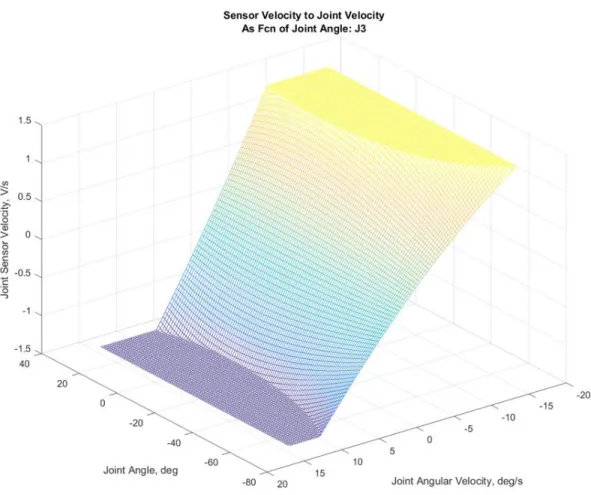
Figure 17: J3 joint sensor configuration (measurement along red line) ... 58
Figure 18: J3 sensor velocity to joint velocity mapping as function of joint position ... 59
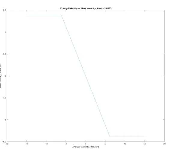
Figure 19: J3 angular velocity to sensor velocity mapping ... 60
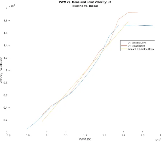
Figure 20: Generic PWM-joint velocity mapping. PWM duty cycle defined for LabJack T7, with 0-160,000 range corresponding to 0-100% duty cycle. Image created in collaboration with Selam Gano. ... 61
Figure 21: J1 sensor velocity-PWM relationship: diesel vs. electric pump. ... 63
Figure 22: J1 sensor velocity-PWM mapping ... 64
Figure 24: J4 sensor velocity-PWM relationship, multiple J3 poses ... 66 Figure 25: DCP trajectory generation workflow. Image credit: Steven Keating. Image originally
published in [2]. ... 69 Figure 26: DCP FFPID controller architecture. Image credit: Levi Cai. Variant of this image
originally published in [2]. ... 73 Figure 27: DCP system operation modes. a) Serial Operation – MIT Logo. b) Parallel Operation
– Sine Wave. The red light is attached to the AT40GW’s endpoint, while the blue light is mounted at the end of the KUKA. Image credit: Steven Keating. Images originally
published in [5]. ... 81 Figure 28: March 28th, 2016 – AT40GW servoing between four locations in joint space. The
system is given a desired set point position, and performs proportional control on a per-joint basis to reach these setpoints. Since there is no continuous trajectory or attempt to coordinate joint motions, the joints arrive at their set points at different times. Image credit: Steven Keating. ... 83 Figure 29: April 20th, 2016 – AT40GW transcribing large-scale rectilinear path using author’s
initial inverse kinematics solver, with no trajectory generation. The AT40GW is commanded between a series of sparse waypoints, spaced roughly 1 m apart (visible in trajectory), and performs the same type of joint-space proportional control as in Figure 28 above. Image credit: Steven Keating. ... 85 Figure 30: August 8th, 2016 – AT40GW transcribing large-scale complex path, using final
inverse kinematics solver, toolpath generation techniques from Corke [11], and image conversion code written by the author. The system is able to provide sufficiently coordinated joint motion to enable curved and straight paths. The impact of system
structural dynamics on tracking performance is captured in the painting, particularly where transitions occur between lateral and vertical moves. Additionally, inaccuracies in the robot’s kinematic model are apparent in the curvature of the plane of the painting: this is primarily caused by only modeling the robot’s kinematics through the end of the boom, as
Figure 34: Finished curved wall section layers, with ruler for scale. Image credit: Steven
Keating. ... 96
Figure 35: Foam build-up at corner of curved wall section. Image credit: Steven Keating. ... 97
Figure 36: Comparison of layer topography with boom at steady state (a) and with boom lateral oscillation (b). Image credit: Steven Keating. ... 98
Figure 37: Qualitative determination of optimal feed and flow rate for Print-in-Place process using DCP. Image credit: Steven Keating. ... 99
Figure 38: Beginning of dome print. Image credit: Steven Keating. ... 103
Figure 39: Completed dome. Image credit: Steven Keating. ... 105
Figure 40: Completed dome, interior view. Image credit: Steven Keating. ... 107
Figure 41: Layer imperfection attenuation (green) and amplification dynamics (red) ... 109
Figure 42: Layer failure – foam layer peeled away from structure (a) and voids in underside of foam layer (b). Image credit: Steven Keating. Image (a) originally published in [3]. ... 111
Figure 43: ACS Comparison Mapping by Kinematic Type – Including DCP ... 113
Figure 44: ACS Comparison Mapping by Fabrication Modality – Including DCP ... 114
Figure 45: dcpController Block Diagram Overview ... 124
Figure 46: KUKA control system – kuka_xctrl and KUKA_SimulinkCtrl ... 128
Figure 47: DCP control interface – cabinet (a) and interior wiring (b) ... 130
Figure 48: Communications blocks – qraw (a) and PWMMap (b) ... 132
Figure 49: Tool control block - lifxctrl... 134
Figure 50: Safety management block - dcpSafety ... 135
Figure 51: KUKA error compensation block - kuka_errorComp ... 137
Figure 52: Trajectory control blocks - dcpTrajectory and trajEnable ... 138
Figure 53: Trajectory import, detail view. dcpTrajectory block (left) and dcp_x channel block (right) ... 139
Figure 54: Trajectory control, detail view. trajEnable block (middle) and 3Ch_Lookup block (right) ... 140
Figure 55: Run-time control panel block – Control Panel ... 142
Figure 56: DCP safety interface – cabinet (a) and interior wiring (b) ... 145
Figure 57: DCP safety interface wiring block diagram... 147
Figure 59: J3 joint, before sensor harness installation ... 152
Figure 60: Timing belt clamp – CAD model (a) and installed on J3 joint (b) ... 153
Figure 61: J3 sensor harness – CAD model (a), harness components (b) and installed harness (c) ... 154
Figure 62: Joint deflection measured by J3 joint sensor as J4 joint (boom) extends ... 156
Figure 63: Boom vertical oscillation, as detected by J3 joint sensor ... 156
Figure 64: J1 pulley and clamp assembly – CAD model (a) and installed on AT40GW (b) .... 157
Figure 65: J1 sensor carrier assembly – CAD model (a) and installed on AT40GW (b) ... 158
Figure 66: J1 joint backlash measured with new J1 sensor harness. Note that no motion is registered at the J1 input, as expected. ... 159
Figure 67: Signal processing block – qraw2qjoint_filter ... 160
Figure 68: Conversion from sensor-space to joint-space, for J1 joint (a) and J3 joint (b) ... 161
Figure 69: Complementary filter – Simulink implementation (a), and resulting signal (b) ... 163
Figure 70: Velocity signal with different filters applied to improve velocity resolution ... 165
Figure 71: Controller block – AT40GW_PosVelCtrl ... 167
Figure 72: PWM mapping block – PWMMap ... 168
Figure 73: DCP J1 test bench (a), and detail of adjustable backlash coupling (b) ... 175
Figure 74: Improved Dual-Loop controller in Simulink ... 176
Figure 75: Improved Dual-Loop controller response on test bench ... 177
Figure 76: Adaptive Backlash Inverse controller in Simulink... 180
Figure 77: Adaptive Backlash Inverse controller response on test bench ... 181
Figure 78: Integral-Adaptive Backlash Inverse controller in Simulink ... 183
Figure 79: Integral-Adaptive Backlash Inverse controller response on test bench ... 184
Figure 80: Rhino/Grasshopper toolpath generation script. Image credit: Barrak Darweesh. .... 187
Figure 81: Waypoints imported from text file using rhinowayptimport. Line colors indicate segments. ... 189
Figure 85: Light painting of Autodesk “A” logo, with original logo for color reference. Original logo: https://upload.wikimedia.org/wikipedia/commons/b/b5/Autodesk_Logo.svg.
Accessed 2017-08-10. ... 199 Figure 86: DCP executing square-circle trajectory: 150 mm/s feed, 1 s acceleration, no
segmentation. Trajectory time: 2:00. ... 205 Figure 87: DCP executing square-circle trajectory: 150 mm/s feed, 7 s acceleration, no
segmentation. Trajectory time: 8:46. ... 205 Figure 88: DCP executing square-circle trajectory: 150 mm/s feed, 7 s acceleration,
segmentation to KUKA. Trajectory time: 2:17. ... 207 Figure 89: DCP executing square-circle trajectory: 150 mm/s feed, 7 s acceleration,
segmentation to KUKA, plus active error compensation. Trajectory time: 2:17. ... 207 Figure 90: Results from ISO 9283 pose repeatability characterization, Summer 2017 ... 212 Figure 91: Comparison of ISO 9283 pose repeatability characterization, Summer 2017 ... 213 Figure 92: NIST Additive Manufacturing Test Artifact. Image courtesy of Dr. Shawn Moylan,
Production Systems Group, National Institute of Standards and Technology ... 223 Figure 93: Concept for automated construction test artifact, incorporating architectural
List of Tables
Table 1: Material performance data for Dow FROTH-PAK™. Some data taken from [47] ... 39
Table 2: ISO 4287 surface topography summary data. ... 41
Table 3: Comparison table – MATLAB WHILE Loop vs. Timer ... 76
Table 4: FROTH-PAK™ optimal print parameters ... 99
Table 5: Final control gains and limits used in AT40GW_PosVelCtrl ... 171
1 Introduction
This chapter develops the technical landscape in which the DCP project exists, and describes the prior work that inspired and informed the development of the DCP v.2 prototype. We first provide a brief introduction to the field of automated construction: the domain at the
intersection of robotics, machine design, architecture and structural engineering that this thesis lies within. This introduction first surveys historical and contemporary work in the automated construction field, with a particular focus on the range of machine designs that have been developed for automated construction tasks. We then attempt to develop categorizations within automated construction: between schools of thought within the automated construction field, and between different automated construction systems. We then focus specifically on the technologies that make up the DCP, describing the history of the micro-macro serial-link manipulator arm concept used in the DCP; and detailing previous work done at the Mediated Matter Group by Keating on the DCP v.1 system [1], and developing the Print-in-Place manufacturing technique [5].
This chapter incorporates elements previously published in Keating et. al. [2], which have been adapted for this thesis.
1.1
Background
1.1.1 Historical Efforts in Automated Construction
Leveraging the tools and techniques of automation on the construction site has been a goal of researchers in architecture, construction technology, civil engineering and more for decades. The current thrust of research into automated construction systems – referred to in this thesis as ACS – is generally regarded as having originated in the late 1970s in Japan, where major collaborative efforts between academics and both the robotics and construction industries
A particularly instructive snapshot of ACS from this era of development was published by the International Association for Automation and Robotics in Construction (IAARC) in 1998 as “Robots and Automated Machines in Construction” [10]. This catalog contains more than 80 different listings, categorized by the type of task each machine is designed for. This catalogue is by no means exhaustive; it lists only systems from the Japanese, German and Swedish markets, and generally excludes systems developed in academic and research laboratories. However, it provides a few useful insights into the state of automated construction at the end of the 20th century:
- Discrete task segmentation, small scales: The vast majority of the ACS described in [10] are single-purpose systems, designed to execute a specific, highly specialized task like concrete slab finishing or teleoperated pile digging. Generally, these are small, peripheral subtasks within the larger construction process, rather than a core construction task like foundation establishment or wall erection. In the context of modern ACS research, these systems are better considered as construction robots rather than true automated
construction systems.
- “Building factories”: The notable exception to this are the “building factory” automated construction systems developed in Japan. As detailed by Smith in [8], these systems are structured either as “…robotic systems which form a systematic ‘factory’ that is
stationary or fixed in the context of the site; and robotic systems which form a systematic factory that moves itself along as it completes portions of the building.” Examples of these systems include the AMURAD Construction System (Kajima
Corporation), which “extrudes” a high-rise building up from an automated cell located at the base of the building; and the Automated Building Construction System/ABCS (Obayashi Corporation), where the automated cell climbs the structure of the building as it erects successive floors. These systems are generally used to complete the majority of structural fabrication tasks involved in constructing a building, along with some
infrastructural operations (plumbing, wiring) and finishing tasks. They are generally not fully automated systems, but rather require some amount of control/support on the part
of human workers. For example, in the ABCS system, Bock reports that Obayashi found that “…human welders were faster (than the integrated welding robots) in conducting simple welding operations…(and) for more complex welding operations, they were…a necessity.” [11]
1.1.2 Contemporary Automated Construction
In the past decade, the focus of research into automated construction systems in the United States and Europe has shifted to a new middle ground between the “construction robots” and “building factories” described by Smith. This latest generation of systems takes advantage of recent advances in robotics – particularly in localization and mapping, and in collaborative robotics – to build smaller, standalone robotic systems that are capable of executing major portions of the construction process autonomously.
There are a wide range of metrics that can be used to categorize contemporary ACS:
- The fabrication process used by a given ACS is the most obvious metric available. Most ACS use processes that can be grouped generally into either material extrusion processes, or assembly processes [2]. However, within these categorizations, there is a huge range of diversity present. Systems may extrude structural material directly, extrude supports or formworks for structural material, or perform a hybrid process. Similarly, assembly processes have been implemented using brick [12], wood [13], foam blocks [14] and woven tensile elements [15]. We do not exhaustively detail the wide range of existing fabrication systems in this thesis: instead, the reader is recommended to one of the survey resources listed at the end of this section.
The Contour Crafting process directly extrudes a “filament” of cementitious material in a 2.5D fabrication process similar to conventional thermoplastic fused-filament fabrication (FFF) to create a formworks, which conventional concrete is then poured into (Figure 1). The goal of the Contour Crafting process is the direct fabrication of structural elements: while the aesthetics of the final structure are obviously a consideration for the Contour Crafting process, the limitations imposed by the 2.5D fabrication system and intrinsic to the Contour Crafting process necessarily limit the available architectural design space [19].
Figure 1: Contour Crafting Wall [20]
Meanwhile, the D-Shape process implements a selective powder-binding process, similar to thermoplastic selective laser sintering (SLS) processes, but at substantially larger scales [21]. The D-Shape process offers impressive mechanical properties, high feature resolution, and tremendous geometric complexity. However, the shortcomings of the process – particularly the slow fabrication rate, and fundamental limitations on print size – have largely relegated the process to aesthetic tasks such as the creation of largely sculptural structures like the Radiolaria series (Figure 2), or the Alcobendas Footbridge (Figure 3).
Figure 2: D-Shape Radiolara Sculpture1
This categorization is obviously more qualitative and subjective than categorization based on a physical feature of a given ACS, but still provides useful insight into different schools of thought within contemporary ACS development. As examples of how it may be applied to different systems, the Sequential Roof project at ETH Zurich (Figure 4, [22]), executed using the Guedel gantry robot developed collaboratively between ERNE AG and ETH Zurich, represents a primarily functional ACS: its product is primarily a structural element, and the freedom of geometry available through this process is
relatively limited. Meanwhile, the Gantenbein Vineyard Façade, fabricated by Gramazio & Kohler (Figure 5, [21]) prioritizes aesthetics over structural functionality: the brick façade does not carry structural loads, but provides a striking visual effect that could not easily be achieved without the use of an automated system.
Figure 4: The Sequential Roof3
3 Image from: https://www.flickr.com/photos/trevorpatt/34337822063/in/photostream/. Accessed
Figure 5: Gantenbein Vineyard Façade4
For the purposes of this thesis, however, the most useful metric for categorizing ACS is kinematic structure. Kinematic structure is one of the central properties of an ACS, defining the system’s available work volume; the kinematic flexibility5 of the system; its load capacity; the complexity associated with its design, fabrication, and control; and more. Furthermore, classification by kinematic structure is largely robust. Unlike manufacturing processes, which can often be trivially adapted between different ACS, a device’s kinematic structure is almost always fixed. Finally, classification by kinematic structure is generally quick and intuitive, not requiring in-depth knowledge of specifics of process or device design.
However, these advantages do not necessarily mean that classification by kinematic structure is always trivial. In [21], Labonnote et. al. segment ACS into five categories: 1) gantry-style systems; 2) cable-suspended systems; 3) swarm-based systems; 4), multi-purpose robotics, and specifically robot arms; and 5) self-folding or self-assembling systems. Labonnote provides these classifications specifically in the context of additive manufacturing systems, but they are equally appropriate for non-additive ACS. In [2], we simplify Labonnote’s categorizations from five to three – gantries, aerial drone systems, and robotic arms – by collapsing cable-suspended systems into gantries, and discarding self-folding and self-assembling systems, which have largely not seen implementation at true architectural scales. This categorization emphasizes intuitiveness, particularly for the broad scientific audience that [2] targets. However, it excludes a number of important systems, and its framework is arguably insufficiently rigorous.
In this thesis, we take inspiration from machine design terminology, and instead propose a slight modification to the classification described in [2]: between systems with 1) largely parallel kinematic structures; 2) largely serial kinematic structures, and 3) plural kinematic structures. We believe that this classification method more accurately separates systems by the degree of kinematic flexibility available to them. For instance, a gantry and a suspended-cable printing system are both 2.5D fabrication operations, and will frequently encounter kinematic conflicts when multiple systems are operating in the same workspace. A serial-link arm does not suffer from these limitations to the same degree, but will typically have a substantially reduced mass to capacity ratio in comparisons to the parallel kinematic systems. Examples of each category are given below to elucidate the distinction:
- Parallel kinematic structure: In a system with a parallel kinematic structure, multiple substantial closed paths between the workpiece or work surface and the end-effector can be drawn. This class includes traditional Cartesian gantry systems like the printer systems used by the D-Shape and Contour Crafting projects; suspended cable systems like the NIST RoboCrane [23]; as well as robotic manipulators with parallel kinematics like the WASP BigDelta [21] printer.
- Serial kinematic structure: In a system with a serial kinematic structure, only a single substantial closed path between the workpiece and end-effector can be drawn. This class is primarily made up of serial-link robotic manipulator arms using exclusively revolute joints like the In-Situ Fabricator [24] and DCP v.1 system [1], but can also include serial systems with other joint configurations.
- Plural kinematic structure: We propose the term “plural kinematic structure” to capture the range of systems which incorporate multiple end-effectors, each with their own substantial closed paths to the workpiece. This class is made largely up of “drone” systems, such as the aerial drones used in the Flight-Assembled Architecture [14] and Rope Bridge [25] projects at ETH Zurich; as well as the terrestrial drone systems explored in the Minibuilders project at IAARC [26].
It is important to note the use of the word “substantially” included in all of these categorizations. Many ACS do not fall cleanly into these categories, or could be categorized differently depending on what scale they are considered at. For example, the ETH Robotic Fabrication Laboratory [27] combines small-scale industrial arm systems (which demonstrate serial kinematics) with a large-scale gantry system to carry them (a parallel kinematic structure). Similarly, mobile systems like the In-situ Fabricator [24] – which are capable of architectural-scale fabrication on their own – have been designed to operate collaboratively with other similar systems, in a plural kinematic structure. To categorize these systems, it is best to consider the scale at which the system is fabricating as well. For example, to build a relatively small structure like the Mesh Mold demonstrator described in [24], an In-situ Fabricator would likely operate alone. Here, the system is probably best characterized as a serial kinematic system, even if the In-Situ Fabricator is required to move around the structure to fabricate it. However, a team of multiple In-Situ Fabricators fabricating a larger structure – particularly if the systems are aware of the others’ presence and actions, or are operating collaboratively –
Figure 6: ACS Comparison Axes
Both parallel-kinematic and plural-kinematic systems offer certain advantages. Parallel-kinematic systems are (relatively) easily understood and controlled, and are the most widely adopted kinematic archetype in automated construction today. Plural kinematic systems have also been adopted by the construction industry, although generally in surveying rather than fabrication applications. However, for the majority of construction tasks, we believe that serial-kinematic/arm-based systems provide the optimal balance of robustness and functionality. There are a wide variety of advantages that we identify in arm-based systems, including:
- Fabrication scale: Particularly in gantry-based parallel kinematic systems, fabrication scale is severely limited. The work volume of gantry systems is fundamentally limited to some fixed volume, even if the machine can be expanded in some manner. Furthermore, the costs associated with a gantry system will scale with the size of the machine. Gantry printers that are large enough to print a full building will be tremendously expensive to build, challenging to transport and set up. Because of these limitations, most 3D-printed structures using gantries have been built using prefabricated subcomponents which are built off-site and assembled at the worksite. This introduces additional labor costs and risks to human workers, eliminating many of the promised benefits of 3D printing in construction. Arm-based systems, meanwhile, are already built at enormous scales, as
serial-kinematic construction systems like the Putzmeister 70Z (69 m vertical reach) show [28]. Furthermore, most of these systems are designed to be operated from wheeled mobile platforms. The ability to leverage mobility – whether autonomous or requiring user intervention – substantially increases available work volume, making these systems well-suited to true architectural-scale tasks.
- Capability limitations: Parallel kinematic systems can only produce a limited set of geometries. Generally, they are considered 2.5D manufacturing systems, and their kinematic structure does not allow them sufficient control over pose or orientation to perform many operations, such as post-machining the underside of an overhang on a structure, or inserting a component laterally into a printed wall. It is also extremely challenging to have more than one operator/tool head operating within a gantry’s workspace at a single time. For very large prints where throughput is critical – or operations requiring more than one device to complete, such as assembly tasks – we believe that parallel-kinematic systems will quickly prove inferior to serial-kinematic systems, which can effectively perform 6D manufacturing operations, as well as work collaboratively/in the same workspace with other systems more easily.
- Energy/capacity performance: We also believe that serial-kinematic systems provide an effective middle ground between parallel-kinematic and plural-kinematic systems in terms of energy efficiency and system capacity. While serial-kinematic systems generally have a substantially poorer payload-to-weight ratio than parallel-kinematic systems, existing serial kinematic construction systems still have the demonstrated capacity for many construction tasks, such as concrete pumping, worker lifting & location, and light-duty manipulation. Furthermore, when energy requirements – or efficiency – are
considered, serial-kinematic systems clearly provide better performance than most plural kinematic systems (and particularly aerial drone systems).
robot [12] – both hydraulic, serial-link manipulator arm systems – were developed in the late 1980s and mid-1990s, respectively. This long history of development provides a rich literature to support future efforts: in many cases, the problems that arm-based
automated construction systems experience have already been investigated (and in some cases, solved) at smaller scales in conventional robotics.
Before continuing on to discuss the performance of different automated construction systems, it is important to note that the description provided in the previous two sections is, of course, by no means a complete survey of the automated construction landscape. For further reading on both historical and contemporary construction automation projects, the reader is recommended to the excellent contemporary surveys conducted by Bock and Linner in the Cambridge
Handbooks on Construction Robotics, which survey both single-purpose construction robots [30] and site automation systems [11]. Other useful and more easily digestible summaries include Labonnote et. al. [21] and Lim et. al. [31]. Finally, researchers at TU Darmstadt have recently launched an effort to develop an online, open catalogue of additive automated construction systems, available at am4ae.weebly.com: as of July 2017, they have 81 separate projects from 36 different organizations listed.
1.1.3 Comparative Performance Analysis
The high diversity – in kinematic structure, fabrication process, intended application, and more – in the automated construction field makes it challenging to find a common set of metrics with which to compare systems. In addition to variations in system size and intended task, automated construction systems have been designed to leverage a huge range of fabrication processes, which are frequently difficult to compare. For example, a direct comparison between a concrete direct-extrusion process like those implemented in Concrete Printing with a filament winding process like that implemented by the ETH Drone Rope Bridge project is quite difficult. Even between automated construction systems that could reasonably be directly compared – for instance, two gantries using direct-extrusion additive fabrication techniques - the experimental nature of many of these systems means that there is frequently insufficient data published to make these comparisons.
In light of these challenges, we have proposed in [2] a simplistic analysis along two axes, as shown in Figure 7 and Figure 8, that can provide some insight into the relative performance of different automated construction systems. The first axis is the total work volume that the system can reasonably reach during a fabrication operation. This estimates the scale of the structures that a given system can produce, ranging from modules or subcomponents of a structure, to complete monolithic structures. The second axis is the typical maximum
volumetric fabrication rate a system can achieve with its default fabrication technology. This provides a measure of how rapidly a given system can produce structures. Taken together, these two metrics give a rough sense of a system’s overall performance in executing automated
Figure 7 and Figure 8 use these axes to map a (non-exhaustive) selection of automated construction systems that are either in active development, or have been developed within the past 5 years. In addition to work volume and volumetric fabrication rate, systems are also classified in Figure 7 by type using the categories described above, as parallel, serial, or plural kinematic systems; and in Figure 8 by fabrication process, as continuous structural additive, discrete structural additive, continuous nonstructural additive, or discrete non-structural
additive. In many cases, these metrics are not explicitly published, and we have had to estimate from existing data. Further details of how metrics were derived for each system, along with a comparison table listing numerical values for each system, may be found in the supplemental materials for [2].
Because of its simplicity, this analysis is necessarily limited in a number of important ways:
- First, the characteristics of systems/processes are not immutable. A system’s volumetric fabrication rate is generally a function of fabrication material and process, and is not necessarily intrinsic to the system: a high-throughput fabrication technique – such as Print-In-Place Construction – could reasonably be ported to a wide range of systems. Likewise, the limitations on the work volume of a given system could conceivably modified by increasing the size or mobility of the system. While Figure 7 and Figure 8 are useful for comparing current automated construction systems as they have been reported in the literature, they do not reflect intrinsic performance limits.
- Second, this analysis reduces the dimensions of the performance of a system/process to a point where important characteristics may be obscured. For instance, characteristics like the resolution of a given fabrication process, or the mechanical performance of the produced structure, are not reflected in this analysis. While spray PU foam fabrication processes like Print-In-Place outperform direct concrete or plastic extrusion processes in terms of fabrication rate, they lag substantially in terms of resolution and mechanical performance – which, depending on the fabrication task to be performed, may be substantially more valuable than fabrication rate.
However, even with these limitations, we believe that this analysis provides a useful, “back-of-envelope” heuristic for evaluating the performance of automated construction systems, and provides a few interesting insights. Particularly, it suggests that substantial advances can be made in increasing the fabrication rate of automated construction systems by focusing on
materials that are more efficient to work with. This is particularly apparent in Figure 8, where a clear separation can be seen between direct extrusion systems like the BAAM and Concrete Printing printer, and between assembly systems like the Hadrian 105 and Guedel Gantry Robot. This heuristic is clearly by no means a sufficient or complete analytical tool: as discussed in Chapter 3, a comparison method that more directly tests the quantity of interest – how well a given ACS is adapted to constructing buildings – is clearly needed. However, this technique provides a useful starting point for this sort of analysis.
1.2
Prior Work
The work that has led to the development of the DCP v.2 system as presented here can be segmented into three areas: the micro-macro manipulator concept that the DCP system is built around; the work done 2012-2014 by Keating et. al. on the original, DCP v.1 platform; and the development of the Print-in-Place additive fabrication process between 2010-2012 by Keating. Each of these three areas are reviewed briefly, to provide background for the development of the DCP v.2 system.
1.2.1 The Micro-Macro Manipulator
The concept of a micro-macro manipulator - a manipulation system composed of distinct systems that are designed to operate at substantially different scales - was first reduced to
number of important results, including:
- The micro-macro manipulator architecture can enable both force and position control bandwidths substantially above the fundamental structural frequency of the
macromanipulator.
- Dynamic coupling between the micro and macro manipulators can be neglected – and system stability ensured for all gains – if the system can be designed such that the endpoint inertia of the macromanipulator is much greater than the inertia of the micromanipulator plus load.
Subsequent work by other authors has expanded on this core concept substantially,
including explorations of task segmentation, such as offline task segmentation between the micro and macro manipulators [34], and manipulability-based real-time task segmentation [35]; and development of new methods for mitigating macro-manipulator vibration, including the
Coupling Map Method [36], and controlling reaction forces produced by the micro-manipulator to damp the macro-manipulator [37]. Particularly notable here is the work done by Book and his lab at Georgia Tech, where they focused specifically on the control of large-scale flexible manipulators, such as their RALF (Robotic Arm, Large and Flexible) system. They developed wide variety of techniques for vibration mitigation through use of the micro-manipulator as an inertial damper ([38], [39]), along with related technologies and techniques for control of large-scale, flexible robotic systems ([40], [41]).
In automated construction applications, the micro-macro manipulator architecture has not yet become as ubiquitous as might be expected. Arguably, this is because the majority of explorations in automated construction – particularly over the past two decades – have focused on the development of materials systems, and at small enough scales that the efficiencies a serial-kinematic system can offer do not yet outweigh the additional challenges of the
architecture. One notable exception to this, however, is the Hadrian bricklaying robot, under development by Fastbrick Robotics in Australia since the mid-2000s ([42], [43]). The Hadrian is composed of a large hydraulically-actuated arm (historically, a repurposed conventional
excavator) with a multi-axis, spherical micro-manipulator mounted at the endpoint. Through use of an external laser tracking system, this micro-manipulator provides dynamic compensation for deflections of the macro arm, in addition to orienting and placing bricks [44]. The success of the Hadrian prototype – particularly when coupled with the 28-meter reach the system offers – is an encouraging result for the wider adoption of the micro-macro manipulator in automated construction.
1.2.2 The DCP v.1
It is in the context of this prior art that the original Digital Construction Platform (DCP v.1) was designed and implemented. The core concept of the DCP – using a large-scale arm system based on construction equipment with a smaller, high-precision arm system – was originally conceived by Keating in his MS thesis [5], as a tool for expanding the Print-in-Place process developed there to architectural scales. Notably, the arm at this point was described not as a micro-macro manipulator in the sense of Sharon, but rather as a compound arm system – similar to what Sharon describes in his work to distinguish between a true micro-macro manipulator (where the micro-manipulator actively compensates for poor performance of the macro-manipulator) and a robot arm with a high-DOF end-effector.
This idea was then developed with the DCP v.1 prototype, described in [1] and [3]. Like the v.2 prototype, this system was constructed around an aerial lift – in this case, an Altec L42M electrical service vehicle. The L42M offered substantial reach (11.3 m) and endpoint load capacity (681 kg) [45], but was otherwise quite limited, with no built-in digital interface to the hydraulic valves. Digital valves were installed by the research team, but they were binary solenoid-controlled valves, and anecdotally provided poor joint control. The micro-manipulator, meanwhile, was implemented using first a KUKA KR 5 sixx R850, and then a KUKA KR10 R1100 sixx industrial robot arm system. Control of the system was implemented through a
While never directly described using existing micro-macro manipulator literature and terminology, the DCP v.1 is substantially closer in function to the traditional micro-macro manipulator described by Sharon: the KUKA is implemented at least partially to compensate for static and dynamic errors caused by the substantial flexibility of the L42M’s boom.
While the DCP v.1 prototype was never successfully used to fabricate a structure, it established a number of core concepts that have substantially shaped the design intent of the DCP project:
- Use of existing commercial equipment: While the DCP v.1 was built around an existing aerial lift vehicle primarily for expediency rather than ideological reasons, the idea of creating an automated construction system around existing serial-kinematic systems and compensating for poor performance/undesirable behaviors is an interesting one. Most conventional industrial robots are built within a design paradigm that does not translate well to architectural scales. They are designed to be extraordinarily stiff (ideally,
approximatable as infinitely stiff), and with task-space repeatability requirements in the tens to hundreds of microns throughout the robot’s workspace. This limits the size of industrial arms to only a few meters, and at very high cost: for example, the FANUC M-2000iA/1700L robot has a lateral reach of slightly over 4.6 m, and is reported
anecdotally to cost around $400,000 [46].
Conversely, existing serial-kinematic construction systems like the aerial lift unit used in the DCP v.1 achieve radial reaches many times greater than this, usually at a fraction of the cost. For example, the AT40GW aerial lift used in the DCP v.2 system – one of the smallest lift systems that Altec sells – has a radial reach of 8.5 m, and is listed at a base price of $65,000 including its trailer. Other systems, such as the enormous Putzmeister 70Z concrete boom pump, offer lateral reaches of more than 50 m [28]. The companies that build these systems have deep experience in engineering for challenging worksite conditions, and already have a well-established fabrication, sales and service
infrastructure. Because of this, we believe that leveraging existing equipment
large-scale adoption for serial-kinematic automated construction systems.
- Hybridization of traditional micro-macro manipulator concept: The DCP v.1 also implements a hybridized variant of the micro-macro manipulator concept, where the micro-manipulator’s reach is large enough to perform useful tasks on its own. For construction applications, we believe that the combination of these two manipulators with well-separated but still useful operation scales – 10 meters vs. 1 meter for the DCP v.1 – fits naturally with segmentation of tasks and scales found on the worksite. For instance, the scale of the macro manipulator is well-matched to large-scale tasks like the fabrication of fabrications and primary structural components, while the micro
manipulator is better adapted for tasks like precision finishing or component installation. However, it is important to note that at least in the configurations of the DCP v.1 and v.2 systems, the micro manipulator’s scale means that it is slightly too large to cleanly meet Sharon’s stipulation that the micro and macro manipulator inertias be
substantially separated. Therefore, dynamic coupling between the two systems remains an important factor to be considered.
- Platform, not printer: Most importantly, the DCP v.1 established the idea of building a
platform for fabrication and exploration in automated construction – much like a
conventional industrial robot arm – rather than a closed, single-application system. This concept was at the core of the DCP v.1 platform, as described by Keating in [1], and continues to guide the development of the v.2 platform today.
1.2.3 Print-in-Place Fabrication
The last major source of prior art relevant to the development of the DCP v.2 system is the Print-in-Place additive fabrication technique, originally described by Keating in [5]. Here,
high-strength finished product while still making available the geometric complexity afforded by 3D printing. Additionally, by developing a process where the finished structural element is produced using methods that are already understood in existing building code, Keating proposed that the path to regulatory adoption for this new process would be dramatically shorter than for
de novo processes like layer-based concrete extrusion.
Early work to find a material suitable for additive fabrication and capable of replacing the standardized Styrofoam panels used in ICF construction focused on commercial spray
polyurethane foam compounds. These compounds are available from a wide range of suppliers, including Dow Chemical, BASF, Saint-Gobain, and more. Foam compounds can generally be classified as open-cell or closed-cell foams. They are delivered via low-pressure (~225 PSI) or high-pressure (~1200 PSI) spray systems: generally, high-pressure systems are used for large spray foam installations, while low-pressure systems are used for repairs and smaller
installations. Keating reports in [5] that five separate foam varieties were tested during the development of Print-in-Place. Of these, the FROTH-PAK insulating foam manufactured by Dow Chemical – a medium-density, open-cell, low-pressure-delivery spray foam – was found to be the best match for the application, and the simplest to use: it has remained in use
throughout the various stages of the DCP project.
Dow Chemical reports the following mechanical properties and other statistics for FROTH-PAK, as shown in Table 1 below:
Table 1: Material performance data for Dow FROTH-PAK™. Some data taken from [47]
As a 3D printing media, spray polyurethane foams like FROTH-PAK offer a wide range of advantages. First, their rapid cure time and high volumetric expansion ratio enable extremely fast fabrication, with the foam typically curing sufficiently to support subsequent layers with 45 seconds. This rapid cure time also combines with the strong adhesive nature of the foam to enable extremely steep overhangs to be printed, as shown in Figure 11, and even lateral printing to be successful up to moderate limits. Spray foams have also been observed to exhibit some degree of self-levelling, enabling them to be used on rough or uneven substrates.
Work in 2017 by the author also examined the surface characteristics of sections produced with spray polyurethane foams. Like most layer-based additive fabrication techniques,
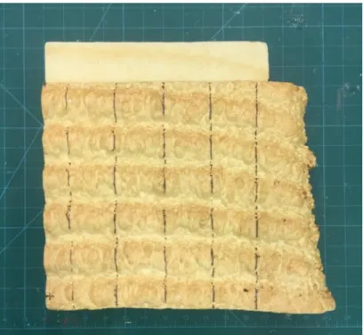
Print-in-To quantify the typical surface textural properties of Print-in-Place fabricated formworks, a 250 mm x 300 mm sample of material printed in-lab using a conventional robotic arm was analyzed in accordance with ISO 4287 [48] (Figure 9).
Figure 9: Print-in-Place formwork sample for ISO 4287 roughness characterization
Five surface profile samples were taken using a Microscribe 3DLX digitizer, with a resolution of 0.48 mm between recording points. While this instrument is dramatically lower-resolution than typical surface topography measurement equipment, it is sufficient for this application because of the scale of surface features of interest on the PiP printed sample. Profile data was analyzed using the MountainsMap surface metrology software package [49]. Profiles were de-noised (50 m cutoff) and then segregated with an 8 mm c filter to separate roughness and
waviness components. Characteristics from all five profiles were averaged, yielding the data presented in Table 2.
Table 2: ISO 4287 surface topography summary data.
Figure 10: Roughness contours, ISO 4287 characterization
This analysis provides valuable insight into the impact of the Print-in-Place formwork surface on the performance and aesthetics of a completed structure:
distance from spray nozzle to print surface; spray pressure; spray flowrate; and nozzle cleanliness. Smoother surfaces have been observed on some prints, although obtaining these reliably through control of the above variables would be challenging.
- Meanwhile, the waviness of the PiP surface is dictated primarily by foam layer structure. In the test sample measured, layer height (which corresponds approximately to Wsm) is
on the order of 40 mm. At this layer height, the total lateral deviation of the printed surface – captured in Wt – is on the order of 12 mm. Further characterization is needed
to explore how changes in layer height and other parameters affect this relationship.
It is important to note that these estimates are likely best-case estimates, since the sample used was printed in optimal conditions (specifically, on a flat print surface) using a much less complex robotic system. Larger-scale components printed with the DCP have been observed to exhibit substantial Z-waviness as well (for examples, see Section 2.2.3), generally resulting from imperfections in the starting print surface. Further work is required to characterize these behaviors. However, these numbers provide a useful starting point for understanding the performance of PiP-fabricated surfaces, and comparing the process to other automated
construction processes. Most usefully, they provide a lower bound on the achievable geometric accuracy of the process, indicating what architectural components can be produced directly with PiP, and what will require additional post-processing via subtractive machining, surface
smoothing or other processes.
Keating’s early experiments, described initially in [5] and [3], demonstrated that this type of post-machining to improve surface finish and geometric accuracy was viable. He also showed that Print-in-Place formworks could be reinforced and finished using conventional ICF techniques; colorized; and even cast into. Most importantly, he conducted basic hydrostatic pressure testing which confirmed that formworks fabricated using Print-in-Place techniques could support comparable pressures to conventional ICF panels. The test specimen described in [3] failed at 53.4 kPa, corresponding to roughly a 2-meter pour of concrete.
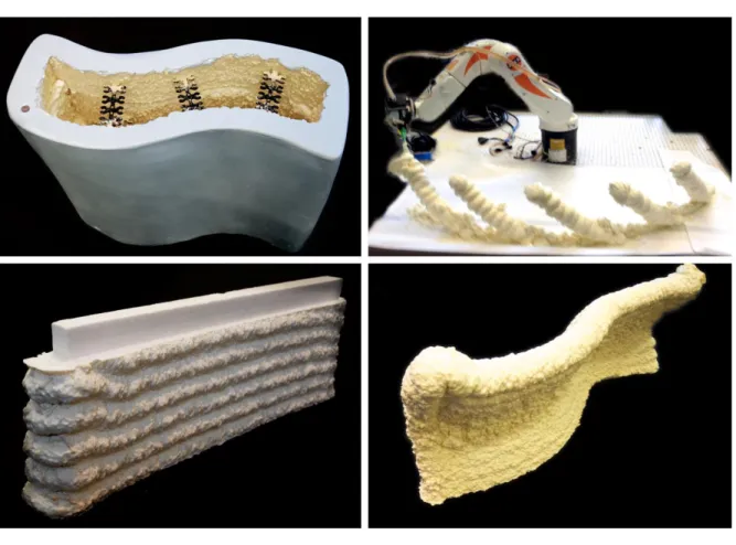
Figure 11: Early experiments with Print-in-Place fabrication. Clockwise from top left: 1) Wall, finished with conventional ICF finishing techniques. 2) Tilted columns fabricated with PiP process. 3) PiP foam can be machined to improve surface finish and geometric accuracy. 4) Example of double curvatures achievable with PiP. Photography credit (all images): Steven Keating. Images a and c originally published in [50].
The suitability of spray foams for additive fabrication has subsequently been validated by a range of other groups in academia and industry. In academia, additive foam has been fabricated at larger deposition widths and faster rates by researchers at the University of Nantes in their BatiPrint3D project, where they report extrudate cross sections of up to 8000 mm2, and feed
high statue of a person using this method, and achieve impressive geometric complexity
including substantial overhangs. Finally, in a more speculative vein, Hunt et. al. have recognized the utility of the low transportation volume of spray foams, and have begun in [53] to explore using them with quadrotor drones to implement additive fabrication processes.
2 DCP v.2 System Development
This chapter describes the first stage of development of a second prototype of the Digital Construction Platform – referred to here as the DCP v.2 – along with a more fully developed motion planning and control tool chain. We then re-implement the polyurethane-foam additive manufacturing process – the “Print-in-Place” process – originally described by Keating in [5], and use this process with the DCP v.2 to produce an architectural-scale, monolithically printed structure.
This chapter first summarizes the system concept, hardware and software that make up the DCP v.2 system, including the pre-existing commercial systems that are used to implement the micro- and macro-manipulator arms; additional sensing hardware used to instrument these systems; and the command generation and control architecture developed to support the system. We then describe a series of different implementations that were conducted with the DCP v.2 system, such as large-scale light paintings, additive manufacturing with polyurethane spray foam, and performance characterization of the DCP v.2 system in accordance with robotic performance standards. Finally, we review the DCP v.2 system’s performance, both in the broader context of automated construction systems, and also to identify specific weaknesses with the architecture that future work should address.
The work described in this chapter was conducted between August 2015 and July 2016, at both MIT and at the Google “Leghorn” facility in Mountain View, CA. This phase of the DCP’s development was led by Steven Keating, and conducted in collaboration with Levi Cai, Selam Gano, Grant Sellers and Damien Martin. Some elements of the work described here, along with some figures, have been published previously, in either Keating [3] or Keating et. al. [2]. Some text has been adapted from [2] for inclusion here, although that text is the author’s original
2.1
System Development
The DCP is a relatively complex robotic system. It incorporates two distinct robotic systems – one commercial, one effectively custom-built – to create a single, highly redundant serial-link manipulator arm. Development of the DCP platform required work at every level of robotic system design, from low-level mechatronics hardware and control code, to high-level task planning and trajectory generation.
This section describes the selection and development of the hardware and software used in the DCP. We first describe the arm systems used to instantiate the micro-and
macro-manipulator arms, along with modifications and additions made to these systems to enable their use. We then describe the control and software architecture used in the DCP between August 2015 and July 2016, known as dcpctrl_v1 [54].
2.1.1 DCP v.2 Hardware
The DCP v.2 system borrows heavily from the DCP v.1 system originally developed by Keating [1], both in concept and in some specific choices of hardware and control modality. Like the DCP v.1, the DCP v.2 is a micro-macro serial-link manipulator arm. The macro arm is implemented using an Altec AT40GW aerial lift vehicle, while the micro arm is implemented using a KUKA KR10 R1100 sixx WP electric robotic arm. Each subsystem is described in detail below.
AT40GW Aerial Lift Vehicle
The AT40GW is an open-center hydraulic aerial lift vehicle, manufactured by Altec Inc. Designed for electrical utility service work, the AT40GW is particularly specialized for operation in confined, limited-access areas such as alleyways and dense environments, offering a narrow footprint, a tracked mobile base, and relatively light total system weight (3,447 kg) [55]. While the reach of the system is considerably smaller than that of Altec’s other aerial lift systems, it is still dramatically larger than that of conventional industrial robot arms, as shown in Figure 12.
AT40GW Kinematics
Kinematically, the AT40GW has a total of six controllable joints, in an RRRPRR configuration (R = revolute joint, P = prismatic joint). Four of these joints are digitally controllable through the PWM interface (described further below). These joints, along with their defined zero positions, are shown in Figure 13 below.
Figure 13: AT40GW controlled joint definitions
Because the AT40GW has been designed as an electrical service vehicle, rather than as a robotic manipulator, it exhibits a number of unusual kinematic features:
- The second joint drives a parallel linkage, such that a rotation of this joint is cancelled by an equal and opposite rotation at the end of the AT40GW inner link. When used as an electrical service vehicle, this allows the AT40GW operator to elevate the main boom arm, allowing the device to reach over obstacles or increase its maximum vertical reach.
However, when the AT40GW is used as a robot the utility of this joint is limited, as its motion is redundant with Joints 3 and 4.
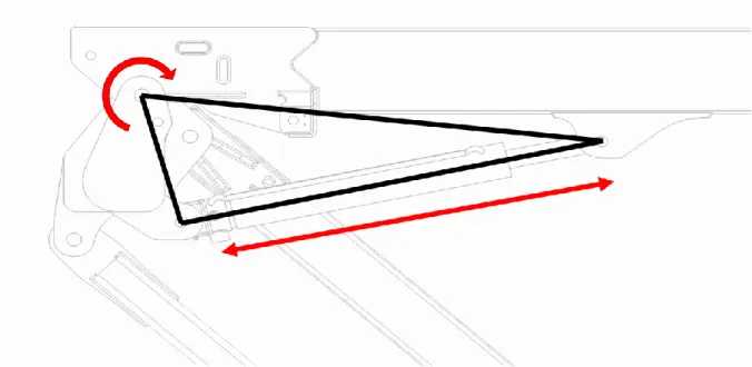
- The third and fifth joints are linked through a hydraulic circuit into a virtual parallel linkage. Any motion at the third joint will be matched by an equal and opposite rotation at the fifth joint, but the fifth joint can be moved independently as well using a
mechanically-operated valve. In use as an electrical service vehicle, this mechanism allows the endpoint of the arm to maintain a fixed angular orientation relative to the ground, avoiding dumping the operator out of the vehicle bucket. In our application, this feature simplifies orientation control of the DCP endpoint, and reducing the amount of compensatory motion required from the micro-manipulator.
To create a kinematic model of the AT40GW, the proximal DH parameter notation
developed by Craig [56] was used. The complete DH parameter set, with link locations and joint definitions, are shown in Figure 14. DH parameter values were initially determined from CAD data, and later confirmed from direct measurements of the AT40GW. To enable use of the J2 joint during path planning, two separate DH frames are used to describe the J2 parallel link mechanism, with the joint angles linked. Similarly, the J3 joint angle is applied to both the J3 and J5 joints to reflect the operation of the virtual parallel linkage structure implemented in hydraulics.
During work conducted 2015-2016, only DH parameters through Frame 4 were measured and used in the control of the DCP. This introduces substantial deviation between the actual and desired endpoint trajectory, since the endpoint trajectory is actually being planned using the Frame 4 coordinate system (the end of the AT40GW boom) as the “endpoint” of the robot. While this was tolerable for the experiments conducted during this phase, it was a major shortcoming of the DCP’s architecture, and was remedied in later work as described in Chapter 3.
AT40GW Structural Dynamics
The AT40GW’s design as a utility vehicle, rather than as a robot arm, also has repercussions for the structural dynamics of the vehicle. As with many micro-macro
manipulators, the AT40GW’s links are too long and flexible to be reasonably approximated as rigid, with even relatively small impulses at the joints resulting in substantial oscillations at the endpoint.
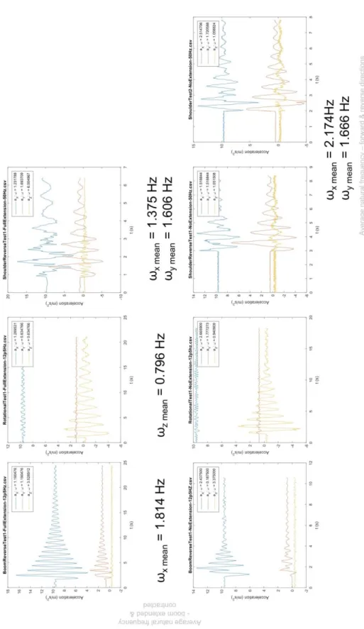
To develop a basic understanding of the natural frequencies of the AT40GW structure and the approximate range of endpoint accelerations exhibited during oscillatory behavior, a preliminary characterization of the AT40GW’s endpoint response to a velocity impulse at each joint was conducted. Tests were conducted on a “floor model” AT40GW system at the 2015 International Construction and Utility Equipment Exposition (ICUEE) show by the author, with support from Altec engineering staff. A mBientLabs MetaWear RPro Bluetooth-enabled accelerometer/gyroscope module was attached near the end of the DCP boom, approximately 140 mm inwards along the boom from the J4 DH frame location, and oriented as shown in Figure 15. Acceleration measurements were recorded using the MetaWear Developer app, at 12.5 Hz or higher and with a measurement range of ±16g.
Figure 15: AT40GW natural frequency characterization – sensor orientation.
Fundamental structural frequencies of the AT40GW in a variety of poses were excited by manually applying impulse inputs using the AT40GW’s hydraulics. This was accomplished by moving the valve position of the joint under test to the full-open position, and then rapidly actuating the hydraulic dump valve from open (default position) to closed and back again, rapidly applying and then removing full pressure from the hydraulic circuit. While this does not produce an identical impulse about each joint, or even a precisely repeatable impulse between tests, it provided a sufficient approximation of the impulse function for this test. The following tests were conducted:
- Excitation about J1 joint, J4 extended and retracted. This test primarily excites lateral vibrations (Y direction in DCP base coordinate system) in the outer link.
- Excitation about J2 joint, J4 extended and retracted. This test excites both in-out and vertical vibrations in the system (X direction and Z direction in DCP base coordinate system), mostly in the inner link and J2 joint.
- Excitation about J3 joint, J4 extended and retracted. This test excites vertical vibrations (Z direction in DCP base coordinate system) in the outer link.
Results from these tests may be seen in Figure 16, and are explained further below. It is
important to note that the coordinate system used by the MetaWear RPro – shown in Figure 15 – has a different orientation than the DCP’s base coordinate system (where the Z axis points along the axis of the J1 joint, and the X axis points towards the end of the AT40GW boom when in its stowed position).

![Table 1: Material performance data for Dow FROTH-PAK™. Some data taken from [47]](https://thumb-eu.123doks.com/thumbv2/123doknet/14733220.573527/39.918.217.703.150.556/table-material-performance-data-dow-froth-pak-taken.webp)
![Figure 25: DCP trajectory generation workflow. Image credit: Steven Keating. Image originally published in [2]](https://thumb-eu.123doks.com/thumbv2/123doknet/14733220.573527/69.918.120.800.321.644/figure-trajectory-generation-workflow-steven-keating-originally-published.webp)
