Publisher’s version / Version de l'éditeur:
Vous avez des questions? Nous pouvons vous aider. Pour communiquer directement avec un auteur, consultez la
première page de la revue dans laquelle son article a été publié afin de trouver ses coordonnées. Si vous n’arrivez pas à les repérer, communiquez avec nous à PublicationsArchive-ArchivesPublications@nrc-cnrc.gc.ca.
Questions? Contact the NRC Publications Archive team at
PublicationsArchive-ArchivesPublications@nrc-cnrc.gc.ca. If you wish to email the authors directly, please see the first page of the publication for their contact information.
https://publications-cnrc.canada.ca/fra/droits
L’accès à ce site Web et l’utilisation de son contenu sont assujettis aux conditions présentées dans le site LISEZ CES CONDITIONS ATTENTIVEMENT AVANT D’UTILISER CE SITE WEB.
Report (National Research Council of Canada. Division of Building Research), 1954-11-01
READ THESE TERMS AND CONDITIONS CAREFULLY BEFORE USING THIS WEBSITE.
https://nrc-publications.canada.ca/eng/copyright
NRC Publications Archive Record / Notice des Archives des publications du CNRC :
https://nrc-publications.canada.ca/eng/view/object/?id=37b1ca30-ff6e-4522-900a-b049267f1e6e https://publications-cnrc.canada.ca/fra/voir/objet/?id=37b1ca30-ff6e-4522-900a-b049267f1e6e
NRC Publications Archive
Archives des publications du CNRC
For the publisher’s version, please access the DOI link below./ Pour consulter la version de l’éditeur, utilisez le lien DOI ci-dessous.
https://doi.org/10.4224/20386604
Access and use of this website and the material on it are subject to the Terms and Conditions set forth at
Report on "Homogeneous Wall" House Experimental House no. 4 Ajax, Ontario
NATIONAL RESEARCH COUNCIL CANADA
REPORT ON "HOMOGENEOUS WALL" HOUSE
EXPERIMENTAL HOUSE NO.
4
AJAX, ONTARIO by
S.A. Gitterman
SupervisorJ Architectural Department
Central Mortgage and Housing Corporation and
DoB. Dorey
Building Design Section Division of Building Research
National Research Council
セnaャ YZED
(Prepared for Central Mortgage and Housing Corporation)
November,
1954
DBR Report No.
30
of the
Division of Building Research Ottawa
PREFACE
.
-The Division of Building Research of the National Research Council is privileged to act as research wing to Central Mortgage and Housing
Cor-poration. It is therefore a special pleasure for
the Division to publish this report on a project which was initiated and carried out entirely within the Corporation and with which the Division had little to do beyond playing the part of interested observers.
The report is published by the Division and in this way since it forms one of a series of internal reports which the Division has been
pub-lishing and into which it fits conveniently. It
is hoped that the experience recounted in this report will lead to further development by Joint work on the part of both organizations.
Liaison between the Division and the
Corporation is maintained through
Mr.
I. E.Ashfield, Supervisor of the Technical Department
of C.M.H.C. The Division wishes to acknowledge
with appreciation the assistance of
Mr.
Ashfieldand of
Mr.
Gitterman in connection with all aspectsof the preparation of this joint report.
It must be noted that no part of this report can be reproduced in any way without written authority from either the Corporation or the Division.
Ottawa
REPOHT ON IIHOMOGI2HEOUS 1,-fALL" HO rrSE
EXPERIMENTAL HOUSE noセ 4
AJ AX$ ONTlUlIO
by SoA .. Gitterrna..."'1 and 1.J0 B " Dorey
In
1948
3 Centra.l Mortgage and Housing Corporation", awareof the need for Low-co at housing in Canada to meet the increasing
demands of the ーッウエセキ。イ ケ・。イウセ propo8ed the erection of four
experimental ho us e s at; Ajax9 Ontario, one of whi;:;h ...ras to have a
wall construction different from any system used thus far in
Can-ada or in the United States. The aim of this new design was to
investigate an assembly techrlique where the success or ヲ。ゥセオイ・ of
the system depended on the use of a single material or two materials
if necessarYi in the place of a conventional wall &3801fuly.. It
was generally thought that if' such a material co u'l d be found and this material could be bonded together by a simple fusing operation to form a wall; then this new method of home building might succeed in reducing construction costs ..
The construction of a conventional wood-if'r-ame wall... and
all known prefabricated wall systems to date? ;involve numerous
and t.Lme-vconsumf.ng operations. The materials used are often
man-ufactured at Widely di.fferent geographical points and are costly
to transport. An improvement in the ーィケウゥセ。ャ ーイッー・イセゥ・ウ of one
component of a composite wall may improve the qaality of that wall
but it does not eliminate the factors of workmanship9 time9 or
number of operations. Speed of erection was acha e ved during the
war years by prefabricating and precutting materials but construct-ion costs were not reduced appreciablyo
An acceptable wal19 regardless of the combination of ュ。エセ
erials or the system of coristr-uct Lcn , must be strong and rigid and
possess resistance to heat transfer) moisture エイ。ョウヲ・イセ and fire
as well e» havLng a pleasing appe ar-anc e , It would appe ar , therefore,
that if a homogeneous material could be ヲoGNャゥセ、 or developed that
would serve all these functions at one time and this material could be produced cheaply and on a simple and continuous mass production
basis9 progress would be made in meeting the demand for low-cost
housing o
A diligent search revealed that there wad no material
avail-able with all the properties イ・アオゥセ・、ッ One of the more important
considerations in selecting a material or ma!;erials wa:; to find
one9 or twoD possessing properties which would not be detrimental
to possible success of the proposed assembly techniqueo
After considering all the known materials available for the construction of this new type of house.\l Pittsburg Corning Foam-glas was decided upon as being the closest approach to a suitable
2
-fire resistant, impervious to moisture and is easily bonded
to-gether or to other materials. Blocks are ma.nufactured and sold
in sizes of 12 by
18
inches and can be obtained in thicknessesof from 2 to
5
inches. This material lacked9 however-セ one ゥューッイエセant characteristic for this experiment; strength. It is ヲイゥ。「ャ・セ
brittle, and has little impact resistance.
At first it was thought that 2 inches of foamglas 」ッオセ、
be combined 1tJith 2 inches of "c eLl.boar-dセゥL to form a. wall with a
total thickness of 4 inches. Later it was ヲッオョ、セ ィッキ・カ・イセ that
when the two materials were bonded together and stored outside,
the cellboard deteriorated. It was therefore decided that two
thicknesses of foamglas should be used and that the cellboard
should be omit '.
2. Final Plans for the Erection of P.C. Foamglas House
(Experi-mental House No.
4)
Final plans were completed and approved by Central Mortgage
and Housing Corporation in December
1948
for Experimental HouseNo. 4 to be built at the industrial community of Ajax9 ontario,
under the supervision of the regional office at Toronto. A plan
of this house is shown in Fig.
7.
A basementless house was chosen for this investigation consisting of two bedrooms, bathroom, combination dining and
living room, kitcheng and utility room. Time and motion studies
on the erection operations were proposed as a. necessary part of
the investigation so that the costs of セィ・ various operations could
be studied. Further to the studies ュ・ョエNゥッョ・、セ it was proposed
that the investigation include studies of the performance of the
concrete slab, the structural components, the thermal characteristics,
and the general acceptance of the structure by tenants.
Observat-ions were to be made by both the tenant セャ、 members on the staff of
the regional office of Central Mortgage and Housing Corporation at Toronto.
The foundation was to be a floating concrete slab with
heating ducts cast integrally with the concrete. The heating unit
was to be of a type which could be installed in the base of the
chimney. The walls were to be constructed of 4=inch
prefabri-cated foamglas panels, treated on the vertical construction joint edges with a fusable material, and on the interior and exterior
ウオイヲ。」・ウセ after erection, with a scrim set in ordinary oil base
paint to improve the strength, appearance? and rigidity. The doors
and windows were to be of a split frame design so that they could
be clamped in their respective openings "],;'1...:lminimum of effort.
The roof was to be constructed of prefabricated panels made up
from 2- by 6-inch joists with solid bridging and a
1/4
inch plywoodupper surface to support the bonded roofing and roof live loads. These panels were to be insulated with mineral wool between the
Lセ 3 =
finishes were to be eliminated where possible; the floors of the rooms were to be of concretee
The object of this investigation was not to test the
substitute material specifically, but to determine キセエィ・イ the
basic ideas and the cc.ncept of using unskilled labour in the
assembly of the house could be successful e
30
Construction of セ・イスュ・ョエ。ャ hッオウセセセセFoundationg= The construction of the foundation began in the
fall of
1948
0 The top soil was removed from the site topredeter-mined elevations and the area under the foundation was backfilled
with sand and gravel to the respective gradeso With this operation
completed v the forms were put lnv the water and sewage connections
were made» the felt paper was laid" and セィ・ concrete placed e
During and after the curing of the concrete tarpaulins and straw
were used to protect it from freezing temperatureso
The foundation consisted of a floating concrete slab with
perimeter beams e The concrete was proportioned to give an ultimate
compressive strength of 2500 Ibo per sq. ino in 28 dayso The slab
inside the perimeter beams has an overall thickness of 6 inches$
reinforced for temperature only wi th Vセ by VセGゥョ」ィ '.' 12/12 woven
wiroe mesh e The perimeter beams are reinforced longitudinally
with
4
QORセゥョ」ィ diameter plain reinforcing bars and 6= by 6=inch-12/12 W.We mesh which extends to the outside edges from the centre
slab. The QPセゥョ」ィ diameter heating dacts and outlets were cast
integrally with the foundation o Moisture is retarded from entering
the underside of the slab and perimeter beam by 12'·lb o felt paper. The outside edges of the foundation are insulated with a strip of
p. Co Foamglasv 2 inches thickv extending from the top of the
foundation to a depth of 20 0 0 feet. Outside of the PeCo Foamglas
there is a strip of asbestos-cement board extending in width from
just below the top of the slab to a depth of
8
inchese The slabis supported by a layer of gravel 1 to 2 inches deep under the
slab and
6
inches deep under the perimeter beamse Under thegravel there is a layer of sand 2 inches deep at the rear of the
house and 16 inches deep at the fronte The combined action of the
grading from sand to gravel is intended to prevent moisture from
moving upward by capillary action to the slab. The slope of the
base of the sand bed is to cause the moisture, if anyv to move to
the front to a drainage pit a.pproximately
3'
x Tセ・ Figure8
showsa 」イッウウセウ・」エゥッョ of the foundationo
External w。ャャウZセ The 'side walls were erected in the fall of
1949.
At this timeII the panels were taken from the carefully planned
stockpilev the crating was removed from the edgesv and they were
erected one by one" The orderly plan of erection involved the
4
-the interior partitions were put up at -the same time to form a
room or a cell. This procedure made it easy to make the walls
plumb and gave continual stability to the completed portion of the walls.
The perimeter walls are made up of Tセ by 8=foot by 4-inch
P.C. Foamglas panels which were prefabricated on jig tables from 12- by 18- by 2=inch PoC. Foamglas blocks bonded together by
mopped asphalt compound by unskilled workmen. The joints between
the blocks were staggered to assure an overlap. Window and door
openings were made in the panels as they were fabricated. The
edges of the panels where vertical construction joints were to be
made during erection were coated wi th ecセGURTAI 113M Adhesive and
Coating"$ thermoplastic compound which can be reactivated after
it has hardened by applying heat. The exposed edges of the panels
were protected by wooden crating during transportation and stock-piling.
The panels were bonded to each other vertically by re-activating the thermoplastic coatings on the edges with heat by
a specially designed heater. The procedure using the ・セ・」エイゥ」
heater was to bring the edges of the panels close together,
insert the heater between the edges and prevent heat from escaping from the back with a wood strip placed vertically over the open
joint, reactivate the thermoplastic coating, remove the heater and backing strip, and shove the one panel against the other manually.
The panel could be aligned with the wall キセゥャ・ the adhesive compound
was setting. Since this jointing compound sets quite rapidly,
fix-ation and alignment occurred at almost the same time. After the
joint had set!) the two panels thus joined would form a rigid surface.
The methods used in bonding the panels together are mown in Figs.
1 and 2 respectively.
The panels were bonded to the floating concrete slab by another type of adhesive compound (Flintkote) having slower setting qualities thus allowing sufficient time for vertical jointing.
This compound was applied along the line of the wall just before each panel was raised to a vertical position so that it would provide a seal against moisture coming in at the joint and bond the wall to the foundation.
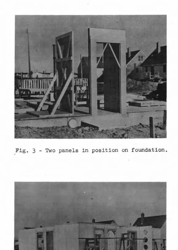
As previously emphasized!, the erection of the house
fol-lowed a certain sequence. This procedure was as follows: the first
panel was raised in position on the line of the wall using a tri-angular cross-sectioned wooden strip9 bonded to the foundation as a guide for alignment at the base of the wall, (two panels are
shown in position on the foundation in Fig.
3),
the second panelwas brought to the proper position, bonding compound (Flintkote) was put on the foundation where the panel was to be placed, the panel was raised, jointed vertically!) and lined up with the
- 5
=walls were in positionD bonded to each other and to the foundation
as shown in Fig. 40 vfuere an interior partition intersected an
outside wall, the vertical construction joint was used as in
bond-ing the edges of two panels together.. Protective crating was left
in place around the doors and windows until these units were in-stalled.
Partition w。ャャウセセ The interior partition walls were
pre-fabricated 。ョ、Gセ erected in the same manner as the outside walls.
As mentioned beforet they formed a definite part of the cellular
construction technique in providing stability during and after
erection.. Interior access doors were made in the panels as they
were prefabricated.
Wall fゥョゥウィ・ウセ - Before erection9 the ウオセヲ。」・ウ of all
partition and exterior walls were covered with scrim set in
ordinary oil base paint over wInch one coat of paint was applied. Second coats of paint were added on the inside and outside walls
for aesthetic reasons.. "Gyptex?l was applied to the interior walls
as a decorative finish and oil base paint was applied to the ex-terior walls ..
Floor cッョウエイオ」エゥッョセ - The floors in all the rooms were finished
with pigmented concrete, ヲャッ。エ・、セ and finished to the desired
smoothness.
ceilin, Construction; - The ceilings in all the イッッュウキセ finished
with
3
8-inch "Gyproc'f sheets fastened to the und ez-s Lde of the roofー。ョ・ャウセ jointed in the usual manner!} and painted with "Gyptex". All ceilings have a slope equal to that of the roof ..
Roof Const r-uct Lon s = The roof is made up of prefabricated panels
adheredWithP. slow setting adhesive compound to the top edges of
the interior and exterior walls.. The slope is 1/8 inch to 1 foot ..
The weatherproofing material on the roof is bonded roofing ..
Each panel was prefabricated from Rセ by 6c > i n c h and 1/4-inch
plywood.. The spacing of the 2= by Vセゥョ」ィ joists in all panels
except two is 16 inches c ent.r-evto-ccent.r-e , The remaining two have
joists on 12 inches 」・ョエイ・セエッ]」・ョエイ・NN Solid 2- by 6-inch bridging
was used to prevent buckling of joists and 1/2=inch plywood was nailed to the upper surface to support the dead and live loads.
The ends of each panel have 2=, by 6-inch headers to mich the
longitudinal joists are butted and fastenede
Tapered wooden members form the セNッー・ of the roof.. These
members were shaped and bonded to the top of all walls with a slow setting rubber base cement (Flintkote).
The roof panels were taken from an orderly stockpile and
6
-into position on top of the walls. Each paneL In sequence was glued
to the tapered members. At the rear wal.l, the joists rest directly
on the F'oamglas wall. A plan of the roof assembly is shown in F'igo
90
Windo'VI: Construction: - The windov.TS and frames were made up on special
request to the manufacturero The frames and sashes are of aluminum
and were designed to have two sections, and inside and an outside section. During assembly, the wood cratings wer-e removed from the
open-ings and the window units were clamped in the openopen-ings. Both sections
were inserted from their respective sides of the wall and were clamped
ヲゥイセャケ in tho opening, thus forming complete, quickly assembled units.
Door Construction: - Doors and their respective frames were
pre-fabricltl.ted on the same principles as the window units. '1'he mat er-LaL
in this case, however, was woodo
As with the window units, the door "illlits were assembled in
their respective openings in the same manner, the only difference which
may be noted is in the ュ・セィッ、 of fastening the inside and outside
sections together.
HeatinG: " Heat is supplied to the various rooms by a
Mortemp, forced air, oil furnace installed in the base of the chimney0
Warm air frorn the furnace is circulated through ducts 10 inches in
dia-meter cast in the peridia-meter beams of the concrete foundation. Floor
surface registers under the windows distribute the warm air to the
in-terior. The heating system was desiened to minimize cool areas in front
of windows by regulating the registers. In the bathroom, however, the
register was installed at the base of a partition wall instead of under
the window. Zone heating control is possible by manipulation of the
dampers which were installed in the warm air ducts near the source. A
circulating fan near the ceiling returns air to the furnace. A plan of
the heating system is shown in Figo 10.
Plumbing: - The plumbing system is of conventional design
ex-cept that the piping below the floor level was connected in the planned
position before the foundation was casto Regular water and sewage
con-nections were made when the foundation forms were put in.
Electric Wiring: - Because of the experimental nature of the project,
the electric wiring was to be surface mounted. This plan, however, was
not followed. All the wiring is concealed in the walls by making small
trenches or channels in the P.C o Foamglas. After the セゥイゥョァ was embedd i
small pieces of foamglas were ca.refully fitted over the wiring and
covered by a paste to give a flu3h ウオイヲ。」・セ vfrlere an outlet, fixture, or
switch occurred a square recess was made in the wall and a wooden block was fixed in pla.ce with the quick setting adhesive compound used for
vertica.l jointing. The junction boxes or fixtures were then fastened to
the blocks in the same manner as in conventional wood houses.
Interior: - The interior finish consists of window and door
casings and ogee mo u.idln.; around the ceiling in the living room. Instead
of putting baseboards around the rooms, the walls were painted around
the bottom to a height of
4
inches with a paint the same colour as the7
-Exterior tイゥュセ セ ExteTior trim was applied around the doors and
cornice only. Other forms of trim usually ヲッセセ、 on conventional houses
were intentionally omitted.
Flashing: セ Flashing was installed on the outside joints at
the base of the wall.
Kitchen c。「ゥョ・エウセ - Kitchen cabinet units were prefabricated and
transported to the slte. The 」。「ゥョ・エウセ as well as the bathroom fixtures,
were placed in position on the slab and the panels erected around them.
4.
Observations Made During ErectionNo objectionable difficulties were encountered in the erection
of Experimental House No.4. All the components were assembled by
supervised workmens unskilled in this type of work, in a short period
of エゥュ・セ
Time records were kept of the construction and it is interesting to note that the house was completely enclosed in sixteen hours by six
workmen unskilled in this type of work, twelve hours for the wall9 and
four hours for the roof. This time include8 only that required for the
erection of the I,refabricated units.
The ャゥァョエセ 3ight wall panels were easily handled and transported
from the stockpile to where they were used. Rehandling of wall and
roof units was unnecessary because all these elements were pre=arranged in the stockpile.
In the erection of the vertical components, the P.C. Foamglas panels, the first method of applying the bonding compound to the joints
at the base of the wall was changed. It was initially intended that
this compound would be brushed on the foundation befvre a panel was erected in much the same way as paint is brushed on a flat surface. This procedure, however, was fOillld to be too alow in comparison to the
ease with which the other operations were performed. The technique
adopted was for one workman to pour the viscous compound slowly into a small trough held by a second workman who directed the flow along the
wall line. The deposited cOlnpound was then spread evenly over the
sur-face of the foundation 'where the panel was to be placed. The slow setting
nature of this compound allowed the workmen sufficient time to reacGivate the coatings on the vertical edges of the panels and complete the
vert-ical jointing before it set. Prior to erection, a specially designed
electric joint heater for reactivating the ecセURT thermoplastic compound
was made up. Although the heater was easy to use, the output of heat was
not sufficlent to let the vertical jointing of the panel progress swiftly and ・ヲヲゥ」Q・ョセN If this heater had been designed for a larger output
of heat9 it is thought that it would have expedited erection operation
considerably. The general features of this heater are shown in Fig. 20
The unique design of the door and window units made it POSSible for workmen, unskilled in this work, to install them quickly
= 8 ,.
and easilyo Additional time could have been ウ。カ・、セ ィッキ・カ・イセ if
the wooden units had been painted at the time of fabrication
instead of after they were ゥョウエ。ャャ・、セ
One of the innovations in this project was the omission
of mouldings where they normally occur in conventional constructiono
The omission, wherever possiblev of all interior and exterior
trim removed the necessity of employing carpenters o In some
instances mouldings were put on for aest.hetic reasons" This
increased the cost as they were not an anticipated part of the investigation o
Uセ Performance Record of Experimental House No o
4
When construction was 」ッューャ・エ・、セ a structural safety
analysis was made by the Architectural Department of Central Mort=
gage and Housing cッイーッイ。エゥッョセ From the results of these 」。ャ」オャ。エセ
ionsj the house was assessed as being safe for occupancyo A
tenant was found who was very interested in the project and after
being thoroughly informed of the aspects of the experimentv he
formally agreed to occupy the house and make periodic reports on its performance from a tenant's viewpoint"
The キ。ャャウセ which were considered to be the most critical part of the house, have shown no signs of structural failure to
、。エ・セ from snow accumulating on the roof or from high velocity
キゥョ、ウセ or a combination of both o d。ウーゥセ・ the fact that there is
only a ャセ by 4-inch bearing strip to transfer the roof loads to
the rear wall there has been no indication of crushing in the
foamglas where the strip is bonded to the wallo The rigid cellular
construction and joint fixation have no doubt contributed to the
satisfactory withstanding of the loadings o To the knowledge of
the キイゥエ・イウセ this type of mat ez-LaL has never been used exclusively
as a structural material 「・ヲッイ・セ and it has performed wello
An
interesting ゥョ」ゥ、・ョエセ worth relatingv happened shortlyafter this house was erectedo Having no idea of what damage they
might 、ッセ a group of seven workman elected to hold a conference;
the site chosen for the discussion was the inviting flatness of
the roof of this house" Although there was some question as to
what the reaction would be on the houser the group held its
discussion on the roof without any evidence of adverse affects on the structure"
In addition to winter and summer climatic extremes9
structures in this region are subjected to high wind .. and
ウョッキセャッ。、ウB In spite of these loads, however9 there has been no
evidence of structural failure on the roofG The large overhang
at the eaves of this house would suggest that adequate fixation against uplift has been maintained by the bonding between the walls
and the roofo Minute cracks have occurred around the ceiling but
セ 9 ••
From the late fall of 1948 unt I I the erection of the
re-mainder of the structure in the fall of
1949,
the foundation wasprotected from adverse weather conditions by tarpaulins and straw. There were no signs of cracking in the concrete when the house was
occupied. Hairline cracks did occur in the top surface of the
foundation, ィッキ・カ・イセ immediately above the heating 、オ」エセ in the
utility room and across the door openings in the outside walls, but
have not enlarged. The tenant reports that all doors and windows
function properly indicating that there has been no shifting or differential settling.
This wall material has been widely used as an insulating
material. It isp therefore, a very good material for side wall
construction from a thermal viewpoint. With adhesively bonded
joints on all edges of the ー。ョッャウセ the greatest heat loss can occur
only at the joints and around windows and doors. Being a
homo-geneous material, the paths for heat transfer a0ross the temperature potential are almost entirely eliminated.
Heating cost records show that Experimental House No.
4
isthe most economical to heat of all the houses of similar size in
the area. The tenant reports that only in a very cold month does
he use more than eighty gallons of oil. A suggestion as to why
this house has proved to be more economicai to heat than the conventional wood=frame houses is that the walls are constructed from one material having a constant thermal conductivity factor
(0.15)
and that all the joints are of bonded construction. The thermal conductivity factor of the conventional vlood=frame housesin the area is calculated to be 00
09)
obtained from the independentvalues of the components making up the conventional wall. It does
not allow for po.:.;siblo shrinking and warping of lumber caused by exposure to the weather or 'workmanship which might permi t added air infiltration.
As ーイ・カセッオウャケ ウエ。エ・、セ the heating ducts were cast in the
foundation. The tenant has reported that a noticeable teat loss
occurs through the ウャ。「セ evident during the winter season when the
ground surface is covered with snow. The tenant reports that when
snow was present elsewhere, the ground around the house was bare for
a distance of four feet at the frontD or south side, and for a
distance of approximately two feet on the other sides. He also
reports that pansies were in bloom at the セセッョエ door long after they
had been f'r-ost e-kd Ll.ed e Ls evher-e , The tenant's report was dated on
January
15, 1952,
and in it he stated that he could sec a smallpatch of clover .. "aLdve and green", a foot from the south wal:'o
A very interesting characteristic of this house is that in the summertime an excessive condition of humidity exists inside the
house. It would seem that because of the impermeable nature of the
materials in the walls the moisture in the enclosed air is retained
" 10 ,.,
As the three other ho us e s of c onv ent.LonaI wood coristr-uc t.Lon , whf ch
were built at the same time and on similar ウャ。「ウセ do not have this
condition in summertime: it is thought that the vral Ls of the f'Lber-»
glas house are the 」ッョセイゥ「オエゥョァ media to the excessive condition
of hum.ld I ty0
Further to the resistance to neat transfer qualities!, this material has favourable physical qualities in resisting moisture
penetration. It is a relatively inert substance. The only signs
of moisture penetration have been at the joints of panelso At
points where moisture did find its way セィイッオァィ[ caulking compounds
were applied as an immediate ウッセ⦅オエゥoャャ to the problem but not neces=
sarily as the only means of stopping the lnfiltrationo
There was a second example c.f moisture Lnf Ll t.r-at.Lo n , Instead of filling the exterior wall joints with a masti8 」ッョセッオョ、
and covering them with a strip of cloth set in paint. as specified! the workmen in their enthusiasm to do neat work on the wall joints used gypsum plaster and a paper tape Vlhi.:.h was not suitable for
exposed surfaces. When leaks eventually occurred in the outside
wall ェッゥョエウセ the joints were repaired by cutting a channel in the
foamglas at a depth of
3/4
inch and a wid::h of3/4
inch on eachside of the jointo This channel was then filled with mastic and
very few subsequent leaks have occurredo
Other small leaks o ccur-r ed around architraves and it was
learned that the rubber and mastic ゥョセッ which the frames were to
have been clamped during assembly had not been applied to all the window frames and 、」ッイセ as specified.
Condensation trouble developed soon after r.ne house had
been occupied3 During heavy rainostorms a large pool of water
would collect 。セ the northeast corner of the house arrl seepage
from this pool would find its way through to the heating ducts where it would accumulate to a depth of 3 inches at SOI'Qe times .. The warm air cirCUlating through the heating ducts would gather moisture from this water and carry it to the interior where
condensation would occur on the bedr-oom floors Q This difficulty
was overcome by installing e av e st.r-oughi ng and a line of drainage tile under the driveway at the north93.st:,orner of the hou3eo
No o t.her signs of moisture penetration through the foundation have been reportedo
6. Summary of Costs of exr・イゥセ・ョエ。ャ House Noo セ
The costs of the various constru0tion operations were
recorded for each of the four experimental houses ・イ・」セ・、 at
Ajax as an important source of information in this investigation. These costs were recorded and classified as nactual" costs and
"potentialTI costs for Experimental House No , 1-1-0 The a ct uaL costs
セ^ 11 '"'
the erection of Experimental House NOe Tセ but do not include the
administration costs or the cost of producing the plans. The
word "potential" is used in a restricted sense to describe the costs that were not peculiar to the experimental development of ideas or to the reduction in costs which might ba possible if this house were to be reproduced in the same manner by an
experi-enced crewe The actual and potential costs computed are shown
in Table I» with an additional column showing the reduction applied
to the actual costs in computing the potential costs. TABLE I
Actual Costs Versus "Potential" Costs at Same Unit Costs
Actual Cost ($) Excavation Foundation Scaffolding Millwork Wall Panels
Roof Panels (Supply
&
Install)Bul.Lt.e-up Roof Plumbing
Heating
Electrical Installations
Painting (Interior
&
Exterior)Redecorating
Cold Air Wall Ducts Oil Tank
Oil Tank Slab
Extras=Repairing Deficiencies General Conditions Special Equipment Cartage TOTAL Potential Cost ($)
95.58
1297«>04
9075
1120.73
2082.75
1026.23
154.00
,530.00
481.00
215.00
225.00
80000
38.1.8
.35.00
200
0 0 050.00
Reduction443.46
309.31
4685.26
3.35
30
0 0 085.00
169.00
142
0 0 0283.00
289.80
36.00
The amounts appearing in Tab:e I under the heading
"Reduction" include the costs of trial installations and
develop-ment work. The actual costs for the wall panels LncLud e the labour
costs for making up the panels and for fitting them around plumbing
pipes and for concealing the ・ャ・」エイゥ」。セ wiring in the foamglas.
A comparison of the costs of the various construction operations for the four experimental houses at AJax is shown in
roe 12 -TABLE II Ajax eセNNeN・イゥュ・ョエ。ャ Units Comparison. of Costs Item No .. 1Unit ($) Unit No. 2 ($) Unit Noo 3 ($) Unit No"
4
($)289.. 80
86.. 00
483.00
38.. 18
35 .. 00
80,,00
95.. 58
1740.50
9.75
1430
044
154,,00
1029058
6768 .. 01
50,,00
200.00
38.18
35.00
80,,00
USPNPセI
560,,00
215 .. 00 300,,00481,,00
481,,00
(169,,00
225,,00
(225.00
(4)95.. 58
1297,,04
9 .. 75
1120,,73
154.00
1026 .. 23
2082.75
171 .. 79
187.. 01
160.99
1049071
1187058
1158696
100.9374..
24
76062
1471+097
1450.04
1359.06
1527062
1219.03
1879.69
151 .. 56
130 .. 59
129.88
116059
151.34
131.,19
461.96
394.51
348 ..
QSセ 300 ..
47
359 .. 82
266.. 52
170 .. 64
220 .. 64
20.30
165 000
260.. 00
,563
e00
542.00
520.00
214.50
209000
197.50
.360 ..
95
33t· 61
325 .. 03
342
00 028 .00
260..00
660016
64.48
60.1636.75
40 .. 00
35 .. 45
986.00
986 000
986
0 0 038 .. 18
38.18
38 018
Excavation Foundation Masonry Rough Carpentry Millwork Insulation Roofing Roof Panels Interior Walls Exterior Walls Finish Flooring Mastic Tile Plumbing Electric Wiring Heating Painting Hardware =, Nails Finish Hardware Special Equipment Ca)'tage (1 General Condition Oil TankOil Tank Slab Cold Air Ducts
TOTAL(2)
---
⦅N⦅MMMMMMMMMMセN⦅MセGeneral Conditions for Nos" 19 21 and 3 includes Cartage and
Supervision.
Not included above is a fee of
$600.00
per house paid to thecontractors.
Reductions in electricity and pl un.... _セ costs are arbitrary.
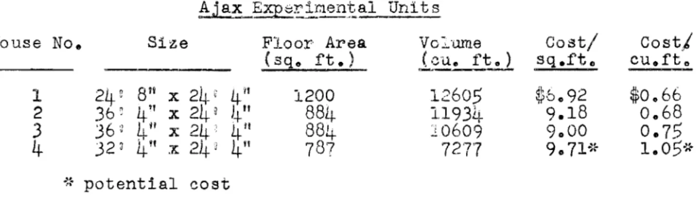
Table III presents the cost per square foot of floor area
and the cost per cubic foot of volume for each of the four
ex-perimental 'waits.
TABLE III
House No. Size Floor Area Vo Lume Cost/ Costi
(sq. ft. ) H・オセセ sq.ftCl cu.ft .. 1
24
rr8
11 x24'
4/1
1200
12605 セVcQYR'h$0.66
2
SVセ4"
x24
l 1-1-"884-
11934
9.18
0.68
3
SVセ4"
x24
4"
88420609
9.00
0.75
4-
32
J \ It x 2)+J4"
787
7277
9.
WQセセ1.05*
4-..
potential cost セセThe floor plans for Experimental Houses Nos. ャセ Rセ and
3
areshown in Fig. Nos. lID
12
and13
respectively.Experimental House No.4 was lower in cost than the standard
types of houses in such items as masonry , r-ough car-p entr-y, mfLl.wor'k ,
ゥョウオャ。エゥッョセ and painting. A direct 」ッュー。セQウッョ between these items
and those in a standard type of house is somewhat misleading" ィッキセ
ever.? for in some cases there was a transfer of costs from one item
to another. For instance" masonry was practically eliminated from
this house but a steel chimney installed as part of the heating system
increased the cost of the heating ゥョセエ。ャャ。エゥッョhセ also; insulation"
which is usually installed in the walls and ceilings of a conventional house in the form of batts placed between the studs and joists) was
a physical characteristic of the wall material. Millwork costs were
slightly lower than for the standard types. Rough carpentry dis=
appeared almost completely except for scaffoldingo
Items in Experimental House No.4-which coat more than correspondlng items in the standard 'type of house were the found-' ation D roof" interior and exterior wal.ls, and installat5.ons of heating.? plumbing D and electricity.
7.
セオュュ。イケ of ResultsTo dat e , it has been found that Experimental House No.4
has performed essentially in the same manner as a conventional house.
From the records now on file at Central Mor-:;gage and Ho u sLng Cor-p»
oration" it ha.s been established that the heating costs over any
given period of cold weather were less than for any other conventional house of similar size in the Aja.x area. The faot that this house has
shown no signs of structural failure since its erection would indicate that it is of sufficient strength and rigidity to withsta.nd the dead loads and superimposed live loada to which it has been subjected.
- 14
=A r-evi.ew of the erection r-eccr-d s show that the number of operations
in the pr3fabriGation and the erection of the wall panels by
un-skilled labour to obtain a w'all that would approach an equivalent
conventional walJ_ were simple and few Ln number , The technique
of erection by bonding compounds proved to be fast and efficient o
It is of further interest to note that all the ーイ・ヲ。「イゥセ
cated componentst except those forming the roof, were assembled
to form "thts house without using spikes or nails or hardware
f'ast ener-e of :;hat sort , All the joints were fastened with selected
bonding c ornpounds 0
The diff.i.culties encountered were a result of the ・クー・イゥセ
mental nat-ur-e of the imrestigation and wouLd not recur when
suf-ficient exp er-Lence in this t.echrdque of construction was gained ..
This invesigation has shown that with the material used9 it should
be possible to construct his dwelling at a cost comparable to the
cost of a conventional dwelling.. To produce a house comparable
to a conventional dwelling at a lower costf ョッキ・カ・イセ a less ・クセ
pensive mater-ial must be found セセ one that could be mass produced
in modular sizes .. BibI i 0§;.rセNeNNyN
AlgrenD A.. B, Ground Temperature Distr::_bution with a Floor Panel
Heating Systeme Heatingp Plping9 and Air Conditioning. vPRPセ
NOe
5
ppo 111=116& May, 19480Baracos., Ao
Foundations Division of May,
1952.
A Study of Basementless Houses on Concrete Slab
in Central Canadao National Research cッオョ」ゥャセ
Building Research. sエセ、ケ Report No o
27,
Ottawa.bイオ」・セ Alfred, and Harold Sandb&bk. A History of Prefabrication.
John B, Pierce FoundatLon, Research Study'
3.
Third Printing.September [
194-50
-Dill, Richard S., William So Robinson, IDld Herwy Eft Robinson ..
Measurements of Heat Losses from Slab Floors. U.. So National
Bureau of Standa.rdso Building m。エ・イゥ。ャセ and Structures Report
1030 Washington o March QPセ
1945..
Ministry of Works o New Method3 of House Constructiono h・セ
Majestyi s Stationery Office. National Build.lng Studies,., Special
Report Noo QPセ Second Report o Londonv
1949.
University of Illinois o Concrete Floors for Basementless Houses.
Universlty of Illinois Pr-es e , Small Homes Council Circular fセLPS
Urbana, Illinois.. 4po
1948
0Warner9 Arthur E.. Financing the Construction of Prefabricated
Houses o U.S. Government Printing Office o Housing Research Paper
Fig. 1 - Method of bonding panels .
,Fi g .
3 -
Two panels in position on foundation.Figs. 5 and 6 - Rear and front views respectively
of Experimental House No.
4
taken immediatelyBATH
LIVINc" AND DININ& ROOM UTILITY ROOM BE.DROOM N°l
r
BLDROOM N°"1
-:
= KITGHE.NFIRST FLOOR PLAN
FIGURE.. 7
EXPE.RIME.NTAL
HOUSE
N°
4
t セ -
...
-.
...
..
. f..
. セ , '0 1'2 OR /5-F£LT 1 セセセ Gセッ - ._... '1500 LlJ. C.ONGRl.Te-.,. _ - - --1---
I"-•
MMMMMMjセ rr-
----\iセエ\BBHIrwx
IZ" /fe-a. pHjセtI '
! /0"l)/A. セ r-- MセIN • • - r'}" AIO/I? INSUL..4TION WA
rs
IfPROOF .. - , jL_
asOjャNセイHIセ U.ML. !JOARP
r IN. エゥBapセ
Rf.AR
of
J.lOUSE.FI6URE. 8
CROSS Sf-eTlON OF FOUNDATIONM]M]セ]]]]]]セセ]セ]]]M
FRONT
of
HOUSLE.XPE.R IME.NTAL HOUSE.
N°
4
FIGURE. 8
"2 I - ....l...--_ t---"'-.:-ICo'· o· -t • 14 - 0 -I • 28 - 0
l
.
a I セ tI)FIGURE.
9
ROOF ASSE.MBLY10'oucr &LOc;.KE17OFF BAFFLE PLATE.
セM[ZZZZZZZ]]]ZZZZセioᄋQWiaN DUCT IN C.ONCRE.TE.
SLAP> STOPS J.lE..RE.
I
II
I 10' OIA. DUGTI
4'''8' RECr.1
I MMMMMMセMMM _/ IO'-IIY,' セGduct 6LOCKED OFFI
HtTGGGXセr・Nイ[LN-i
I
(,0'0", OUCT I II
I .. (It
l ,'"II?' RECT. 1I 1 I I IIIII
I
!
II
II
I'II
I I I II}-IO' PIA.t7UCT 1111
I I 4',,8' RE.G. I I
I
'---t;:---t/
\..-NOTE.: LOCATION DIME.NSIONS FOR MORT£.MP HE.ATING UNIT .ARe. FROM
OUTSIDE. EDG-E. of SL.Ae.
FIGURE. 10
PLAN OF HE.ATING- DUCTS'\
r
|MセM I I BE.DROOM N° 2 BATH -Ir
/1
セBMMj」 セセ
III
.
セ
I I I I I I I I i I I I I iセu
Iセj
ャセI
-I BE.DROOM N° I BtDRM. N° 3r-lセ
SECOND FLOOR PLAN
\J
KITC,HE.N UTILITY ROOMC_
lb
セ..
iセ
LIVING 4: DINING ROOM
r\
セVL
GROUND FLOOR PLAN
FIGURE. II
EXPE.RIME.NTAL HOUSE N° I'I
e,E. D ROO M N° '2
BE-PROOM N° 1
L.IVING ROOM J(ITC,.HE.N
FIRST FLOOR PLAN
FIGURE.. 12
EXPE.RIMENTAL
HOUSE.
N° 2
BE.DROOM N° I
"I
UTILITY ROOM KJTCHE..N
LIVIN(,. ROOM
FIGURE. 13
FIRST FLOOR PLAN