Publisher’s version / Version de l'éditeur:
Vous avez des questions? Nous pouvons vous aider. Pour communiquer directement avec un auteur, consultez la
première page de la revue dans laquelle son article a été publié afin de trouver ses coordonnées. Si vous n’arrivez
pas à les repérer, communiquez avec nous à PublicationsArchive-ArchivesPublications@nrc-cnrc.gc.ca.
Questions? Contact the NRC Publications Archive team at
PublicationsArchive-ArchivesPublications@nrc-cnrc.gc.ca. If you wish to email the authors directly, please see the
first page of the publication for their contact information.
https://publications-cnrc.canada.ca/fra/droits
L’accès à ce site Web et l’utilisation de son contenu sont assujettis aux conditions présentées dans le site
LISEZ CES CONDITIONS ATTENTIVEMENT AVANT D’UTILISER CE SITE WEB.
Materials & Design, 181, pp. 1-10, 2019-07-26
READ THESE TERMS AND CONDITIONS CAREFULLY BEFORE USING THIS WEBSITE.
https://nrc-publications.canada.ca/eng/copyright
NRC Publications Archive Record / Notice des Archives des publications du CNRC :
https://nrc-publications.canada.ca/eng/view/object/?id=1589e3b4-ffe9-4eb7-a69d-08a1f571b2bc
https://publications-cnrc.canada.ca/fra/voir/objet/?id=1589e3b4-ffe9-4eb7-a69d-08a1f571b2bc
NRC Publications Archive
Archives des publications du CNRC
This publication could be one of several versions: author’s original, accepted manuscript or the publisher’s version. /
La version de cette publication peut être l’une des suivantes : la version prépublication de l’auteur, la version
acceptée du manuscrit ou la version de l’éditeur.
For the publisher’s version, please access the DOI link below./ Pour consulter la version de l’éditeur, utilisez le lien
DOI ci-dessous.
https://doi.org/10.1016/j.matdes.2019.108075
Access and use of this website and the material on it are subject to the Terms and Conditions set forth at
Autogenous fiber laser welding of 70/30 Cu-Ni alloy plates
Autogenous
fiber laser welding of 70/30 Cu-Ni alloy plates
X. Cao
a,⁎
, A. Nolting
ba
National Research Council Canada, 2107 Chemin de la Polytechnique, Montréal, QC H3T 1J4, Canada b
Department of National Defence, Defence Research and Development Canada, 9 Grove St Dartmouth NS, B2Y 3Z7, Canada
H I G H L I G H T S
• Autogenous welding is not recom-mended for Cupronickel alloys but all defects are still within specification re-quirements.
• A new generation of fiber laser was first used for 70/30 Cu-Ni alloy welding, leading to 92–98% joint strength effi-ciency.
• Fiber lasers with higher energy absorp-tivity are preferred for cupronickel welding compared to conventional CO2
lasers.
• Bend properties were first evaluated ac-cording to the defense specification for a laser welded 70/30 Cupronickel alloy. • No grain coarsening is observed in the
heat-affected-zone. G R A P H I C A L A B S T R A C T
a b s t r a c t
a r t i c l e i n f o
Article history: Received 4 April 2019Received in revised form 30 June 2019 Accepted 24 July 2019
Available online 26 July 2019
Cupronickel alloys such as 70/30 Cu-Ni have excellent resistance to sea water corrosion and anti-fouling proper-ties, and thus have been widely used for naval and offshore applications. Traditionally, arc welding and brazing processes have been used to weld such materials. In contrast, laser beam welding is a promising technology due to its high productivity, good processflexibility and reliability, and good welding integrity. In the present work, a high powerfiber laser system is used to weld 5-mm thick 70/30 Cu-Ni alloy plates in a configuration of butt joints. Then, the laser welded joints are evaluated in terms of microstructures, defects, and mechanical properties (hardness, face and root bend, and tensile) in accordance with the applicable International Organiza-tion for StandardizaOrganiza-tion and Defence Standard specifications.
Crown Copyright © 2019 Published by Elsevier Ltd. This is an open access article under the CC BY-NC-ND license (http://creativecommons.org/licenses/by-nc-nd/4.0/). Keywords: Laser welding Cupronickel alloy Butt joint Microstructure Tensile properties Bend testing 1. Introduction
Cupronickel alloys such as 70/30 Cu-Ni have excellent resistance to sea water corrosion and anti-fouling properties, and thus have been widely used for naval and offshore applications such as ship pipes, boat hulls, conduits, pump impellers, pump bodies and components, seawater condensers, valve bodies, pipefittings, heat exchanger tubes, boiler parts, and other engineered ship structures [1–4].
⁎ Corresponding author presently at: Institute of Laser Advanced Manufacturing and College of Mechanical Engineering, Zhejiang University of Technology, 288 Liuhe Road, Hangzhou, Zhejiang 310014, China.
E-mail address:Xinjincao@zjut.edu.cn(X. Cao).
https://doi.org/10.1016/j.matdes.2019.108075
0264-1275/Crown Copyright © 2019 Published by Elsevier Ltd. This is an open access article under the CC BY-NC-ND license (http://creativecommons.org/licenses/by-nc-nd/4.0/).
Contents lists available atScienceDirect
Materials and Design
Traditionally, arc welding processes, i.e. Manual Metal Arc (MMA), Gas-Shielded Tungsten Arc (GTAW or TIG), and Gas-Shielded Metal Arc (GMAW or MIG) have been used for Cu-Ni alloys [4,5] but it is dif fi-cult to obtain a stable welding pool, and thus brazing is also used [2]. However, the defect rate during brazing is fairly high and the open flame is considered to be a safety risk for close structures such as a ship's hull. Moreover, the two main Ni alloys (90/10 Ni and 70/30 Cu-Ni) are susceptible to intergranular cracking in the weld and heat-affected zone (HAZ), i.e. solidification cracking in the fusion zone (FZ), liquation cracking in the HAZ, and ductility-dip cracking in the reheated weld metal during multipass welding [4]. In addition, other issues such as porosity [4] and lack of fusion [2] are also most commonly encoun-tered in arc welded Cu-Ni alloys. Due to the extensive presence of poros-ity, autogenous welding without the addition offiller metal is generally not recommended for the Cu-Ni alloys [4,5]. Thefiller metal containing 0.2–0.5% Ti is usually used to react with nitrogen and oxygen from the shielding gas or air to avoid the formation of porosity [2,5]. Sound weld joints might be obtained but the arc welding processes are rela-tively slow and inefficient. Compared to the traditional arc methods, laser beam welding is a promising technology as it has many advantages [6]: (i) low and precise heat input, thus less residual stress, less thermal distortion and good dimensional accuracy; (ii) small HAZ; (iii) deep and narrow fusion zone with almost parallel fusion boundaries - the aspect ratio (depth/width) of the keyhole laser-welded seam is commonly around 4:1 but can be as high as 10:1; (iv) high productivity, resulting from high welding speed and simple joint design and preparation; (v) capability of welding of a wide range of materials (Al, Mg, Ti, Cu, su-peralloys, and steels) including heat-sensitive metals; (vi) welding of dissimilar materials; and (vii) good processflexibility and reliability.
However, laser beam welding of pure copper is extremely difficult due to its thermal and physical properties such as high laser reflectivity, thermal conductivity and thermal diffusivity, creating an unstable welding process. The addition of alloying elements like nickel to the copper can decrease laser reflectivity, thermal conductivity, and ther-mal diffusivity, leading to significantly improved laser weldability of the copper alloys [3]. With the addition of 30% Ni, for example, the ther-mal conductivity can be significantly reduced from 377 W/mK for the pure Cu to 29 W/mK for the 70/30 Cu-Ni alloy [4].
To date, however, limited work has been conducted for Cu-Ni alloys using laser welding processes. Ferro et al. [3] used a 6 kW CO2laser to
preliminarily weld bead-on-bars of 90/10 Cu-Ni and 70/30 Cu-Ni alloys and analyzed the effects of laser power and welding speed on the geo-metrical characteristics and microstructure of the welds. Chakravarthy et al. [7] used a 3.5 kW CO2laser to weld 70/30 Cu-Ni alloy plates. It
was reported that the joints exhibitedfine, equiaxed, and uniformly dis-tributed grains in the fusion zone, and superior tensile properties were achieved. In addition to the two investigations using CO2lasers, only
one preliminary work was reported for the Cu-Ni alloys using a solid state laser. This involved the bead-on-plate (BOP) welding of 90/10 Cu-Ni and 70/30 Cu-Ni alloys with a thickness of 6.3 mm using a 4.5 kW Nd:YAG laser [8]. Little porosity was observed on the transverse metallographic sections but non-destructive evaluation (NDE) was not performed to confirm the absence of the porosity over the beads [8]. To the best of the authors' knowledge, no work has ever been reported using new generations of solid-state lasers such asfiber and disk lasers
for the two Cu-Ni alloys. In addition, the tensile properties were only evaluated for CO2laser welded joints by Chakravarthy et al. [7]. Other
mechanical and physical properties of the Cu-Ni alloy welds such as bend and fatigue have not been reported.
The present paper is aimed to investigate thefiber laser weldability of 5-mm thick 70/30 Cu-Ni alloy plates in butt joint configurations using a 5.2 kWfiber laser welding system. In particular, the feasibility of au-togenousfiber laser welding is explored as the use of filler wire is lim-ited by the space in actual welding operations for some industrial applications. The welded butt joints are evaluated in terms of the micro-structures, defects, and mechanical properties (hardness, tensile, and bending) in accordance with the applicable International Organization for Standardization (ISO) or Defence Standard specifications.
2. Experimental procedures
The experimental material used was 70/30 Cu-Ni alloy plates with the compositions in accordance with Defence Standard (DefStan) 02–780 [9]. Equivalent UNS (C71520) specification of the 70/30 Cu-Ni alloy for welding applications can be considered as a substitution. The specification and actual compositions for the material are shown in
Table 1. As indicated inFig. 1, the 300 mm × 150 mm × 5 mm wrought and fully annealed 70/30 Cu-Ni plates were joined in a butt weld con fig-uration [10].
The welding equipment used consisted of an IPG Photonics 5.2 kW continuous wave (wavelength 1070 nm) solid-state Ytterbium-Doped Optical Fiber (Yb-fiber) laser system (YLR-5000) with a Beam Parame-ter Product (BPP) of 2.20 mm∗mrad. A collimation lens of 200 mm, a focal lens of 300 mm, and afiber core diameter of 200 μm are employed to produce a laser beam with a focal spot diameter of approximately 0.3 mm. The laser head was inclined 5° from the vertical plane to avoid possible damage caused by direct laser beam reflection. During welding, high purity argon (N99.9%) at a flow rate of 23.6 l/min (50 cfh) was used to shield the welding region from the top while the root was shielded by a mixture of 50%Ar-50%He at aflow rate of 14.2 l/min (30 cfh).
To maximize penetration depth, the BOP experiments werefirst car-ried out to optimize the defocusing distance. Then both laser power and welding speed were preliminarily explored to identify a range of set-tings that would result in full penetration for the 5-mm thick plates. These preliminarily optimized processes were further refined by evalu-ating the weld defects and mechanical properties of the butt welded joints. The joining faces for the butt joints were machined along the lengths of all the plates. Prior to the clamping and welding, the edges of the joints were carefully brushed and cleaned by methanol to remove any surface contaminants.
The fully-penetrated butt joints were evaluated for their integrity using visual, liquid penetrant, and radiographic tests according to Spec-ifications ISO 17637 [11], ISO 17636 [12], and ISO 3452 [13], respec-tively. All non-destructive tests were carried out on the welds prior to cutting in the as-welded condition. The acceptance criteria follow the DefStan 02-773 specification: Section 8.2 (Class 1) for visual testing (VT), Section 11.3 for liquid penetrant, and Section 13.4 (Issue 3, Class 1) for radiographic testing [14].
Table 1
Chemical compositions (wt%) of the 70/30 Cu-Ni alloy.
Alloy/ Cu Ni Fe Mn Zn C Pb S P Al Bi B Si Others
C71520 N65 29–33 0.4–1 1.0 0.5 0.05 0.02 0.02 0.02 0.5
[9] Bal. 30–32 0.6–1.0 0.5–1.5 0.06 0.01 0.02 0.01 0.03 0.002 0.02 0.05 0.30 Platesa
Bal. 30.63 0.01 0.74 0.03 0.003 0.004 0.003 0.20
Notes: C71520 - UNS specification of the 70/30 Cu-Ni alloy.
The single value is the upper limit (maximum) for the corresponding element. a
Two specimens were cut from each joint for macro- and micro-examination as well as microindentation hardness measurements. The specimens were then mounted and subsequently ground and polished using automated processes. Specifically, the weld samples were ground using successivelyfiner SiC papers from 220 to 1200 grit and then polished using 6, 3, and 1μm diamond suspensions with an alcohol
(for 6 and 1μm) or oil (for 3 μm) based lubricant on silk polishing cloths. A reagent of glacial acetic acid and nitric acid (1:1) was used for approx-imately 3 s to disclose the structures in the fusion zone and HAZ. The parent metal was etched in a solution of 5% ferric chloride, 25% hydro-gen chloride and 70% water for 30 s. The microstructure was observed with an inverted optical microscope (OM) (Olympus GX71). For some
1 – Butt joint
Plate width a = 150 mm
Plate length b = 300 mm
Plate thickness t = 5 mm
Fig. 1. Test pieces for butt joints in plates [10].
(a)
Specimen thickness t
s= 5.0 mm
Width of the parallel length for plates b = 25 mm for t
s(5 mm) > 2 mm
Width of shoulder for plates b
1= b + 12 = 37 mm
Radius at shoulder r ≥ 25 mm
For beam welding in accordance with ISO 4063:2009, L
s= 0 mm
Parallel length L
c≥ L
s+ 60 = 63 mm
Total length L
t= 150 mm
Fig. 2. Transverse tensile testing specimens for plates [15].selected specimens, the secondary dendrite arm spacing (SDAS) in the central fusion zone was measured using a linear intercept method. The reported SDAS values were the average of at least 10 intercept line measurements and each has crossed 10–35 secondary dendrites. The Vickers microhardness profiles across the transverse sections of the welded joints at mid-thickness were measured using an indent in-terval of 0.3 mm, a test load of 300 g and a dwell period of 15 s with a Struers DuraScan (Model 70) machine equipped with a motorized X-Y stage and a fully automated testing cycle (i.e. stage movement, loading, focusing, and measurement).
The welded butt joints were also evaluated by transverse tensile testing at room temperature.Fig. 2shows the shapes and dimensions of the transverse tensile testing specimens according to ISO 4136 [15]. To compare the mechanical properties of the welds with those for the parent plate, three tensile testing specimens were also extracted from the as-received material. Tensile testing was undertaken following the principles given in ISO 4136 [15]. Specifically, tensile testing was per-formed over a gauge lengths of 63.2 mm using a 250 kN-MTS testing frame equipped with a LX 500 MTS laser extensometer. The tensile properties evaluated in this work included the yield strength– 0.2% proof stress– (YS), ultimate tensile strength (UTS), and percent elonga-tion (% El) for each tensile sample. The room temperature tensile tests were conducted until rupture at a crosshead speed of 0.945 mm/min.
The ductility of the welds were evaluated with a 180° guided bend testing conducted on a testing apparatus in accordance with ASTM E190-92 [16] and using a 50.8 mm outer diameter die. Fourflat trans-verse weld specimens with the dimensions of 153 mm × 19 mm × 9.5 mm were evaluated for each combination of the processing pa-rameters. The specimens were tested in both the root bend and face bend configurations. After testing was completed, the specimens were examined with a stereomicroscope for indications of cracking and were assessed against the pass/fail criterion in ISO 15614-6 [10]. 3. Results and discussion
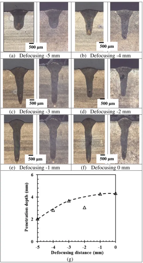
The position of the focal point has an important influence on the welding process and the weld quality. The focal point should be set where the maximum penetration depth is produced [6]. In this work, the effect of defocusing distance on penetration depth was tested on the 5-mm plate at a laser power of 4.0 kW and a welding speed of 4.0 m/min.Fig. 3shows that the maximum penetration depth is ob-tained at defocusing distances from−1 mm (i.e. the focal point is 1 mm below the top surface of the workpiece) to 0 mm (i.e. the focal point is located on the top surface of the workpiece). The focal point has minimum beam size and maximum power density. The placement of the laser beam focus on or below the surface of the workpiece can op-timize the laser beam coupling to the material and thus increase the ir-radiance inside the weld pool, causing the maximum penetration depth [6]. Once the focal point is located into the plate more deeply, the pen-etration depth is reduced. To obtain the maximum penpen-etration depth, all following experiments were conducted at a defocusing distance of −1 mm in this work.
At the optimum defocusing distance, the welding speed was opti-mized to obtain fully penetrated beads by bead-on-plate trials at two laser powers, i.e. 4.2 and 5.2 kW (maximum power available for the fiber laser system used in this work). Then fully-penetrated butt joints were welded at laser powers from 4.2 kW to 5.2 kW and welding speeds from 1.0 m/min to 2.0 m/min (Table 2andFig. 4). At a welding speed lower than 1.0 m/min, the keyhole can become unstable and is easy to collapse, leading to the formation of porosity [6]. In addition, welding defects such as sag and unacceptable undercut can also appear as dem-onstrated in laser welded Cu-Ni alloys at a welding speed below 0.75 m/min using a 4.5 kW Nd:YAG laser [8]. Therefore, the lowest welding speed used in this work is limited to 1.0 m/min. The maximum welding speed is determined by penetration depth. As indicated in
Table 2andFig. 4, the upper limits of the speed are 1.5 or 2.0 m/min
at laser powers of 4.2 and 5.2 kW, respectively for fully-penetrated joints.
All the six fully-penetrated butt joints were examined and evaluated by visual, liquid penetration and radiographic inspection as shown in
Table 2. According to the testing and acceptance standards for the visual, ISO 17637 [11] and DefStan 02-773: Section 8.2, Class 1 [14] and liquid penetration, ISO 3452 [13] and DefStan 02-773: Section 11.3 [14] spec-ifications, all surfaces are to be free from cracks and crack-like defects. For all 6 welds obtained in this study, surface cracks and crack-like de-fects were not found. Surface porosity was only observed in one joint which was welded at 4.7 kW and 1.5 m/min. As indicated inTable 2, the main surface defects are undercut which appeared in all fully-penetrated joints. However, the undercut up to a depth of 1 mm or 10% thickness, whichever is the least, is acceptable according to DefStan 02-773 specification [14]. In this work, the maximum acceptable depth of undercut is 0.5 mm for the 5-mm thick plates. It is found that all 6 butt joints obtained in this work have met the specification requirement of the undercut, i.e.b0.5 mm (Table 2).
Further examination by radiographic testing according to ISO 17636 [12] indicated that all joints have porosity defects but without the pres-ence of visible cracks, as shown inTable 2. According to the DefStan 02-773 (Issue 3, Class 1, Section 13.4) specification [14], cracks and lack of fusion (incomplete root penetration) defects are not acceptable. The uniformly distributed or clustered porosity is not acceptable if it pro-duces a area loss ofN1% [14]. The maximum porosity area allowed in the 150-mm weld length for the 5-mm thick weld is approximately 6 mm2for the Class 1 requirement, i.e. 1.0% porosity [14]. In this work,
the plate butt joints welded at lower laser powers of 4.2 kW and 4.7 kW did not meet the porosity requirements. In contrast, all 3 joints welded at a high laser power of 5.2 kW met the porosity requirements. This is probably due to the better stability of the keyhole at a higher laser power or power density. At lower laser powers (4.2–4.7 kW), the instability of the keyhole can cause its collapse and thus leads to the for-mation of porosity, as demonstrated inFig. 4b-c, where the porosity is located at the lower part of the fusion zone near the root side, indicating that it is most likely formed due to the collapse of the unstable keyhole. In addition, the bubbles can have longer time tofloat and escape from the molten pool at a higher laser power, leading to the decrease in po-rosity. Therefore, autogenousfiber laser welding can be used to obtain satisfactory joints at high laser powers although the internal porosity is still the main welding defects for the 70/30 Cu-Ni alloy.
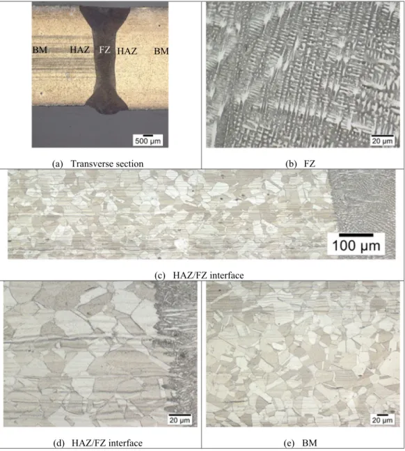
Fig. 5shows transverse section and typical microstructures in the fu-sion zone, HAZ and base metal in Joint-5 welded at a laser power 5.2 kW, a welding speed 1.5 m/min, and a defocusing distance −1 mm. As copper and nickel are completely miscible in both the liquid and solid state (i.e., unlimited solid solubility between Cu and Ni), the Cu-Ni binary phase diagram is isomorphous and thus this alloy can form a single-phase face-centered-cubic alpha phase structure.
In the fusion zone,fine dendritic structure is clearly observed and its growth direction is against the heatflux. The dendritic arms are rich in element Ni and the interdendritic regions are rich in Cu. Thefine den-dritic structure can be quantified by secondary dendritic arm spacing (SDAS). For the Joint-6 welded at a laser power of 5.2 kW and a welding speed of 2.0 m/min, the SDAS around the central fusion zone was mea-sured and found to be approximately 1.62μm (with a standard devia-tion of 0.27μm).
The parent metal displays coarse alpha grain structure but does not reveal any Fe- or Mn-rich intermetallic compounds such as Fe-Ni, al-though they may befinely dispersed in the matric grains of the alloy, as identified by Beccaria et al. [17]. In the HAZ, no grain coarsening was observed.
Fig. 6shows the microhardness profiles at the mid-thickness along the transverse sections of the butt joints. Compared to the base metal, the fusion zone has slightly higher hardness values due to the formation offine dendrites at high cooling rates as usually experienced in laser welding. At a laser power of 4.2 kW, the hardness in the fusion zone
increases slightly from 105 to 109 HV with increasing welding speed from 1.0 to 1.5 m/min. At a laser power of 5.2 kW, the hardness in the fusion zone increases from approximately 102 to 112 HV with increas-ing weldincreas-ing speed from 1.0 to 2.0 m/min. The slightly higher hardness
at a higher welding speed is due to thefiner dendritic structures ob-tained at higher cooling rate. At a given welding speed, the hardness in the fusion zone did not vary significantly with an increasing laser power from 4.2 kW to 5.2 kW. In the present work, the plates are rather
(a) Defocusing -5 mm
(b) Defocusing -4 mm
(c) Defocusing -3 mm
(d) Defocusing -2 mm
(e) Defocusing -1 mm
(f) Defocusing 0 mm
(g)
500 µm
500 µm
500 µm
500 µm
500 µm
500 µm
thick (5 mm) for a 5.2 kWfiber laser and thus the welding process win-dow is relatively narrow. Therefore, it is expected that there is no signif-icant variation in the hardness values of the fusion zone with the laser
power and/or welding speed. Compared to the hardness in the fusion zone, the values in the HAZ slightly decrease from the fusion boundary to the base metal. One abnormal case with increasing hardness values
Table 2
Laser welded butt joints and NDE results.
Joint # Laser power (kW) Welding speed (m/min) Visual [11,14] and liquid penetration [13,14] inspection Radiographic testing [12,14] Joint-1 4.2 1.0 √ (undercut) x (45 porosities; 0.5–1.0 mm) Joint-2 4.2 1.5 √ (undercut) x (60 porosities; 0.5–1.0 mm) Joint-3 4.7 1.5 √ (undercut, porosity) x (32 porosities; 0.5–1.0 mm) Joint-4 5.2 1.0 √ (undercut) √ (13 porosities; 0.5–1.0 mm) Joint-5 5.2 1.5 √ (undercut) √ (10 porosities; b0.5 mm each) Joint-6 5.2 2.0 √ (undercut) √ (8 porosities; b0.5 mm each) Note:√ - Accepted; x – Rejected.
Welding speed 1.0 m/min
Welding speed 1.5 m/min
Welding speed 2.0 m/min
(a) 4.2 kW
(b) 4.2 kW
(c) 4.7 kW
(d) 5.2 kW
(e) 5.2 kW
(f) 5.2 kW
from the fusion boundary to the base metal was observed in the weld obtained at 4.2 kW and 1.5 m/min (Fig. 6b). The parent plate for this joint has also rather high hardness locally. Two more repeated measure-ments for the hardness profile have further confirmed the similar hard-ness distribution in this joint. The abnormal high hardhard-ness values in the parent metal and HAZ are probably due to the non-uniform annealing process of the castings and the presence of some Fe- or Mn-rich inter-metallic compounds [17].
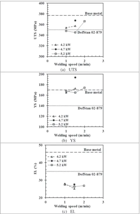
The tensile properties for all the joints and the parent plate are listed inTable 3.Fig. 7indicates the variations of the tensile properties with laser process parameters. The YS for all joints met the minimum re-quirement of 140 MPa defined in the Defence Standard 02-879 for annealed plates [18]. The UTS for the two joints (Joints-4 and 5) welded at 5.2 kW and 1.0–1.5 m/min is slightly lower (2–5 MPa) than the min-imum strength requirement of 350 MPa. It should be emphasized that the two joints met all visual [11,14] and liquid penetration [13,14], as well as radiographic tests [12,14], as indicated inTable 3. The UTS for all other joints met the minimum strength requirement (350 MPa). Overall, the butt joints reach 99–105% of the minimum UTS (350 MPa) as defined in DefStan 02–879 [18]. However, all joints have
lower elongation at fracture than the minimum requirement of 35% for the annealed plates.
Compared to the parent plate, all the welded joints have similar yield strength except for Joint-3 obtained at 4.7 kW and 1.5 m/min, which has a much higher value (194 MPa). Clearly the yield strength is mainly con-trolled by the microstructure. The defects such as undercut, porosity, and sag may influence the load-bearing area and thus slightly reduce or increase the yield strength. The higher yield strength for Joint 3 is probably due to the refined microstructure obtained at low heat input, the lack of undercut defect and sag enhancement at joint root (Fig. 4c). All other tensile properties (UTS, El.) for the welded joints are lower than those for the parent plate, particularly for the ductility, mainly due to the presence of porosity and undercut defects. The joint efficiencies range from 92% to 98% and from 55% to 61%, respectively in terms of the UTS and El. The joint efficiency in terms of UTS (92–98%) obtained in this work is higher than the values of 80–89% for the CO2laser welded 70/30 Cu-Ni alloy by Chakravarthy et al. [7].
In addition, copper has slightly higher absorption of the incident light of the laser with a wavelength of 1.06μm for the solid-state fiber laser as compared to 10.6μm for the CO2laser. Therefore, thefiber laser is
(a) Transverse section
(b) FZ
(c) HAZ/FZ interface
(d) HAZ/FZ interface
(e) BM
FZ
HAZ
HAZ
BM
BM
preferred for the welding of cupronickel alloys compared to the CO2
laser.
In spite of slight hardening after laser welding, all tensile specimens of the plate butt joints failed in the fusion zone (FZ) and/or at the FZ/
HAZ interfaces due to the presence of porosity and undercut (Table 3
andFig. 8).
All of the bend testing specimens passed the 180° bend requirement as outlined in ISO 15614-6 [10] by achieving the required deformation
Welding speed 1.0 m/min
Welding speed 1.5 m/min
Welding speed 2.0 m/min
(a) 4.2 kW
(b) 4.2 kW
(c) 4.7 kW
(d) 5.2 kW
(e) 5.2 kW
(f) 5.2 kW
Fig. 6. Hardness profiles along the mid-thicknesses across the welded butt joints.
Table 3
Tensile properties in the annealed or as-welded conditions.
YS (MPa) UTS (MPa) El. (%) JE (% in UTS) JE (% in El.) Failure locations Annealed plates: DefStan 02–879: Part 1, Issue 1, Annex B 140 350 35
Parent plates (annealed) tested in this work 170 377 46
Joint-1 165 354 28 94 61 3 at FZ/HAZ Joint-2 173 357 25 95 55 3 in FZ Joint-3 194 368 28 98 60 3 at FZ/HAZ Joint-4 168 348 28 92 60 3 in FZ Joint-5 165 345 26 92 58 1 in FZ + 2 at FZ/HAZ Joint-6 174 366 27 97 58 1 in FZ + 2 at FZ/HAZ
(a) UTS
(b) YS
(c) El.
Fig. 7. Tensile properties of the butt joints as functions of laser power and welding speed.
A failed tensile specimen for Joint-6
A failed tensile specimen for Joint-6
A failed tensile specimen for a parent plate
A failed tensile specimen for a parent plate
without the formation of cracks (Table 4). While some specimens devel-oped small (b3 mm) cracks at the corner of the specimens, which is ac-ceptable by the testing standard, there was no correlation between the formation of these cracks and the orientation of the specimens or the welding procedures. The results of the bend testing imply that all laser welds had good ductility in both the weld metal and HAZs, and that the defects such as undercut, porosity, and sag present in the joints were not detrimental to the performance of the welds.
4. Conclusions
• Autogenous high power fiber laser welding can be used to obtain 70/ 30 Cu-Ni alloy joints with all defects well within the specification re-quirements.
• In spite of the lack of intergranular welding cracking in the weld and HAZ in thefiber laser welded 70/30 Cu-Ni alloy, porosity is observed to be the major defects present in the butt joints without the use of filler metal.
• Compared to the coarse grains in the parent plate, the fusion zone in laser welded joints displaysfine dendritic structures, causing slight hardening in the fusion zone compared to the annealed base metal. • No grain coarsening is observed in the HAZ.
• Compared to the parent plate, all welded joints have similar or higher yield strength but the UTS and elongation are degraded, particularly for the ductility, mainly due to the presence of porosity and undercut. Nearly all butt joints met the minimum yield and ultimate tensile strength requirements, but not for the ductility according to the De-fence Standard 02–879 [18].
• The joint efficiencies range from 92% to 98% and from 55% to 61%, re-spectively, in terms of the UTS and elongation. The higher joint strength efficiencies (92–98%) than the values of 80–89% reported using a CO2laser by Chakravarthy et al. [7] indicate thefiber laser
with higher energy absorptivity is preferred for the welding of cupro-nickel alloys, compared to the CO2laser.
• All of the welding procedures met the requirements for the 180° guided bend tests in both the root bend and face bend configurations.
CRediT authorship contribution statement
X. Cao: Conceptualization, Methodology, Investigation, Data curation, Formal analysis, Project administration, Writing - original draft. A. Nolting: Data curation, Writing - review & editing.
Acknowledgements
The authors are grateful to technical staff E. Poirier for laser welding experiments, X. Pelletier for metallographic preparation, microscopic examination and hardness testing, D. O'Keefe for the machining of the samples, M. Guérin for the tensile testing and determination of the ten-sile properties, Dr. J. Gholipour (team leader) and Dr. J. Huang from Canada's Department of National Defence.
References
[1] M. Prager, Jr E.W. Thiele, Welding copper-nickel ships, Welding J. (May 1977) 15–23.
[2] K. Lahti, J. Lukkari,“Welding of Copper-Nickel Alloys at Kvaerner Masa-Yards”, Svetsaren, No. 2, 2002 9–10.
[3] P. Ferro, F. Bonollo, A. Tiziani, Laser welding of copper-nickel alloys: a numerical and experimental analysis, Science & Technology of Welding & Joining 10 (3) (2005) 299–310.
[4] J.H. Devletian, M.J. Sullivan, Flux Cored Arc Welding of CuNi 90/10 Piping with CuNi 70/30 Filler Metal, https://www.nsrp.org/wp-content/uploads/2015/09/Deliver-able-All_Position_Flux_Cored_Electrode_Final_Report-Portland_State_University. pdf2006.
[5] Copper Development Association, Copper-Nickel Welding and Fabrication, Copper Development Association Inc. Publication A7020-99/13, Revised in February 2013 2nd edition Nickel Institute Publication 12014, February 2013.
[6] X. Cao, W. Wallace, C. Poon, J.-P. Immarigeon, Research and Progress in laser welding of wrought aluminum alloys. I. Laser welding processes, Mater. Manuf. Pro-cess. 18 (1) (2003) 1–22.
[7] M.P. Chakravarthy, N. Ramanaiah, B.S.K. Sundara Siva Rao, Effect of laser welding on mechanical properties of 70/30 cu-Ni alloy welds, Proc IMechE Part B: J. Engineering Manufacture 228 (9) (2014) 1153–1161.
[8] E.W. Reutzel, L. Kern, J.F. Tressler, J. Avalos, Laser-GMA hybrid pipe welding system, Final Technical Report, Center for Naval Shipbuilding Technology, 2007 , Nov. [9] Defence Standard (DefStan) 02-780 (NES 780),“Requirements for 70/30 Copper
Nickel Alloy Material”, Part 3, Issue 1 – Class 6–280, Ministry of Defence, the United Kingdom, 1998 August.
[10] ISO 15614-6, Specification and Qualification of Welding Procedures for Metallic Ma-terials– Welding Procedure Test – Part 6: Arc and Gas Welding of Copper and its Al-loys, 2006.
[11]ISO 17637, Non-Destructive Testing of Welds– Visual Testing of Fusion-Welded Joints, 2016.
[12] ISO 17636-1: 2013(E), Non-Destructive Testing of Welds– Radiographic Testing – Part 1: X-Ray and Gamma-Ray Techniques with Film, 2013.
[13]ISO 3452: 2013(E), Non-Destructive Testing– Penetrant Testing – Part 1: General Principles, 2013.
[14]Defence Standard (DefStan) 02-773, Minimum Non-Destructive Examination Ac-ceptance Standards for Welds in HM Submarines and Surface Ships Not in Class, Ministry of Defence, the United Kingdom, June 2013.
[15]ISO 4136: 2012(E), Destructive Tests on Welds in Metallic Materials– Transverse Tensile Test, 2012.
[16] ASTM Standard E190-92, Standard Test Method for Guided Bend Test of Ductility of Welds, vol. Volume 3.01, ASTM International, 2011.
[17]A.M. Beccaria, G. Poggi, Y.Z. Wang, Effect of heat treatments on Cu-Ni 70/30 alloy pitting susceptibility in sea water at different temperatures, Werkst. Korros. 45 (1994) 562–569.
[18]Defence Standard (DefStan) 02-879, Requirements for Copper Alloy Materials in HM Submarines and Surface Ships Not in Class, Part 1: Sheet, Strip and Plate, Min-istry of Defence, the United Kingdom, 2011 January.
Table 4
180° bend testing results in as-welded conditions.
Specimen geometries Orientation FlawsN 3 mm Joint-1 Flat Root bend, face bend None Joint-2 Flat Root bend, face benda
None Joint-4 Flat Root bend, face bend None Joint-5 Flat Root bend, face bend None Joint-6 Flat Root bend, face bend None a
![Fig. 1. Test pieces for butt joints in plates [10].](https://thumb-eu.123doks.com/thumbv2/123doknet/14009717.456451/4.892.157.753.81.473/fig-test-pieces-butt-joints-plates.webp)