Publisher’s version / Version de l'éditeur:
Vous avez des questions? Nous pouvons vous aider. Pour communiquer directement avec un auteur, consultez la première page de la revue dans laquelle son article a été publié afin de trouver ses coordonnées. Si vous n’arrivez pas à les repérer, communiquez avec nous à [email protected].
Questions? Contact the NRC Publications Archive team at
[email protected]. If you wish to email the authors directly, please see the first page of the publication for their contact information.
https://publications-cnrc.canada.ca/fra/droits
L’accès à ce site Web et l’utilisation de son contenu sont assujettis aux conditions présentées dans le site LISEZ CES CONDITIONS ATTENTIVEMENT AVANT D’UTILISER CE SITE WEB.
13th National Conference Caius Iacob in Fluid Mechanics and Technological
Applications, INCAS [Proceedings], 2011
READ THESE TERMS AND CONDITIONS CAREFULLY BEFORE USING THIS WEBSITE.
https://nrc-publications.canada.ca/eng/copyright
NRC Publications Archive Record / Notice des Archives des publications du CNRC :
https://nrc-publications.canada.ca/eng/view/object/?id=79e67f93-1c79-4e10-b20d-3c4eb3348ef6
https://publications-cnrc.canada.ca/fra/voir/objet/?id=79e67f93-1c79-4e10-b20d-3c4eb3348ef6
NRC Publications Archive
Archives des publications du CNRC
This publication could be one of several versions: author’s original, accepted manuscript or the publisher’s version. / La version de cette publication peut être l’une des suivantes : la version prépublication de l’auteur, la version acceptée du manuscrit ou la version de l’éditeur.
Access and use of this website and the material on it are subject to the Terms and Conditions set forth at
Smart concepts for actuation system and its control in a morphing
wing
Grigorie, Teodor lucian; Popov, Andrei Vladimir; Botez, Ruxandra Mihaela;
Mamou, Mahmoud; Mébarki, Youssef
Smart concepts for actuation system and its control in a morphing wing
Teodor Lucian Grigorie, Andrei Vladimir Popov and Ruxandra Mihaela Botez
École de Technologie Supérieure, Montréal, Québec H3C 1K3, Canada
Mahmoud Mamou and Youssef Mébarki
National Research Council, Ottawa, Ontario K1A 0R6, Canada
Abstract
The objective of this research work is the development of an actuation control concept for a new morphing wing mechanism using smart materials made of Shape Memory Alloy (SMA) for the actuators and surface mounted pressure sensors. These actuators modify the upper wing surface, made of a flexible skin, so that the laminar-to-turbulent transition point moves close to the wing airfoil trailing edge. An intelligent controller was used for the open loop development step of the morphing wing project, and the closed loop of the morphing wing system included, as an internal loop, the controller actuation lines, based on the pressure information received from the sensors and on the transition point position estimation. The strong nonlinearities of the SMA actuators’ characteristics and the system requirements led to the choice of a Fuzzy Logic Controller. The input-output mapping of the fuzzy model was designed taking account of the system’s error and change in error. After preliminary numerical simulations using to tune the controller, an experimental validation was performed. The experimental validation consisted in experimental bench tests in laboratory conditions in the absence of aerodynamic forces, and in wind tunnel tests; the transition point real time position detection and visualization were realized.
1. Introduction
The recent aims in aviation bring in front new horizons for researches related to the drag reduction through morphing an adaptive wing, which is motivated by rising fuel costs and environmental concerns. The concept relies on delaying the transition location toward the wing trailing edge by morphing the upper surface of the wing. The main objective of this concept is to promote large laminar regions on the wing surface, thus reducing drag over an operating range of flow conditions characterized by Mach numbers, airspeeds, and incidence angles [1]-[3]. The airborne modification of an aircraft wing airfoil shape can be realized continuously to maintain laminar flow over the wing surface as flight conditions change. To achieve such a full operating concept, a closed loop control system has to be developed to link the flow fluctuations over the wing surface to the morphing mechanism (actuators). The flow fluctuation signals can be detected by conventional pressure transducers or the new emerging pressure optical sensors. Linked to a controller system, the collected data would be treated in real time aiming to identify the location of transition and then sending a signal to the actuator system to adjust the wind surface to delay the transition location.
The here presented work was performed under the 7.1 Consortium for Research and Innovation in Aerospace in Quebec (CRIAQ) collaborative project between academia and industries. In this project, the laminar flow behavior past aerodynamically morphing wing was improved to obtain significant drag reductions. The project partners were the École de Technologie Supérieure (ETS), École Polytechnique of Montreal, the Institute for Aerospace Research at the National Research Council Canada (IAR-NRC), Bombardier Aerospace, and Thales Avionics. This collaboration calls for both aerodynamic modeling as well as conceptual demonstration of the morphing principle on real models placed in the wind tunnel.
2. Project context
A first phase of this project involved the determination of some optimized airfoils available for 35 different flow conditions expressed in terms of five Mach numbers (0.2, 0.225, 0.25, 0.275, 0.3) and seven angles of attack (-1˚, -0.5˚, 0˚, 0.5˚, 1˚, 1.5˚, 2˚) combinations. The optimized airfoils, derived from a laminar WTEA-TE1 reference airfoil [4], [5], were calculated by the Ecole Polytechnique team ([6]), and were used as a starting point in the actuation system design. Three steps were completed in the actuation system design phase: optimization of the number and positions of flexible skin actuation points, establishment of each actuation line’s architecture, and the analytical modeling of the smart materials actuators used in this application. The next phase of the project was related to the design of the actuation control. In this design, numerical simulations of the open loop morphing wing integrated system, based on a SMA non-linear analytical model ([7]-[8]), were used first. As subsequent validation methods, a bench test and a wind tunnel test were performed ([9]-[10]). Simultaneously, the transition point real time position detection and visualization were realized. Finally, the design and the experimental validation in wind tunnel tests were performed for the morphing wing closed loop system ([11]-[12]).
The chosen wing model was rectangular with a chord of 0.5 m and a span of 0.9 m; the model was equipped with a flexible skin made of composite materials morphed by two actuation lines (Fig. 1). The flexible skin was manufactured in
a 4 ply laminate structure in a polymer matrix, with two unidirectional carbon fiber inner plies and two hybrid Kevlar®/carbon fiber outer plies. The hybrid Kevlar®/carbon fiber was used in the chordwise direction, in which flexibility was needed for profile modification, whereas the low-modulus unidirectional carbon fiber was spanwise installed, in which case rigidity was preferred. The total thickness of the skin was 1.3 mm, the total Young modulus was 60 GPa, Poisson’s ratios were 0.12 for carbon/Kevlar® hybrid and 0.25 for unidirectional carbon [13]-[17]. Each actuation line uses shape memory alloys SMA wires as actuators. At the same time, 32 pressure sensors (16 optical and 16 Kulite), distributed on the flexible skin chord-wise and span-wise, were installed on the wing’s flexible skin. These sensors were positioned on two diagonal lines at an angle of 15 degrees from its centerline. The rigid lower structure was made from aluminum, and was designed to allow space for the actuation system and its wiring.
Fig. 1 Mechanical schematic of the morphing wing model
The shape memory actuator wires used here were made of nickel - titanium, and contract as muscles do when electrically driven. This ability to flex or shorten is a characteristic of certain alloys that dynamically change their internal structure at a certain temperature. These alloys have the properties of exhibiting martensitic transformation when they deform at a low temperature phase, and may recover their original shape after heating [11]. This property of changing the wire length as a function of the electrical current passing through the wire is used for actuation purposes [11]. Another major reason for the use of Nitinol and Ni-Ti material is that Nitinol is the most effective material at withstanding repeated cycles of heating and cooling without exhibiting a fatigue phenomenon [18].
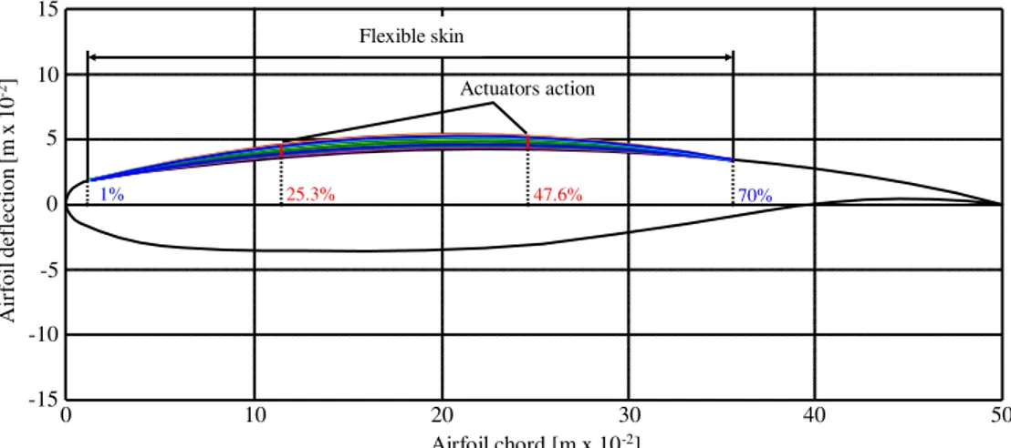
Each of our actuation lines uses three SMA wires (1.8 m in length) as actuators, and contains a cam, which moves in translation relative to the structure (on the x-axis in Fig. 1). The cam causes the rod movement to be related on the roller and on the skin (on the z-axis). A compression gas spring was also used as recall. When the SMA is heated the actuator contracts and the cam moves to the right, resulting in the rise of the roller and the displacement of the skin upwards. Cooling of the SMA, results in a cam motion to the left, and thus a movement of the skin downwards. The horizontal displacement of each actuator is converted into a vertical displacement at a rate of 3:1, which gives the conversion of the horizontal stroke of x mm into a vertical stroke z = x/3. The cam factor cf = 1/3. From the optimized airfoils, an approximately 8 mm maximum vertical displacement was obtained for the rods (Fig. 2), which thus required a maximum horizontal displacement of 24 mm from the actuators.
Fig. 2 Morphed airfoil for different flow cases
To control the transition point position through morphing of the airfoil shape the control of the actuation system should be performed. In this way two electrical power supplies were used. The role of power supply command is given by a controller, which receives information about the external airflow state from a set of several pressure sensors. The controller compares the information received from sensors with the information stored in a database in the computer memory. If the controller executes the command from the information stored in the database, then the control strategy is defined as open loop (Fig. 3), because of the fact that the controller gives no feedback about the airflow state. If the controller receives
Gas spring Roller First actuating line SMA actuator Rod Cam Flexible skin (airfoil upper surface)
Airfoil leading edge
Airfoil trailing edge
Airfoil lower surface
x z Second actuating line 1% 25.3% 47.6% 70% Actuators action Airfoil chord [m x 10-2] Air foil de flec ti on [m x 10 -2] 0 10 20 30 40 50 -15 -10 -5 0 5 10 15 Flexible skin
information from the sensors about the airflow state and compares it with the information stored in the database, then decisions can be made and actuators states can be adjusted and we further define the control strategy as closed loop (Fig. 4). So, depending on the project evolution phase, two architectures were considered for our morphing system: open loop and closed loop. The difference between these two architectures is given by the use of the transition point as feedback signal.
Fig. 3 Open loop control system schematics
Fig. 4 Closed loop control system schematics
3. Actuation system controller design
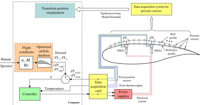
The architecture of the developed open loop morphing wing model can be observed in Fig. 5 (starting from general model in Fig. 3). As we can observe, the controller purpose is to control the SMA actuators by the instrumentality of the power supplies in order to morph the upper surface of the wing until the real vertical displacements (dY1real,dY2real) in the two actuation points equal the desired vertical displacements (dY1opt,dY2opt) corresponding to the optimized profile,
theoretically obtained for the current flight condition. Taking into account that the output of the data acquisition card, controlling the power supplies, are in a direct-proportionality with the electrical currents applied to the actuators, in the design stage and in the numerical simulations, the controller output will be considered the electrical current. The scheme in Fig. 5 shows that, for security reasons, some thermocouples were used to monitor the actuators temperatures; the used actuators are six wires of Ni-Ti (three for each of the two actuation lines) which work at temperatures over 60-70 oC.
Fig. 5 Architecture of the developed open loop morphing wing model
Variable airfoil shape CFD database Variable flow conditions , V, Re Optical sensors Loop controller SMA actuators Variable airfoil shape CFD database Transition point Variable flow conditions , V, Re Optical sensors Loop controller SMA actuators Controller e , M, Re Human Operator Flight conditions Optimised airfoils database Computer Desired dY1, dY2 (dY1opt, dY2opt) dY1 dY2 SMA1 SMA2
...
From position sensors dY1real, dY2real Data acquisition card Power supplies Temperatures Reference profile Real profile From thermocouples Electrical current Pressure sensors Signal processing Matlab/SimulinkData acquisition system for pressure sensors
Transition position visualization
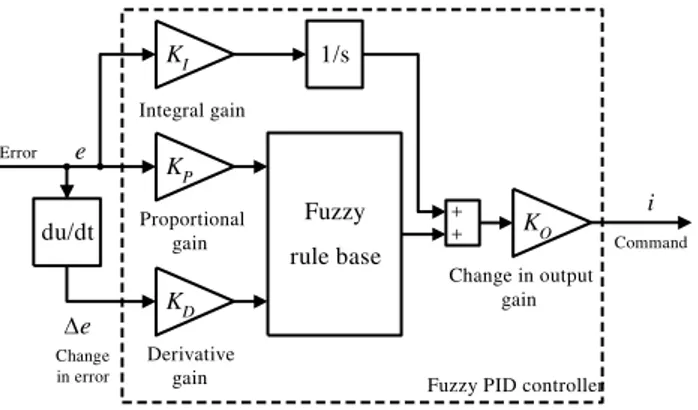
For the actuation lines controller different architectures were developed: by using classical PID architecture, and fuzzy logic based - PIDs with constant coefficients or in self-tuning variant. Here presented controller is a fuzzy PID with constant proportional, derivative and integral coefficients. As inputs of the controller were used the error e (the difference between the desired and the real vertical deflections) and the derivative of the error, very well known in the fuzzy control theory as change in error e, while as output was considered the electrical current i provided to the actuators (Fig. 6). The architecture was used for both actuation channels of the morphing model. The elements in Fig. 6 are: KI- integral gain,
P
K - proportional gain, KD- derivative gain, and KO- change in output gain (which includes the conversion from output
voltage of the data acquisition card to electrical current obtained at the output of the power supply).
Fig. 6 Fuzzy PID controller architecture
Each of the fuzzy logic controller (FLC) input or output signals have the real line as the universe of discourse [19]-[20]. For our system, the [-1, 1] interval was chosen as the universe for inputs signals, and [0, 1] interval was chosen as the universe for output signal. Also, following numerical simulations, we have chosen a number of two membership functions for the first input, three membership functions for the second input, and three membership functions for the output. The shapes chosen for inputs membership functions were s-function, π-function, respectively z-function. Generally, an s-function shaped membership function can be implemented using a cosine function:
, if , 1 if , cos 1 2 1 if , 0 ) , , ( right right left left right right left right left x x x x x x x x x x x x x x s (1)
a z-function shaped membership function is a reflection of a shaped s-function:
, if , 0 if , cos 1 2 1 if , 1 ) , , ( right right left left right left left right left x x x x x x x x x x x x x x z (2)
and a π -function shaped membership function is a combination of both functions: )], , , ( ), , , ( min[ ) , , , ,
(xleft xm1 xm2 xright x s xleft1 xm1 x z xm2 xright x
(3)
with the peak flat over the [xm1,xm2] middle interval. x is the independent variable on the universe, xleft is the left
breakpoint, and xright is the right breakpoint [19].
To define the rules, a zero-order Sugeno fuzzy model was chosen, which for a two input - single output system with N rules is given by:
. ) , ( then , is and is If : Rule , ) , ( then , is and is If : Rule , ) , ( then , is and is If : 1 Rule 0 2 1 2 2 1 1 0 2 1 2 2 1 1 1 0 2 1 1 1 2 2 1 1 1 N N N N i i i i b x x y A x A x N b x x y A x A x i b x x y A x A x (4) ) , 1 (i N Ai
q are associated individual antecedent fuzzy sets of each input variable, xq(q1,2) are individual input
variables, and yi(i1,N) is the first-order polynomial function in the consequent, and ( 1, )
0 i N
bi denotes a scalar offset.
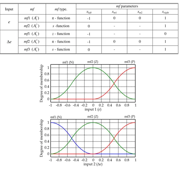
According to the values in the Table 1, the membership functions for the inputs are by the form depicted in Fig. 7, Fuzzy rule base KP Proportional gain e KD Derivative gain Error 1/s i Command
Fuzzy PID controller
KI Integral gain KO Change in output gain + + du/dt e Change in error
and are given by the eq. (1), (2) or (3): ), , 1 , 0 , 0 , 1 ( ) ( ) ( 2 2 1 1 x A x x A (5) ), , 0 , 1 ( ) ( 1 2 x z x A (6) ). , 1 , 0 ( ) ( ) ( 3 2 2 1 x A x s x A (7)
Table 1. Parameters of the input’s membership functions
Input mf mf type. mf parameters
xleft xm1 xm2 xright e mf1 ( ) 1 1 A π - function -1 0 0 1 mf2 ( 2) 1 A s -function 0 - - 1 e mf1 ( 1) 2 A z - function -1 - - 0 mf2 ( 2) 2 A π - function -1 0 0 1 mf3 ( 3) 2 A s - function 0 - - 1
Fig. 7 Membership functions for the fuzzy logic controller inputs
For the output membership functions three constant values were chosen: 0, 0.5 and 1. Starting from the inputs’ and output’s membership functions, a set of 6 inference rules were obtained (N=6):
. 1 ) , ( then , is and is If : 6 Rule , 5 . 0 ) , ( then , is and is If : 5 Rule , 0 ) , ( then , is and is If : 4 Rule , 5 . 0 ) , ( then , is and is If : 3 Rule , 0 ) , ( then , is and is If : 2 Rule , 0 ) , ( then , is and is If : 1 Rule 6 3 2 2 1 5 2 2 2 1 4 1 2 2 1 3 3 2 1 1 2 2 2 1 1 1 1 2 1 1 e e y A e A e e e y A e A e e e y A e A e e e y A e A e e e y A e A e e e y A e A e (8)
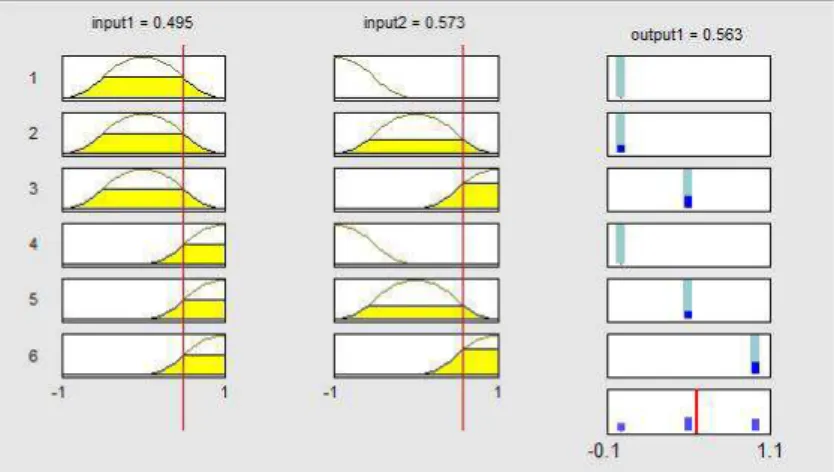
The rule-based inference chosen for each consequent is presented in Fig. 8. With the previous considerations, the fuzzy control surface results by the form presented in Fig. 9.
The fuzzy control surface was chosen in this way because it is normal that in the SMA cooling phase the actuators would not be powered. Therefore, the fuzzy controller was chosen to work in tandem with a bi-positional controller (particularly an on-off one); the controller should behave as a switch between the SMA cooling and heating phases, in which the output current is 0 A, or is controlled by the fuzzy logic controller. As a consequence, the resulted controller operational scheme resulted by the form in Fig. 10.
To optimize all coefficients in the control scheme, the open loop of the morphing wing system was implemented in Matlab-Simulink model as in Fig. 11.
input 2 (e) Deg ree of m embe rsh ip 0 0.2 0.4 0.6 0.8 1 mf1 (N) mf2 (Z) mf3 (P) -1 -0.8 -0.6 -0.4 -0.2 0 0.2 0.4 0.6 0.8 1 input 1 (e) Deg ree of m embe rsh ip 0 0.2 0.4 0.6 0.8 1 mf1 (N) mf2 (Z) mf3 (P) -1 -0.8 -0.6 -0.4 -0.2 0 0.2 0.4 0.6 0.8 1
Fig. 8 Rule-based inference for the fuzzy logic controller
Fig. 9 The fuzzy control surface
Fig. 10 Operational scheme of the controller
Fig. 11 Simulation model of the open loop morphing wing system with fuzzy controller
KP Proportional gain e KD e Derivative gain 1/s KI Integral gain KO Change in output gain e - Membership Functions
e - Membership Functions
Fuzzification Inference Defuzzification s Z P N Z P e /e + + + -i Command e > 0 Desired Deflection superior to Actual Deflection ? Error i=0 for heating phase NO YES i=0 for cooling phase SMA actuator Real deflection Desired deflection e
Actuation lines controller
Temperature [K] skin deflection [mm] skin deflection [mm] desired deflection [mm] SMA elongation [m] skin deflection [mm] 0 skin deflexion [mm] 1 1 3 desired deflection [mm] 3/1000 cam factor mm to m XY Graph Scope 0.078 SMA max set
[m] 0 SMA elongation [m] Current Force Displacement Temperature SMA Model 1.8 SMA Initial length [m] 1.8 SMA Initial length Memory2 Memory1 F aero [N] x [m] F SMA [N] y [mm] Mechanical system Diff error Temperature Current out Actuation lines controller
0 Current [A] 273.15 Celsius to Kelvin 1000 Aerodynamic force [N]
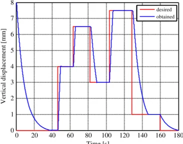
After a tuning operation the optimum values of the controller gains were established. Further, the controller was tested through numerical simulation to ensure that it works well. A relevant test was for a successive steps signal applied to the input of the controlled actuator; the obtained characteristics are shown in Fig. 12. The results confirm that the obtained controller works very well in both phases (heating and cooling) of the SMA actuators.
Fig. 12 Numerical simulation results for the actuation line controller
4. Wind tunnel validation of the designed controller
The wind tunnel tests were performed in the IAR-NRC wind tunnel at Ottawa. During the project were made different wind tunnel tests in order to validate the interaction between the components of physical model of the morphing wing (Fig. 13). The last two tests were decisive for the open loop, respectively for the closed loop architectures validation.
Fig. 13 Wind tunnel morphing wing model
Based on the theoretical and numerical simulation results analysis, two Programmable Switching Power Supplies AMREL SPS100-33, controlled by Matlab/Simulink through a Quanser Q8 data acquisition card, were used to implement the controller physical model [21]-[23]. The power supplies have RS-232 and GPIB IEEE-488 as standard features and technical characteristics that include: Power 3.3kW, Voltage (dc) 0-100 V, Current (dc) 0-33 A. The Q8 data acquisition card has 8 single-ended analog inputs with 14-bit resolution. All 8 channels can be sampled simultaneously at 100 kHz, with an A/D conversion times of 2.4 µs/channel. Simultaneous sampling and sampling frequencies of up to 350 kHz for two channels can be performed. Also, the Q8 card is equipped with 8 analog outputs, software programmable voltage ranges and simultaneous update capability with an 8 µs settling time over the full scale (20V).
The acquisition board was connected to a PC and programmed via Matlab/Simulink R2006b and WinCon 5.2 (Fig. 14). The input were two signals from the Linear Variable Differential Transformer (LVDT) potentiometers, which indicate the positions of the SMA actuators, and six signals from thermocouples installed on each of the SMA wires’ components. The acquisition sampling time was set to 10 µs. The output channels of the acquisition board were used to control each power supply through analog/external control by means of a DB-15 I/O connector.
In the open loop wind tunnel tests, simultaneously with the controller validation, the real-time detection of the transition point and visualization were performed, for all the 35 optimized airfoils. Also, a comparative study was realized based on the transition point position for the reference airfoil and for each optimized airfoil, with the aim to validate the aerodynamic part of the project. All tests confirmed the well work of the designed controller.
0 20 40 60 80 100 120 140 160 180 desired obtained 0 1 2 3 4 5 6 7 8 Verti ca l displa ce me nt [mm ] Time [s]
Fig. 14 Matlab/Simulink actuators control
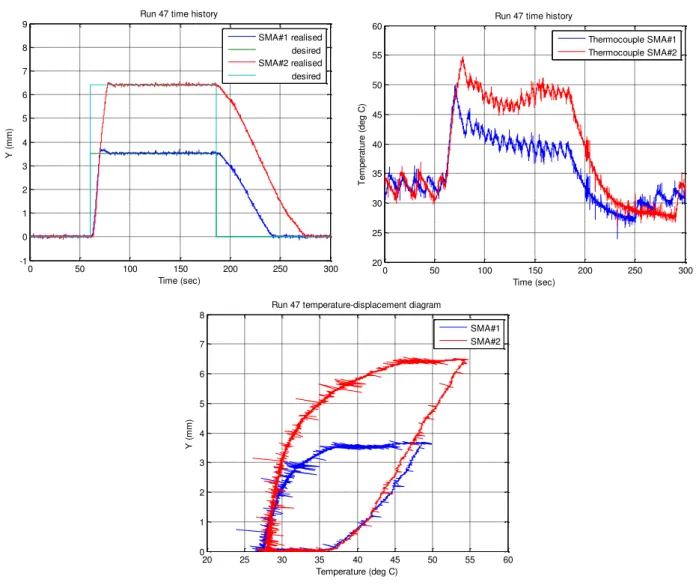
In Fig. 15 are shown the results obtained for the run test 47 (airfoil case C124, Mach = 0.275, alpha = 0 degree). From figure can be observed that the controller work even the actuator required displacement is zero because of the gas springs pretension forces.
Fig. 15 Wind tunnel results for airfoil case C124: Mach = 0.275, alpha = 0 degree
The transition detection was performed in real time using the pressure data signals obtained from the Kulite pressure sensors. The pressure data were acquired using the IAR-NRC analog data acquisition system, which was connected to the sensors. The sampling rate of each channel was at 15 kHz, which allowed a pressure fluctuation FFT spectral decomposition of up to 7.5 kHz for all channels. The signals were processed in real time using Simulink. The pressure signals were analyzed using Fast Fourier Transforms (FFT) decomposition to detect the magnitude of the noise in
0 Volts Temp StartVolt termocouple1 termocouple2 termocouple3 position 2 temp amps control V start 5V SMA2 termocouple1 termocouple2 termocouple3 position 1 temp amps control V start 5V SMA1 Q8 Quanser Analog Output Q8 Quanser Analog Input Amps Analog Input Analog Output 0 0 50 100 150 200 250 300 -1 0 1 2 3 4 5 6 7 8 9 Time (sec) Y ( m m )
Run 47 time history
SMA#1 realised desired SMA#2 realised desired 0 50 100 150 200 250 300 20 25 30 35 40 45 50 55 60 Time (sec) Te m p e ra tu re ( d e g C )
Run 47 time history
Thermocouple SMA#1 Thermocouple SMA#2 20 25 30 35 40 45 50 55 60 0 1 2 3 4 5 6 7 8 Temperature (deg C) Y ( m m )
Run 47 temperature-displacement diagram
SMA#1 SMA#2
the surface air flow. Subsequently, the data was filtered by means of high-pass filters and processed by calculating the Root Mean Square (RMS) of the signal to obtain a plot diagram of the pressure fluctuations in the flow boundary layer. This signal processing is necessary to disparate the inherent electronically induced noise, by the Tollmien-Schlichting waves that are responsible for triggering the transition from laminar to turbulent flow. The measurements showed that in the processed data, the transition appeared at frequencies between 3÷5kHz and the magnitude of the pressure variations in the laminar flow boundary layer are on the order of 5e-4 Pa. The transition from the laminar flow to turbulent flow was shown by an increase in the pressure fluctuation, which was indicated by a drastic variation of the pressure signal RMS.
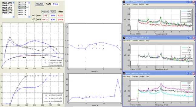
The following figures (Fig. 16 and Fig. 17) show the instant plots of the Cp’s, RMS’s and spectre for the 15 pressure signals channels for airfoil case C124 with un-morphed and morphed profile. The sensors # 11 and # 12 were removed from plots due to the bad dynamic signals which show electrical failure of the sensors. Sensor # 5 show a misalignment of the Cp value with its neighbours which means there is a leak or a pinched reference tube. The dynamic signal of the sensor # 5 was good and for that reason the sensor value was kept on the plots.
Fig. 16 Instant plots of the Cp’s, RMS’s and spectre for airfoil case C124 un-morphed
Fig. 17 Instant plots of the Cp’s, RMS’s and spectre for airfoil case C124 morphed
Left middle figure shows the Xfoil Cp’s values for the reference airfoil (black line and circles) and for the optimised airfoil (blue line and circles). Bottom figure shows the normalized RMS for 15 sensors for the reference un-morphed airfoil and optimised airfoil. Right figures show the FFT spectra for the 15 channels. It is observed that for the sensor #5, its Cp is not aligned with the Cp’s of the other sensors, which is explained by its leak or a pinched reference tube. In Fig. 16 (un-morphed profile) the transition is localized by the sensor # 8 maximum RMS and the highest noise band on the spectral plots (CH 3 black spectra on the right middle plot), while in Fig. 17 (morphed profile) the transition is localized
by the sensor # 14 maximum RMS and the highest noise band on the spectral plots (CH 2 magenta spectra on the right lower plot).
5. Conclusions
The approaches for the design and for the validation of a smart concept for the actuation system control in a morphing wing were presented. Also, the developed morphing mechanism used smart materials such as Shape Memory Alloy (SMA) in the actuation mechanism. The controller was designed to control the SMA actuators by means of the electrical current supply, in order to cancel the deviation between the required values for vertical displacements (corresponding to the optimized airfoils) and the real values, obtained from two position transducers.
From the experimental results, it can be observed that a high frequency noise parasites the LVDT sensors and thermocouple’s instrumentation amplifiers, but with small amplitudes, which does not significantly influence the flow transition point position. All the numerical simulated and experimentally tested situations results confirmed that the designed controller works very well.
Acknowledgments
We would like to thank the Consortium of Research in the Aerospatial Industry in Quebec (CRIAQ), Thales Avionics, Bombardier Aerospace, and the National Sciences and Engineering Research Council (NSERC) for the support that made this research possible. We would also like to thank George Henri Simon for initiating the CRIAQ 7.1 project, and Philippe Molaret from Thales Avionics and Eric Laurendeau from Bombardier Aeronautics for their collaboration on this work.
References
1. Jacob, J. D., On the Fluid Dynamics of Adaptive Airfoils, Proceedings of 1998 ASME International Mechanical Engineering Congress and Exposition, American Society of Mechanical Engineers, Fairfield, NJ, 15–20 Nov. 1998, pp. 1–10.
2. Driver, J., and Zingg, D. W., Optimized Natural-Laminar-Flow Airfoils, 44th AIAA Aerospace Sciences Meeting and Exhibit, AIAA, Reston, VA, 9– 12 Jan. 2006, pp. 1–16; also AIAA Paper 2006-247, 2006.
3. Zingg, D.W., Diosady, L., and Billing, L., Adaptive Airfoils for Drag Reduction at Transonic Speeds, 24th Applied Aerodynamics Conference, AIAA, Reston, VA, 5–8 June 2006, pp. 1–15; also AIAA Paper 2006-3656, 2006.
4. Khalid, M., Jones, D.J., Navier Stokes Investigation of Blunt Trailing Edge Airfoils using O-Grids, AIAA Journal of Aircraft, vol.30, no.5, 1993, pp. 797-800
5. Khalid, M., Jones, D.J., A CFD Investigation of the Blunt Trailing Edge Airfoils in Transonic Flow, Inaugural Conference of the CFD Society of Canada, June, 1993.
6. Sainmont, C., Paraschivoiu, I. and Coutu, D., Multidisciplinary Approach for the Optimization of a Laminar Airfoil Equipped with a Morphing Upper
Surface, NATO AVT-168 Symposium on "Morphing Vehicle", Evora, Portugal, 2009.
7. Grigorie, L.T., Botez, R.M., New adaptive controller method for SMA hysteresis modeling of a morphing wing, The Aeronautical Journal, Vol.114(1151), pp. 1-13, 2009.
8. Grigorie, L.T., Botez, R.M., Adaptive neuro-fuzzy inference system based controllers for Smart Material Actuator modeling, Journal of Aerospace Engineering, Vol. 223(G6), pp. 655-668, 2009.
9. Popov, A.V., Botez, R. M., Mamou, M. and Grigorie, T.L., Optical sensor pressure measurements variations with temperature in wind tunnel testing, AIAA Journal of Aircraft, Vol. 46 (4), pp. 1314-1318, 2009.
10. Popov, A.V., Grigorie, T. L., Botez, R.M., Mamou, M., Mebarki, Y., Real Time Morphing Wing Optimization Validation Using Wind-Tunnel Tests, AIAA Journal of Aircraft, Vol. 47, No. 4, July–August 2010, pp. 1346-1355 (2010)
11. Popov, A. V., Labib, M., Fays, J., Botez, R. M., Closed-Loop Control Simulations on a Morphing Wing, AIAA Journal of Aircraft, Vol. 45, No. 5, September–October 2008, pp. 1794-1803
12. Popov, A.V., Grigorie, T. L., Botez, R.M., Mamou, M., Mebarki, Y.: Closed-Loop Control Validation of a Morphing Wing Using Wind Tunnel Tests, AIAA Journal of Aircraft, Vol. 47, No. 4, July–August 2010, pp. 1309-1317 (2010)
13. Georges, T.,Brailovski, V., Morellon, E., Coutu, D. and Terriault, P., Design of Shape Memory Alloy Actuators for Morphing Laminar Wing With
Flexible Extrados, Journal of Mechanical Design, Vol. 31, No. 9, September 2009, 091006.
14. Brailovski, V., Terriault, P., Coutu, D., Georges, T., Morellon, E., Fischer, C. and Berube, S., 2008, Morphing laminar wing with flexible extrados
powered by shape memory alloy actuators, Proc. ASME Conf. Smart Materials, Adaptive Structures and Intelligent Systems (SMASIS 2008), Paper 337, Ellicott City, USA.
15. Coutu, D., Brailovski, V., Terriault, P. and Fischer, C., Experimental validation of the 3D numerical model for an adaptive laminar wing with flexible
extrados, 18th International Conference of Adaptive Structures and Technologies, Ottawa, Ontario, 3-5 October, 2007.
16. Coutu, D., Brailovski, V. and Terriault, P., Promising benefits of an active-extrados morphing laminar wing, AIAA Journal of Aircraft, Vol. 46(2), pp. 730-731, 2009.
17. Coutu, D., Brailovski, V., Terriault, P., and Fischer, C., Experimental Validation of the 3D Numerical Model for an Adaptive Laminar Wing with
Flexible Extrados, 18th International Conference of Adaptive Structures and Technologies, ICAST, Ottawa, Ontario, 3–5 Oct. 2007.
18. Livier Gonzalez, Morphing Wing Using Shape Memory Alloy: A Concept Proposal, Final research paper in 2005 Summer Research Experience for Undergraduates (REU) on Nanotechnology and Materials Systems, Texas Institute of Intelligent Bio-Nano Materials and Structures for Aerospace Vehicles (TiiMS) – NASA Research University, Texas A&M University, July 2005, College Station, Texas, USA.
19. Jantzen, J., Tuning of fuzzy PID controllers. Technical Report 98-H871, Department of Automation, Technical University of Denmark, September 1998.
20. Zadeh, L. A., 1965. Fuzzy sets, Information Control, Vol. 8, pp: 339-353.
21. Park, J., and Mackay, S. Practical data acquisition for instrumentation and control systems, Elsevier, UK, 2003.\ 22. Austerlitz, H. Data acquisition techniques using PCs, Elsevier, USA, 2003.
23. Mébarki, Y., Mamou, M., and Genest, M. Infrared Measurements of Transition Location on the CRIAQ project Morphing Wing Model, NRC LTR- AL-2009-0075, 2009.