Publisher’s version / Version de l'éditeur:
Vous avez des questions? Nous pouvons vous aider. Pour communiquer directement avec un auteur, consultez la première page de la revue dans laquelle son article a été publié afin de trouver ses coordonnées. Si vous n’arrivez pas à les repérer, communiquez avec nous à [email protected].
Questions? Contact the NRC Publications Archive team at
[email protected]. If you wish to email the authors directly, please see the first page of the publication for their contact information.
https://publications-cnrc.canada.ca/fra/droits
L’accès à ce site Web et l’utilisation de son contenu sont assujettis aux conditions présentées dans le site LISEZ CES CONDITIONS ATTENTIVEMENT AVANT D’UTILISER CE SITE WEB.
12th International Congress on the Chemistry of Cement [Proceedings], pp. 1-12, 2007-07-08
READ THESE TERMS AND CONDITIONS CAREFULLY BEFORE USING THIS WEBSITE.
https://nrc-publications.canada.ca/eng/copyright
NRC Publications Archive Record / Notice des Archives des publications du CNRC : https://nrc-publications.canada.ca/eng/view/object/?id=c43ae5ad-58e9-469f-b667-4d1b43dc20fa https://publications-cnrc.canada.ca/fra/voir/objet/?id=c43ae5ad-58e9-469f-b667-4d1b43dc20fa
This publication could be one of several versions: author’s original, accepted manuscript or the publisher’s version. / La version de cette publication peut être l’une des suivantes : la version prépublication de l’auteur, la version acceptée du manuscrit ou la version de l’éditeur.
Access and use of this website and the material on it are subject to the Terms and Conditions set forth at
Field performance of structural concrete slabs containing an hydrophobic admixture
F i e l d p e r f o r m a n c e o f s t r u c t u r a l c o n c r e t e
s l a b s c o n t a i n i n g a n h y d r o p h o b i c a d m i x t u r e
N R C C - 4 9 4 4 8
C u s s o n , D . ; H o o g e v e e n , T . ; G l a z e r , R . ;
W i s e m a n , A .
A version of this document is published in / Une version de ce document se trouve dans: 12th International Congress on the Chemistry of Cement, Montréal, QC., July 8-13, 2007, pp. 1-12
The material in this document is covered by the provisions of the Copyright Act, by Canadian laws, policies, regulations and international agreements. Such provisions serve to identify the information source and, in specific instances, to prohibit reproduction of materials without written permission. For more information visit http://laws.justice.gc.ca/en/showtdm/cs/C-42
Les renseignements dans ce document sont protégés par la Loi sur le droit d'auteur, par les lois, les politiques et les règlements du Canada et des accords internationaux. Ces dispositions permettent d'identifier la source de l'information et, dans certains cas, d'interdire la copie de documents sans permission écrite. Pour obtenir de plus amples renseignements : http://lois.justice.gc.ca/fr/showtdm/cs/C-42
Field Performance of Structural Concrete Slabs Containing an Hydrophobic Admixture
D. Cusson1, T. Hoogeveen1, R. Glazer1, A. Wiseman2
1 National Research Council Canada, Ottawa, Canada
2Public Works and Government Services Canada, Gatineau, Canada
Abstract: As part of a major rehabilitation project on a multi-story concrete parking structure, a portion of the floor was rebuilt using a concrete containing a hydrophobic admixture, with the aim to delay corrosion of the embedded steel reinforcement. Two sections of an elevated slab and two interior ramps, rebuilt with this concrete, were instrumented for remote monitoring. Two other sections of the elevated slab, rebuilt with normal concrete, were also instrumented and used as references. The field performance of these sections has been monitored for two years since reconstruction in November 2004. In all test sections, the measurements and calculations show that the concrete tensile stresses due to restrained drying shrinkage reached the tensile strengths at early ages, regardless of the type of concrete in place. A visual inspection confirmed the presence of deep cracks in all monitored concrete slabs and ramps. This cracking is more problematic for the floor areas treated with the hydrophobic admixture, where no waterproofing membrane was applied.
1. Introduction
The deterioration of concrete parking structures due to shrinkage cracking and reinforcement corrosion is a widespread problem in North America, which presents a continual challenge for their owners. Floors of parking structures are subjected to moisture in the form of water or snow carried in on the undersides of vehicles. Their exposure to chloride ions contained in the moisture may lead to severe corrosion of the steel reinforcement. The Laurier-Taché parking structure in Gatineau, QC – owned by Public Works and Government Services Canada (PWGSC) – suffered from severe reinforcement corrosion and concrete deterioration. As part of a $35 million rehabilitation project, demolition and rehabilitation of the concrete floors started in the fall of 2004. As part of PWGSC’s efforts to identify and assess technologies that have the potential to improve the durability of structures in harsh environments, it was decided to use a concrete containing a hydrophobic admixture (later referred to as ‘‘hydrophobic concrete’’) for the construction of designated areas (totalling
2000 m2) of an elevated floor of the structure. The National Research
Council Institute for Research in Construction (NRC-IRC) was mandated by PWGSC to instrument, monitor and evaluate the field performance of six selected sections of the newly rebuilt elevated concrete floor.
This paper presents the major findings of this study related to: (i) structural performance, by measuring drying shrinkage and cracking of concrete; and (ii) corrosion resistance, by measuring the risk of reinforcement corrosion using an electrochemical non-destructive technique.
2. Test structure
The hydrophobic concrete placed in designated floor areas had a
water-cement ratio (w/c) of 0.4, a type 10 water-cement content of 350 kg/m3, and 30
L/m3 of a hydrophobic admixture. According to the manufacturer, this
admixture is an aqueous, hydrophobic, pore-blocking ingredient that should provide waterproofing and enhanced durability to concrete.
The normal concrete (hereafter called the reference concrete) specified for the rehabilitation of the Laurier-Taché parking structure had a
water-cement ratio of 0.4, and a type 10SF water-cement content of 390 kg/m3. The
w/c of 0.4 was the maximum allowed by CSA S413 [1] to ensure low-permeability concrete. The specified 28-day strength was 35 MPa.
2.1 Construction of trial areas in the parking structure
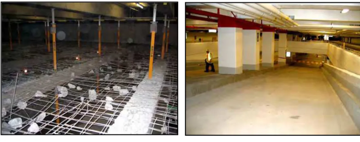
The rehabilitation work consisted of the demolition of the existing structural concrete slabs and ramps (Fig. 1a), surface repair of existing prestressed concrete girders, and construction of new concrete slabs and ramps (Fig. 1b). The elevated formwork and posts were removed after 28 days.
Figure 1a: Slab during demolition (before removal of reinforcement)
Figure 1b: Ramp after reconstruction A minimum of 28 days of wet curing was specified for the concrete slabs and ramps. As required by CSA S413 [1], a polymeric membrane was applied 3 months after the end of the curing period on the surface of the normal concrete slab for moisture and wear protection. No membrane was installed on the hydrophobic concrete slab and ramps, assuming that the hydrophobic admixture will prevent moisture and dissolved chlorides from reaching the steel reinforcement.
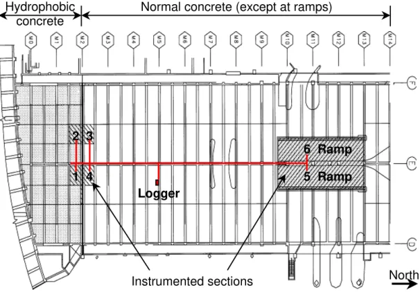
As shown in Fig. 2, four 150-mm thick sections of elevated concrete slab (Nos. 1 to 4) and two 250-mm thick concrete ramps (Nos. 5 and 6) were instrumented to evaluate their performance relative to shrinkage cracking and reinforcement corrosion. Two of the slab sections were built using hydrophobic concrete, and the remaining two were made of normal concrete and used as references for comparison. The reinforcing steel of the slabs consisted of two layers of 10M rebars spaced at 150 mm each way, with a concrete cover of 35 mm. Both ramps were built with hydrophobic concrete. The reinforcing steel of the ramps consisted of two layers of 15M rebars spaced at 150 mm each way, with a concrete cover of 45 mm.
Hydrophobic concrete
Normal concrete (except at ramps)
Instrumented sections
Figure 2: Plan view of parking structure floor
In an effort to prevent restrained shrinkage cracking of the elevated concrete slabs, the concrete was placed in a checkerboard pattern. A 4 x 4 m grid spacing between control joints was used for the hydrophobic concrete floor area (Fig. 2, south of Line M2), and a 8 x 8 m grid spacing was used for the normal concrete floor area (Fig. 2, north of Line M2). Each of the two interior ramps was built using a continuous placement of hydrophobic concrete. Thus, three floor designs are being compared in this study: (i) hydrophobic concrete slab with a 4 x 4 m control joint spacing; (ii) hydrophobic concrete ramps with no control joint, and (iii) normal concrete slab with a 8 x 8 m joint spacing and a polymeric membrane. 1 2 3 4 6 Ramp Logger North 5 Ramp
2.2 Instrumentation
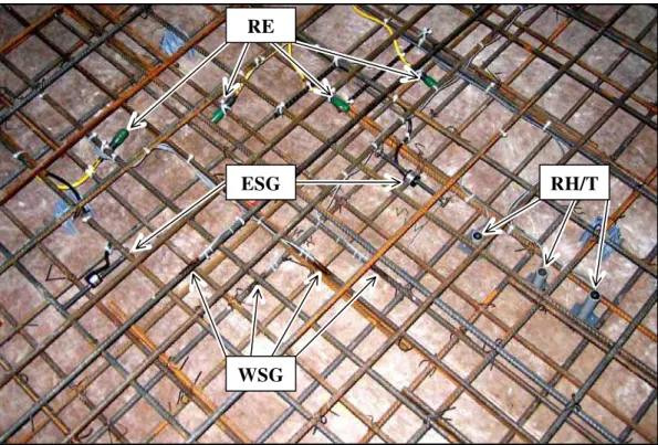
Over 100 sensors were installed in the parking structure. As shown in Fig. 3, each instrumented section includes: (i) three relative humidity and temperature (RH/T) sensors installed in the concrete at different depths to measure drying and temperature profiles; (ii) two embedment strain gauges (ESG) placed in concrete at mid-depth in both directions to measure drying shrinkage and detect cracks; (iii) four 10M 2-m long reinforcing steel bars, each instrumented with two weldable strain gauges (WSG), attached to the top and bottom rebar layers in both directions; and (iv) four manganese dioxide reference electrodes (RE) installed at the top and bottom layers of reinforcement to monitor their corrosion potential.
ESG RH/T
RE
WSG
Figure 3: Typical instrumented section before placement of concrete
An RH/T sensor and a CO2 transmitter were also installed in the ambient
indoor environment of the parking structure near the data logger enclosure. The data acquisition system selected for the field study consisted of a standalone micro-logger and several multiplexers. It was equipped with a modem and a data line for remote communication with the host computer at NRC-IRC. The data acquisition system was installed near the ceiling of the first floor level on the side of a concrete girder. The location of the data logger in the parking structure is indicated in Fig. 2. The sensor cables were routed from the 6 instrumented test sections to the logger via metal conduits in conformance with safety regulations for indoor parking structures. The monitoring started in November 2004 prior to the placement of concrete.
Two instrumented concrete prisms (150 mm high, 300 mm wide and 1000 mm long) were cast on site: one was made with the hydrophobic concrete and the other with the reference concrete. At the end of the 28-day wet curing period, the concrete prisms were transported and stored in NRC-IRC laboratories under environmental conditions similar to those found in the parking structure. The deformations of the prisms due to shrinkage and temperature variations were not mechanically restrained. The relative humidity, temperature and strain of these two concrete prisms were monitored with a portable data acquisition system.
3. Experimental results
The hydrophobic concrete placed in Sections 1, 2, 5 and 6 had slumps varying from 110 to 140 mm, air contents from 3.9 to 4.3 %, and 28-day compressive strengths from 36 to 40 MPa. The reference concrete placed in Sections 3 and 4 had slumps varying from 100 to 120 mm, an air content of 5.2 %, and 28-day compressive strengths from 45 to 54 MPa. 3.1 Hygro-thermal behaviour of concrete
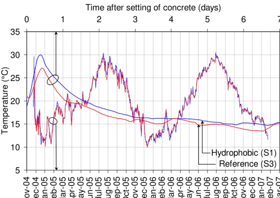
Figure 4 presents the temperature measured at mid-depth in the hydrophobic concrete slab of Section 1 (S1) and the reference concrete slab of Section 3 (S3). A first pair of curves provides detailed temperature data for the first seven days after placement of concrete. A second pair of curves presents the data from November 2004 to March 2007.
5 10 15 20 25 30 35 No v-0 4 De c-0 4 J an-05 F eb-05 Mar-05 Ap r-0 5 May -05 J un-05 Ju l-0 5 A ug-05 S ep-05 Oct-05 No v-0 5 De c-0 5 J an-06 F eb-06 Mar-06 Ap r-0 6 May -06 J un-06 Ju l-0 6 A ug-06 S ep-06 Oct-06 No v-0 6 De c-0 6 J an-07 F eb-07 Mar-07 Time T e mperature (°C ) 0 1 2 3 4 5 6 7
Time after setting of concrete (days)
Hydrophobic (S1) Reference (S3)
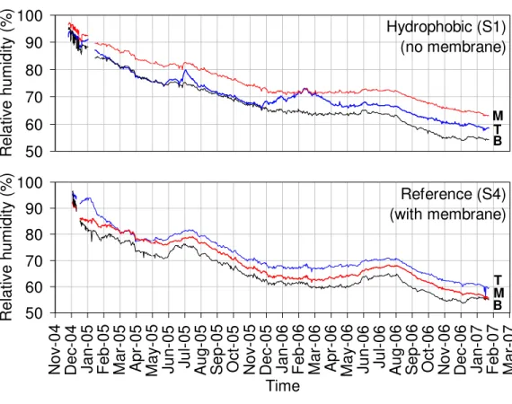
Figure 4 shows that the first 12 hours were marked by a moderate increase in temperature due to the heat released by cement hydration, followed by a cooling period. No major differences in temperature can be observed between the two types of concrete. In the long term, the concrete temperature followed a typical seasonal pattern, from 10°C in the winter to 30°C in the summer. Note that heating and air conditioning in this indoor parking structure maintained reasonable ambient temperatures. Figure 5 presents the RH measured in Sections 1 and 4 at different depths, i.e. at 45 mm from the top slab surface (T), at mid-depth (M) and at 45 mm from the bottom slab surface (B). It can be observed that the drying profile of the hydrophobic concrete slab is typical of slabs with two exposed surfaces, with the RH being higher at mid-depth than at the top and bottom surfaces at any given time. The drying profile of the reference concrete slab is typical of slabs drying from the bottom surface only, with lower RH at the bottom of the slab than at mid-depth and the top surface where the membrane is installed. The hydrophobic concrete slab seems to be less sensitive to ambient RH fluctuations than the reference concrete slab (see peaks in July 2005 and July 2006). This characteristic of the hydrophobic concrete may be inherent to its hydrophobic nature, however, both types of concrete reached relatively low values of RH below 60% after two years of drying. Shortly, the RH will most likely decrease below 50% in both types of concrete, at which level the risk of reinforcement corrosion can be considered low in uncracked concrete [2].
50 60 70 80 90 100 No v-0 4 De c-0 4 Jan-05 F eb-0 5 Ma r-0 5 A p r-0 5 Ma y -05 J u n-05 Ju l-0 5 A ug-05 S ep-0 5 Oct-05 No v-0 5 De c-0 5 Jan-06 F eb-0 6 Ma r-0 6 A p r-0 6 Ma y -06 J u n-06 Ju l-0 6 A ug-06 S ep-0 6 Oct-06 No v-0 6 De c-0 6 Jan-07 F eb-0 7 Ma r-0 7 Time Re la ti v e h u m id it y ( % ) Reference (S4) (with membrane) T M B 50 60 70 80 90 100 R e la ti v e hum idi ty ( % ) Hydrophobic (S1) (no membrane) M T B
A difference of approximately 10% RH across the depth of the concrete slabs was found at any given time. This non-uniform drying profile may result in differential shrinkage cracking at the surface due to the self-restraint caused by the more pronounced drying at the exposed surface than at mid-depth or the unexposed surface. With regard to reinforcement corrosion, this cracking may be more problematic for the hydrophobic concrete slab with the top surface exposed (no membrane).
3.2 Volume change of concrete
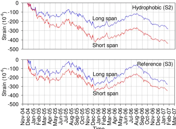
Figure 6 illustrates the total strain (incl. the shrinkage and thermal components) measured at mid-depth in Sections 2 and 3 along the short and long span directions. It can be observed that the total strain in the short span direction is always larger than in the long span direction. This is due to the lower stiffness of the girder/floor system in the short span direction than in the long span direction, resulting in a larger component of free shrinkage. Over time, both types of concrete reached similar levels of total strain. -500 -400 -300 -200 -100 0 St ra in ( 1 0 -6 ) Long span Hydrophobic (S2) Short span -500 -400 -300 -200 -100 0 No v-0 4 De c-0 4 Jan-05 F eb-0 5 Ma r-0 5 A p r-0 5 Ma y -05 J u n-05 Ju l-0 5 A ug-05 S ep-0 5 Oct-05 No v-0 5 De c-0 5 Jan-06 F eb-0 6 Ma r-0 6 A p r-0 6 Ma y -06 J u n-06 Ju l-0 6 A ug-06 S ep-0 6 Oct-06 No v-0 6 De c-0 6 Jan-07 F eb-0 7 Ma r-0 7 Time S trai n (1 0 -6 ) Reference (S3) Long span Short span
Figure 6: Measured concrete total strain
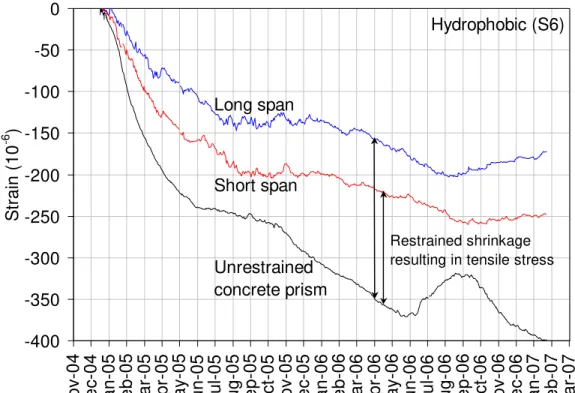
Figure 7 presents the calculated net shrinkage strain (i.e. thermal strain component removed) in the hydrophobic concrete ramp (Section 6) along the short and long span directions, as well as the net shrinkage strain in the corresponding unrestrained hydrophobic concrete prism. Assuming
that the in-situ concrete in Section 6 is subjected to similar environmental conditions as the concrete in the unrestrained prism, their shrinkage strain curves can be compared to estimate the tensile stresses generated in the in-situ test sections. For any given time, the elastic tensile stress will be proportional to the amount of restrained shrinkage strain, which can be calculated as the difference between the in-situ shrinkage strain (measured under partial restraint) and the shrinkage strain in the concrete prism (measured under free shrinkage).
-400 -350 -300 -250 -200 -150 -100 -50 0 No v-0 4 De c -0 4 Ja n -0 5 F e b-05 Ma r-0 5 Ap r-0 5 Ma y -0 5 Ju n -0 5 Ju l-0 5 Au g -0 5 S e p-05 Oc t-05 No v-0 5 De c -0 5 Ja n -0 6 F e b-06 Ma r-0 6 Ap r-0 6 Ma y -0 6 Ju n -0 6 Ju l-0 6 Au g -0 6 S e p-06 Oc t-06 No v-0 6 De c -0 6 Ja n -0 7 F e b-07 Ma r-0 7 Time St ra in ( 1 0 -6 ) Hydrophobic (S6) Long span Short span Unrestrained concrete prism Restrained shrinkage resulting in tensile stress
Figure 7: Calculated net shrinkage strain
3.3 Concrete stress and cracking
The concrete tensile stress in the instrumented sections of floor was
calculated as the result of two major effects: (i) external restraint (Kext)
from the girders, surrounding slabs and reinforcement, resulting in a
uniform component of tensile stress; and (ii) internal self-restraint (Kint)
from differential shrinkage, resulting in a varying component of tensile stress along the depth of the floor. To account for the aging viscoelastic behaviour of concrete, the effective modulus of elasticity of the concrete was calculated as a function of time using the calculation procedures suggested in CSA A23.3 [3] and CEB Model Code [4].
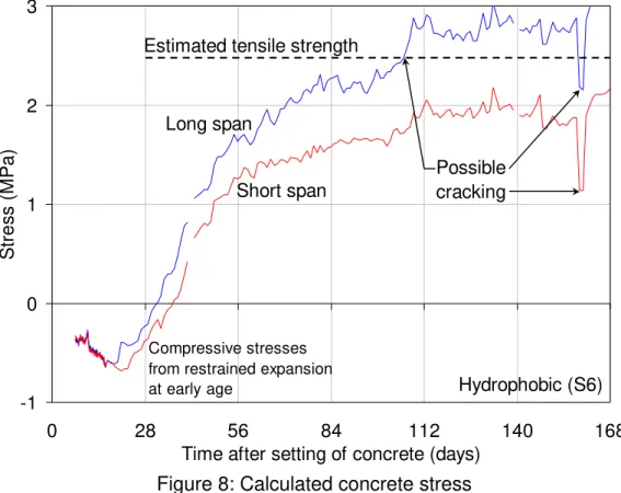
For the hydrophobic concrete ramp (Section 6), Figure 8 presents the calculated tensile stress developing in both directions for the first 6
months. The tensile stress in the long span direction was quite significant and reached the tensile strength after nearly 4 months.
-1 0 1 2 3 0 28 56 84 112 140 168
Time after setting of concrete (days)
S
tres
s
(MP
a)
Estimated tensile strength
Hydrophobic (S6) Possible cracking Short span Long span Compressive stresses from restrained expansion at early age
Figure 8: Calculated concrete stress
The stress results calculated for all six sections were used to determine whether the concrete near the strain gauges had cracked or not. Cracking occurred in all test sections regardless of the type of concrete used. The cracks were detected either within the gauge length (e.g. sudden increase in strain, resulting in stress reaching the estimated tensile strength) or near the strain gauge (e.g. sudden decrease in strain and tensile stress, due to energy release after cracking). Visual inspections confirmed the cracking in all test sections.
As part of the program to verify adequate drainage, the contractor carried out flood tests on all new floor surfaces. In the floor areas where this hydrophobic concrete had been placed, water migrated through the cracks to the lower level of the parking structure. As stated earlier, no membrane had been applied in this area. In July 2005, an injection process, initiated from the soffit of the slab and the underside of the ramp, was used in an attempt to seal the cracks. Another flood test was done in January 2006; however, moisture penetration continued to occur around the cracks and at the end of the cracks. It has been decided to apply a waterproofing membrane to the slab area made with hydrophobic concrete.
3.4 Risk of reinforcement corrosion
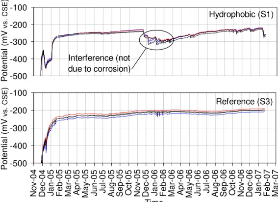
Figure 9 illustrates the corrosion potential of the reinforcement measured by the embedded reference electrodes in Sections 1 and 3. Note that the electrodes were evenly distributed along the top and bottom reinforcement. Within each test section, very little difference in corrosion potential is observed between the units, locations or depths in concrete. It can also be observed that a two-month period was required for the electrodes to reach equilibrium with the surrounding concrete, which is normal. After the initial period, stable potentials between –200 and –250 mV vs. CSE were reached in both types of concrete, which are indicative of a low risk of corrosion of the reinforcement according to ASTM C876 [5]. This is to be expected in a newly rehabilitated parking structure.
-100 -200 -300 -400 -500 P o te n tia l ( m V vs. CS E ) Hydrophobic (S1) Interference (not due to corrosion) -100 -200 -300 -400 -500 No v-0 4 De c-0 4 J an-05 F eb-05 Mar-05 Ap r-05 May -05 J un-05 Ju l-0 5 A ug-05 S ep-05 Oct-05 No v-0 5 De c-0 5 J an-06 F eb-06 Mar-06 Ap r-06 May -06 J un-06 Ju l-0 6 A ug-06 S ep-06 Oct-06 No v-0 6 De c-0 6 J an-07 F eb-07 Mar-07 Time P o te n tia l ( m V vs. CS E ) Reference (S3)
Figure 9: Measured corrosion potential of steel reinforcement 4. Overall performance of hydrophobic concrete slabs and ramps During the two-year period of monitoring reported in this paper, several physical parameters were measured in each instrumented floor section of the parking structure. The data on concrete temperature and relative humidity indicated no exception to the normally-expected hygro-thermal behaviour of the monitored concrete sections. The trends in the corrosion potential data indicated negligible risk of corrosion; however, this was expected, as only two years have elapsed since the rehabilitation work.
The relatively dry concrete floor, with the RH approaching 50%, should also ensure low risks of steel corrosion in uncracked concrete.
The strain data allowed a complete analysis of the restrained shrinkage, tensile stress and concrete cracking occurring at early age in the instrumented floor sections. From the analysis of stresses and cracking, the following observations could be made:
1. The type and number of early-age cracks in the instrumented hydrophobic concrete floor sections were not significantly different from those found in the instrumented reference concrete floor sections. The measured strain data, stress calculations and visual inspections confirmed that these cracks were the results of drying shrinkage under restrained conditions.
2. The measured strains and visual inspections showed no improvement in the reduction of restrained shrinkage cracking by decreasing the spacing between control joints, from no joints in the 28-m long hydrophobic ramps, to the 8-m joint spacing in the normal concrete floor, to the 4-m joint spacing in the hydrophobic concrete floor.
3. In this structure, degrees of restraint as high as 50% and 40% were measured along the long and short span directions, respectively. It is clear from the above observations that neither types of concrete were able to withstand the severe tensile stresses generated at early-age in the hardening concrete slabs and ramps as a result of restrained shrinkage.
5. Conclusions
From the analysis of the results, the following conclusions can be drawn: • In all six instrumented floor sections, the concrete tensile stress due to
restrained shrinkage reached the estimated 28-day tensile strength. Visual inspections and a flood test confirmed the presence of deep cracks in both the hydrophobic and normal concrete floor areas.
• The initial properties of this type of hydrophobic concrete placed in the instrumented floor sections were found satisfactory, with adequate slump (> 110 mm), air content (> 3.9%), and a 28-day compressive strength exceeding the specified strength of 35 MPa. A delay in early strength gain and a lower 28-day strength was observed for the hydrophobic concrete (average of 38 MPa) when compared to the reference concrete (average of 50 MPa).
• The temperature and relative humidity measurements indicated that the type of concrete (hydrophobic or normal) had no significant influence on the drying and thermal expansion of concrete. A typical concrete drying pattern was observed in this indoor structure, ranging from 100% shortly after the concrete was placed to below 60% two years later. As
expected, more drying occurred near the exposed concrete surface than at mid-depth or the unexposed surface, with a differential drying of 10% RH along the depth of the floor, resulting in differential shrinkage. • The shrinkage strain values in the short span direction of the
instrumented sections were always larger than in the long span direction. As expected, movement was less restrained in the short span direction (40% degree of restraint) than in the long span direction (50% degree of restraint).
• The measured strains and visual inspections confirmed that the 4-m grid spacing used between the control joints of the hydrophobic concrete slab did not minimize restrained shrinkage cracking compared to the larger 8-m joint spacing used for the normal concrete slab.
• The corrosion potential measured on the reinforcement reached stable values between –200 and –250 mV vs. CSE, regardless of concrete types or locations in the instrumented sections. This is indicative of a low risk of corrosion of the reinforcement. This is to be expected in a newly rehabilitated structure after only two years.
• The hydrophobic admixture used in the concrete was not effective at preventing the migration of moisture through the floor. This required the decision to install a waterproofing membrane on the slab area made with this hydrophobic concrete.
• Given the extensive floor cracking, long term monitoring is recommended to track the corrosion resistance of the reinforcement. 6. Acknowledgments
The authors wish to thank PWGSC Innovations and Solutions Program for their financial support. Special thanks to Mr. David Delicate, Project Manager of the Laurier Taché Parking Garage Rehabilitation Project for PWGSC, PCL Constructors Eastern Inc. and Genivar - Harmer Podolak for their cooperation and help. The assistance of Dr. L. Mitchell and Mr. G. Pye of NRC-IRC is also gratefully acknowledged.
7. References
[1] CSA S413, Parking Structures – Structures Design, S413, Canadian Standards Association, Toronto, Canada, 1994, 103 p.
[2] ACI 222, Protection of Metals in Concrete Against Corrosion, American Concrete Institute, Farmington Hills, USA, 2001, 41 p.
[3] CSA A23.3, Design of concrete structures, A23.3, Canadian Standards Association, Toronto, Canada, 2004, 214 p.
[4] CEB, CEB-FIP Model Code 1990, Comité Euro-International du béton, Lausanne, Switzerland, 1993, 437 p.
[5] ASTM C876, Standard Test Method for Half-Cell Potentials of Uncoated Reinforcing Steel in Concrete, American Society for Testing and Materials, West Conshohocken, USA, 1999, 6 p.