Publisher’s version / Version de l'éditeur:
Vous avez des questions? Nous pouvons vous aider. Pour communiquer directement avec un auteur, consultez la
première page de la revue dans laquelle son article a été publié afin de trouver ses coordonnées. Si vous n’arrivez pas à les repérer, communiquez avec nous à [email protected].
Questions? Contact the NRC Publications Archive team at
[email protected]. If you wish to email the authors directly, please see the first page of the publication for their contact information.
https://publications-cnrc.canada.ca/fra/droits
L’accès à ce site Web et l’utilisation de son contenu sont assujettis aux conditions présentées dans le site LISEZ CES CONDITIONS ATTENTIVEMENT AVANT D’UTILISER CE SITE WEB.
Fifth International Conference on Concrete under Severe Conditions Environment and Loading (CONSEC'07) [Proceedings], pp. 1-10, 2007-06-04
READ THESE TERMS AND CONDITIONS CAREFULLY BEFORE USING THIS WEBSITE. https://nrc-publications.canada.ca/eng/copyright
NRC Publications Archive Record / Notice des Archives des publications du CNRC : https://nrc-publications.canada.ca/eng/view/object/?id=bcd31c50-5ecc-43ef-b213-de428e4f47d4 https://publications-cnrc.canada.ca/fra/voir/objet/?id=bcd31c50-5ecc-43ef-b213-de428e4f47d4
NRC Publications Archive
Archives des publications du CNRC
This publication could be one of several versions: author’s original, accepted manuscript or the publisher’s version. / La version de cette publication peut être l’une des suivantes : la version prépublication de l’auteur, la version acceptée du manuscrit ou la version de l’éditeur.
Access and use of this website and the material on it are subject to the Terms and Conditions set forth at Corrosion inhibiting systems for concrete bridges - 10 years of field performance evaluation
C o r r o s i o n i n h i b i t i n g s y s t e m s f o r c o n c r e t e
b r i d g e s – 1 0 y e a r s o f f i e l d p e r f o r m a n c e
e v a l u a t i o n
N R C C - 4 9 2 0 7
C u s s o n , D . ; Q i a n , S .
A version of this document is published in / Une version de ce document se trouve dans: Fifth International Conference on Concrete under Severe Conditions Environment and Loading (CONSEC’07), Tours, France, June 4-6, 2007, pp. 1-10
The material in this document is covered by the provisions of the Copyright Act, by Canadian laws, policies, regulations and international agreements. Such provisions serve to identify the information source and, in specific instances, to prohibit reproduction of materials without written permission. For more information visit http://laws.justice.gc.ca/en/showtdm/cs/C-42
Les renseignements dans ce document sont protégés par la Loi sur le droit d'auteur, par les lois, les politiques et les règlements du Canada et des accords internationaux. Ces dispositions permettent d'identifier la source de l'information et, dans certains cas, d'interdire la copie de documents sans permission écrite. Pour obtenir de plus amples renseignements : http://lois.justice.gc.ca/fr/showtdm/cs/C-42
CONSEC’07 Tours, France Concrete under Severe Conditions : Environment & Loading F. Toutlemonde et al. (eds)
CORROSION INHIBITING SYSTEMS FOR CONCRETE BRIDGES –
10 YEARS OF FIELD PERFORMANCE EVALUATION
SYSTÈMES INHIBITEURS DE CORROSION POUR PONTS EN BÉTON – 10 ANS D’ÉVALUATION DE LA PERFORMANCE IN SITU
Daniel CUSSON and Shiyuan QIAN
National Research Council Canada, Institute for Research in Construction, Ottawa, Canada
ABSTRACT: The performance of nine corrosion-inhibiting systems for reinforced concrete structures exposed to the severe Canadian climate was assessed in the field on bridge barrier walls. These systems were composed of one or more of the following components: concrete admixtures, reinforcing steel coatings, and/or concrete surface coatings/sealers. The field evaluation consisted of annual corrosion surveys of half-cell potential and corrosion rate, as well as laboratory testing on concrete cores. After ten years, the main reinforcement at a depth of 75 mm was found in relatively good condition. Special bars embedded at a depth of 13-mm showed signs of advanced corrosion for all systems. Non-destructive corrosion evaluation of 25-mm deep special bars indicated lower risks of corrosion for corrosion-inhibiting systems composed of concrete admixtures.
RÉSUMÉ: La performance in situ de neuf systèmes anticorrosion pour structures en béton armé exposées au sévère climat canadien a été évaluée sur des parapets de pont. Ces systèmes étaient composés d’un ou de plusieurs des composants suivants: adjuvants à béton, revêtements d’armature, et/ou des scellants/revêtements de surface pour béton. L’évaluation comportait des mesures annuelles du potentiel et de la vitesse de corrosion, ainsi que des essais sur des carottes de béton. Après dix ans, l’armature principale, placée à une profondeur de 75 mm, était encore en bon état. Des barres spéciales enfouies à 13 mm de profondeur ont montré des signes de corrosion avancée pour tous les systèmes testés. L’évaluation non destructive de barres enfouies à 25 mm de profondeur a démontré des risques de corrosion plus faibles pour les systèmes composés d’adjuvants à béton.
Introduction
The main cause of deterioration of concrete bridges in Canada is chloride-induced corrosion of steel reinforcing bars. Amongst different protection techniques, corrosion inhibitors are considered as one of the most cost-effective solutions. The mechanisms by which they protect the reinforcing steel from corrosion are often complex. Yet very little information exists on the long-term performance of concrete structures built with corrosion-inhibiting systems. This paper presents the results of a 10-year study of the field performance of nine corrosion-inhibiting systems applied on a major highway bridge near Montreal, Canada. Field corrosion measurements, including half-cell potential and corrosion rate were performed over the reinforcement of the bridge barrier walls. Additional laboratory tests on concrete cores were also carried out. The main objectives of this investigation were: (i) to evaluate the in-service performance of rehabilitated concrete structures subject to the simultaneous effects of de-icing salt contamination, freeze-thaw and wet-dry cycles; and (ii) to identify the most effective corrosion-inhibiting systems in the field.
Experimental investigation
Test structure and rehabilitation work
In 1996, the Ministry of Transportation of Québec undertook a major rehabilitation of the Vachon bridge located North of Montreal. Part of the rehabilitation work consisted in rebuilding the barrier walls. This 6-lane wide, 714-m long bridge has twenty-one 34-m long single spans consisting of prestressed concrete girders supporting a reinforced concrete slab. Ten consecutive spans of the East-side barrier wall were selected as the test site for the application of commercial corrosion inhibiting systems.
Eight spans of the barrier wall were built using a standard concrete mix and conventional carbon-steel reinforcement. Each span included a different corrosion inhibiting system (described in Table I), which was provided and installed by its manufacturer. Two other test spans were built using the same concrete but with no corrosion inhibitors: one span had carbon-steel reinforcement (identified as “Control Span”), and the other span had epoxy-coated carbon-steel reinforcement (identified as “Epoxy Span”). The main reinforcement consisted of eight 15-mm longitudinal bars in the cross-section, and 15-mm transverse bars spaced at 230 mm along the barrier wall length. The concrete had a water-cement ratio of 0.36, a CSA Type 10 cement content of 450 kg/m3, an air content of 6.5%, a slump of 80 mm, and an average 28-day compressive strength of 45 MPa. The placement of concrete took place in October 1996.
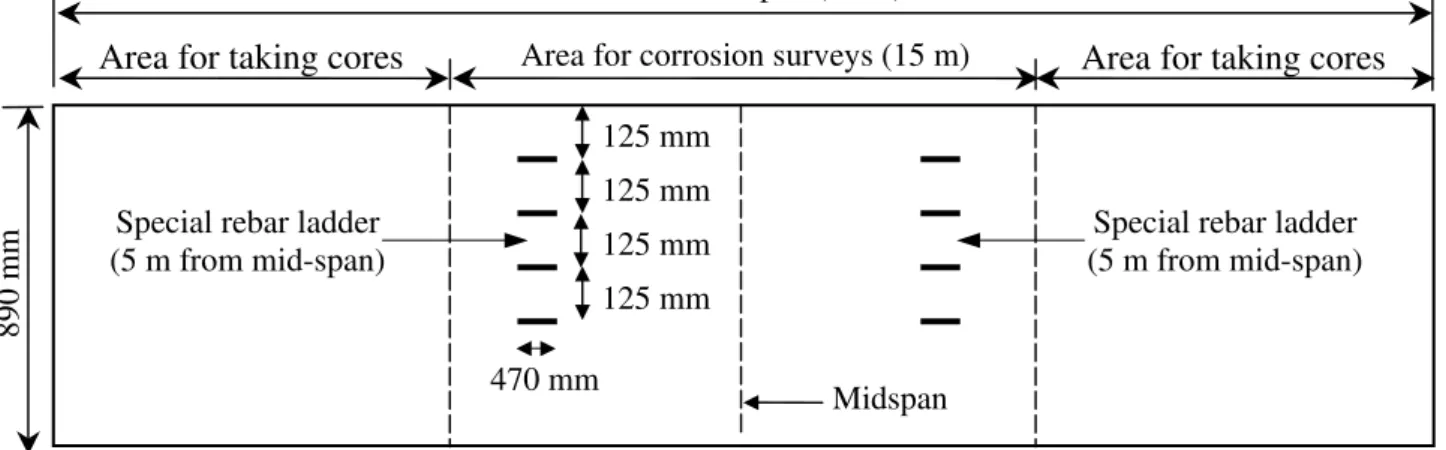
Each corrosion-inhibiting system was applied over the 34-m length of its assigned test span of barrier wall. As illustrated in Figure 1, non-destructive corrosion testing was limited to the 15-m central portion of the span. Concrete cores for laboratory testing of strength, permeability and chloride content were usually taken just outside this 15-m central portion; and embedded instrumentation for remote monitoring was installed at mid-span. The details of the remote monitoring system can be found in Qian and Cusson (2004).
Table I. Generic description of the investigated corrosion-inhibiting systems.
Name Generic description †
Control - Carbon-steel reinforcement Epoxy - Epoxy-coated reinforcement
A - Rebar coating (water-based liquid blend, Portland cement and fine silica sand) - Concrete coating (polymer-based liquid blend, Portland cement and aggregates) B - Organic concrete admixture (alkanolamines)
- Coating only on vertical anchor bars from slab (water-based epoxy, Portland cement) C - Organic/inorganic concrete admixture (amine derivatives, sodium nitrite)
D - Rebar coating (water-based epoxy, cementitious components) E - Organic concrete admixture (amines and esters)
F - Organic concrete admixture (alkanolamines and amines, and their salts with organic/inorganic acids)
G - Organic concrete admixture (alkanolamines, ethanolamine and phosphate)
- Coating only on vertical anchor bars from slab (water-based epoxy, Portland cement) - Concrete sealer (water-repellent penetrating silane)
H - Inorganic concrete admixture (calcium nitrite)
† Commercial names are not identified to maintain the anonymity of the manufacturers.
CONSEC’07 Tours, France
Area for corrosion surveys (15 m) Entire test span (34 m)
Special rebar ladder (5 m from mid-span) 890 mm Midspan 470 mm 125 mm 125 mm
Area for taking cores Area for taking cores
Special rebar ladder (5 m from mid-span) 125 mm
125 mm
Figure 1. Schematic elevation view of a typical test span of barrier wall (not to scale).
On-site corrosion measurements
On-site corrosion surveys of the barrier wall were performed annually during the months of May/June from 1997 to 2006, including measurements of half-cell potential, corrosion rate and concrete resistivity. These surveys were conducted under similar environmental conditions, including ambient temperature (15-25°C) and concrete surface condition. A saturated copper sulphate electrode CSE and a high input impedance voltmeter were used to measure the half-cell potential following the ASTM C876 procedure. The measurements were taken at 110, 345 and 550 mm from the top of the 890-mm high barrier wall, and horizontally at 300-mm intervals over the central 15-m portion of each test span. A Gecor 6 instrument was used to measure the corrosion rate of steel in concrete by the polarization resistance technique. In each span, measurements were taken on vertical and horizontal bars at cracked and uncracked locations.
For early detection of corrosion and early performance evaluation of the corrosion inhibiting systems, two sets of rebar ladders were embedded in each test span during construction; except in the control concrete, in which four sets of ladders were embedded. Half-cell potentials and corrosion rates were taken over these ladders using the instruments and methods described above. Each ladder was made of four 470-mm long horizontal bars (10-mm diameter) spaced at 125 mm center to center. The ladder bars had varying concrete cover thicknesses ranging from 13 mm for the upper bar, and 25 mm, 38 mm and 50 mm for the 3 other horizontal bars, respectively.
Data analysis
Prevailing conditions at the bridge
A visual inspection of the barrier wall, carried out a few days after casting, revealed closely spaced vertical cracks running through the walls, raising a concern for premature rebar corrosion due to accelerated moisture and salt ingress and eventual spalling of the concrete. These vertical cracks had an average spacing of 800 mm. Most cracks had a width of 0.2 mm or less, with a few having openings of 0.3 mm. A study by Cusson and Repette (2000) was conducted to determine the underlying causes of this problem using time-dependent numerical models and measured field data. It was confirmed that the early-age cracking was mainly due to uncontrolled thermal effects and autogenous shrinkage under restrained conditions, typical of concrete with high cement content and low water-cement ratio.
A rise in temperature can increase the rate of corrosion. The moisture level in concrete also influences reinforcement corrosion as it affects carbonation, chloride ingress, electrical resistivity, and oxygen level. Such information is therefore useful for the adequate analysis of the parameters that govern the field performance of the concrete systems. The measured concrete temperature typically varied from –15°C in January to +35°C in August. The relative humidity (RH) in the concrete barrier wall followed a seasonal pattern with high RH measured in May-June (frequent rainy periods) and lower RH in December-January (cold and dry periods). Overall, the concrete RH decreased over the years as a result of drying towards values near 80% ± 5% after 10 years. According to ACI Committee 222, the risk of corrosion can be considered low in dry concrete when RH is lower than 50% due to an impeded electrolytic process, or in fully saturated concrete (near 100% RH) due to low oxygen concentration.
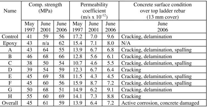
Concrete properties measured on cores taken from barrier wall
Table II presents the compressive strengths measured on concrete cores taken from the barrier wall in May 1997 (i.e. 6 months after construction), June 2001 and June 2006. As cement hydration proceeded, the overall compressive strength increased by 38 % in four years, with no significant change thereafter. Similarly, the water vapour permeability coefficients decreased in the first 4 years and remained constant after. All the coefficients of permeability measured in 1997 can be considered representative of moderate permeability; however, all those measured in 2001 and 2006 are indicative of very low permeability according to Neville (1996), as a result of continued cement hydration. No detrimental effects from these systems on the concrete properties were observed.
Table II. Concrete properties and observed damage. Comp. strength
(MPa)
Permeability coefficient (m/s x 10-12)
Concrete surface condition over top ladder rebar
(13 mm cover) Name May 1997 June 2001 June 2006 May 1997 June 2001 June 2006 June 2006
Control 41 59 56 17.2 7.0 9.6 Cracking, delamination
Epoxy 43 n/a 62 15.4 7.1 8.0 N/A
A 43 64 55 13.9 6.7 6.8 Cracking, delamination, spalling
B 46 68 66 12.8 5.6 6.1 Cracking, delamination
C 38 50 54 10.7 4.6 5.5 Cracking, delamination, spalling
D 39 54 59 12.3 6.7 6.4 Cracking
E 45 69 58 11.5 4.3 4.5 Cracking, delamination, spalling
F 45 60 56 15.9 8.7 7.2 Cracking, delamination, spalling
G 50 68 51 14.9 6.2 9.1 Cracking, delamination
H 55 60 69 14.1 7.3 8.8 Cracking
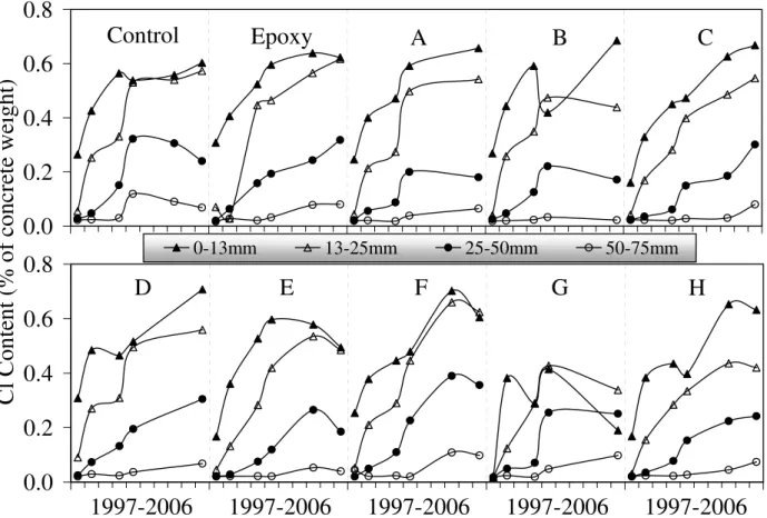
Overall 45 61 59 13.9 6.4 7.2 Active corrosion, concrete damaged The total chloride content (by weight of concrete) was determined on cores taken in the barrier wall from 1997 to 2006, as presented in Figure 2. In general, chloride contents increased over time and decreased with depth, as expected. By 2001, at depths up to 50 mm, the chloride contents in all test spans exceeded the critical threshold value of 0.1% proposed by Stoltzner et al. (1997). This chloride threshold, however, is highly uncertain for concretes containing corrosion inhibitors, which may increase its value. In 2006, at depths of 50-75 mm, the
CONSEC’07 Tours, France
concretes in all test spans had chloride contents below or near the threshold value, suggesting that the risk of corrosion of the main reinforcement was low at uncracked locations. However, localized pitting corrosion was likely to have developed at cracked locations due to the high chloride contents readily available at the rebar level. The concrete in most spans showed quite similar chloride profiles over time, which is consistent with the test results presented in Table II. The system in Span G, however, performed very well in 1997, at which time no chlorides penetrated into the concrete, due to the added sealer at the concrete surface. In the following years, chlorides penetrated into the concrete but at a lower rate than in other systems. It is worth mentioning that this migrating sealer was applied over the thin cement-based parging on the barrier wall surface, which spalled off a year after installation due to severe weathering and abrasion, reducing somewhat the effectiveness of the sealer.
0.0
0.2
0.4
0.6
0.8
Cl Content (% of concrete weight)
0-13mm 13-25mm 25-50mm 50-75mm
0.0
0.2
0.4
0.6
0.8
Control
Epoxy
A
B
C
D
E
F
G
H
1997-2006 1997-2006 1997-2006 1997-2006 1997-2006
Figure 2. Total chloride content obtained on concrete cores from barrier wall.
Observation of corrosion-induced damage
The barrier wall surface was inspected in June 2006 for corrosion-induced damage over Bar #1 of each special embedded ladder, where the concrete cover was 13 mm. The observations are presented in Table II. Horizontal cracking was considered to be the first step in the progression of damage due to rebar corrosion, followed by delamination (determined by a sound test) and/or concrete spalling (exposed rebar). Test Spans D and H had the lowest degree of damage. After 10 years, it can be concluded, however, that corrosion is active on Bar #1 of the ladders in each test span where the concrete cover is only 13 mm.
Concrete cores were taken in June 2006 over Bar #2 of each ladder to visually observe the corrosion of the embedded rebar, for which the concrete cover was 25 mm. After comparing the observations with pictures of the same ladders before installation in the barrier wall in 1996, it was concluded that the corrosion products at the steel surface did not progress significantly on these bars. The fact that chlorides were present at this level since 2001 indicates that active
corrosion should not take too long to initiate in some systems. Note, however, that the amount of chlorides to initiate corrosion may depend on several factors, such as concrete permeability, and the amount and type of corrosion inhibitors, etc. Very little is currently known about the effects of these factors on the corrosion threshold.
A second set of cores was taken in June 2006 over the main reinforcement of the barrier wall where the concrete cover was typically 75 mm. The locations of the cores were chosen to correspond to places where measurements indicated more negative corrosion potentials and higher corrosion rates. After splitting the cores, the observed rebars indicated that no significant active corrosion was present, which can be expected at this depth in very low permeability concrete after 10 years.
Risk of corrosion of the main reinforcement
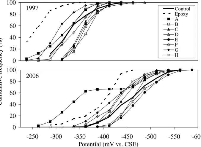
Figure 3 shows the cumulative distributions of half-cell potential obtained in 1997 and 2006. With time, the potentials shifted towards more negative values, indicating an increasing risk of corrosion. The Epoxy Span showed less negative potentials than other spans. This is due to the high electrical resistance of the epoxy coating. A similar trend is seen in 2006 on Span A, for which the bars were covered with a cementitous coating before installation in the barrier wall (i.e. bars are electrically isolated). Not considering Spans Epoxy and A for the above reason, all 2006 curves are within a narrow range of ±30 mV from the control span, suggesting that corrosion is not advanced enough to differentiate one system from another as far as corrosion-inhibiting effectiveness is concerned. This is in agreement with the low chloride contents measured at a depth of 75 mm and the lack of active corrosion observed on the cored rebar samples taken at a depth of 75 mm. It is noted that the control system is already a good system with a low permeability concrete and a thick cover over the main rebars.
0
20
40
60
80
100
-600
-550
-500
-450
-400
-350
-300
-250
Potential (mV vs. CSE)
2006
0
20
40
60
80
100
Control Epoxy A B C D E F G H1997
Cumulative frequency (%)
Figure 3. Cumulative distributions of half-cell potential measured over main reinforcement.
CONSEC’07 Tours, France
Figure 4 shows the average current density measured over the main reinforcement at cracked and uncracked locations, where the cover was 75 mm thick. Initially, the test spans with no coatings on rebars (or on concrete) showed relatively high current densities in 1997 and 1998, which were due to the formation of a protective oxide film on the steel. Afterwards, the current densities decreased in all spans (due to passivation) towards values below 0.5 μA/cm2 (Rodriguez et al., 1994), under which corrosion is not considered active. In general, higher corrosion rates were found at cracked locations than at uncracked locations, with an overall increase of 35% for the nine spans with regular carbon-steel reinforcement.
0.0
0.2
0.4
0.6
0.8
1.0
1.2
Current density (
μA/cm
2)
Cracked locations Uncracked locations
0.0
0.2
0.4
0.6
0.8
1.0
1.2
Control
Epoxy
A
B
C
D
E
F
G
H
1997-2006 1997-2006 1997-2006 1997-2006 1997-2006
Figure 4. Corrosion rate measured over main reinforcement.
Corrosion of the rebar ladders
Figure 5 shows the half-cell potential measured on the rebar ladders for each span (only for Bars #1 and #2). Note that the Epoxy System was not tested on the special ladders. In general, the half-cell potential started at –200 mV and became more negative with time, and more rapidly at Bar #1 (13 mm cover) than at Bar #2 (25 mm cover) due to a higher chloride content near the surface, as expected. Best-fit curves are also shown in Figure 5 for Bar #2; such curves were determined by linear regression analysis of the experimental data. These curves show that Spans H and F had the least negative potentials in 2006 (≥ -550 mV), indicating the lowest risks of corrosion at a depth of 25 mm, compared to the control span and other systems.
Figure 6 presents the corrosion rates measured on the rebar ladders for each span. In general, the corrosion rates were higher on Bar #1 (13 mm cover) than on Bar #2 (25 mm cover), as expected. In 2006, all corrosion rates on Bar #1 exceeded the threshold value of 0.5 μA/cm2
, indicating active corrosion. This is in agreement with the damages observed over Bars #1 of the rebar ladders (see Table II). The best-fit curves of the corrosion rate at Bar #2 show that Spans H and B had the lowest rates in 2006 (≤ 0.2 μA/cm2) for a depth of 25 mm, compared to Control span and other systems. Spans E and F also had low corrosion rates (≤ 0.25 μA/cm2).
-100
-200
-300
-400
-500
-600
-700
Potential (mV vs. CSE)
Bar #1 (13mm deep) Bar #2 (25mm deep)
-100
-200
-300
-400
-500
-600
-700
Control-1
Control-2
A
B
C
D
E
F
G
H
1997-2006 1997-2006 1997-2006 1997-2006 1997-2006
Best-fit for Bar #2Figure 5. Half-cell potential measured over embedded rebar ladders.
0.0
0.5
1.0
1.5
2.0
2.5
Current density (
μA/cm
2)
Bar #1 (13mm deep) Bar #2 (25mm deep)
0.0
0.5
1.0
1.5
2.0
2.5
Control-1
Control-2
A
B
C
D
E
F
G
H
1997-2006 1997-2006 1997-2006 1997-2006 1997-2006
Best-fit for Bar #2Figure 6. Corrosion rate measured over embedded rebar ladders.
CONSEC’07 Tours, France
Overall performance of investigated corrosion inhibiting systems
The performance evaluation of systems having different corrosion-inhibiting mechanisms installed on a concrete structure is a challenging task. On one hand, there is no single test capable of determining the overall performance of a system in the field and; on the other hand, different tests offer conditions of varying severity and type. To provide a meaningful assessment of the overall performance of the corrosion inhibiting systems, the performance of a system should always be evaluated in comparison to that of the control system.
The laboratory tests performed on the concrete cores taken from the barrier wall show that the concretes used for the control and the corrosion inhibiting systems was of very good quality with low permeability to water and chlorides and good compressive strength. With the 75-mm concrete cover over the main reinforcement, the barrier wall in each test span has already a good built-in protection system against corrosion. The corrosion inhibiting systems used in this study should therefore be regarded as a second line of defence against corrosion of the reinforcement, which could be particularly useful when concrete is cracked.
The assessment of the corrosion-induced damage of the concrete surface of the barrier wall over the top ladder rebars (13 mm cover) indicated that corrosion was active in all test spans, with a lower degree of damage on Span H and D (few minor horizontal cracks only). Inspection of the concrete cores taken over the 2nd ladder rebars (25 mm cover) and over the main reinforcement (75 mm cover) showed no significant evidence of active corrosion.
The non-destructive evaluation of corrosion over the main reinforcement indicated that the risks of corrosion in all test spans were still low but slowly increasing. The lack of significant active corrosion found on the main reinforcement, which was protected by a very low permeability concrete and a thick 75-mm cover, explains why no significant differences in performance between the corrosion-inhibiting systems and the control system could be seen after ten years.
In order to observe differences in the corrosion-inhibiting effectiveness of theses systems, the above findings suggest that the non-destructive evaluation results taken over Bar #2 of the special ladders (where corrosion is predicted to become active shortly) can give some valuable information. From these results, it seems that System H (inorganic concrete admixture) gave consistently good performance, followed by other systems, such as B, E and F (organic concrete admixtures).
Summary and conclusions
The field performance of ten 34-m spans of a reconstructed bridge barrier wall protected with nine proprietary corrosion-inhibiting systems and one control system were evaluated for 10 years (1996-2006). The bridge structure was exposed to the severe Canadian climate. The field performance of the corrosion-inhibiting systems was evaluated mainly from measurements of half-cell potential and corrosion rate and from inspections of concrete surface and cored rebars. The major conclusions of this field investigation can be summarized as follows:
• The properties measured in the laboratory on concrete cores taken from the barrier wall are indicative of a very good quality concrete, with a very low permeability and a compressive strength far exceeding its 35 MPa design requirement.
• Total chloride contents measured after 10 years at a depth of 50-75 mm remained below or near the critical chloride threshold of 0.1% in all test spans. This suggests that the risk of corrosion of the 75-mm deep reinforcement was still low at uncracked locations.
• The migrating sealer of System G performed very well in 1997, at which time practically no chlorides penetrated into the concrete. In the following years, chlorides penetrated into the concrete but at a significantly lower rate than in the other systems with no sealers at the surface of the barrier wall.
• Corrosion-induced damage of the barrier wall surface over the 13-mm deep bars of the special embedded ladders was found in all test spans, with the least damage on Spans H and D (minor cracks). Note that the Epoxy System was not tested on the special rebar ladders. • Inspection of concrete cores taken over the 25-mm deep ladder bars and the 75-mm deep
main reinforcing bars indicated no clear evidence of active corrosion in all test spans. This is due to the very good quality of the concrete used in the construction of the barrier wall (i.e. very low water permeability).
• Non-destructive evaluation of the corrosion over the 75-mm deep main reinforcement could not differentiate one system from another as far as corrosion-inhibiting effectiveness is concerned, since no substantial corrosion has occurred after 10 years.
• Corrosion rates on the main reinforcement measured over the vertical shrinkage cracks (which appeared shortly after construction) were consistently higher than those measured over uncracked locations, regardless of the corrosion-inhibiting systems used, including the system with epoxy-coated reinforcement.
• Non-destructive evaluation of the corrosion over the 25-mm deep ladder rebars indicated that System H (inorganic concrete admixture) gave consistently good performance, with a reduced risk of corrosion, followed by Systems B, E and F (organic concrete admixtures) in comparison to the control system.
Acknowledgements
The financial contributions of our project partners are gratefully acknowledged, namely: Ministère des transports du Québec, IRAP, and all the product manufacturers who participated in this study. The sustained assistance of Louis-Marie Bélanger and Daniel Vézina from MTQ is also gratefully acknowledged. The authors would also like to thank Noel Mailvaganam, Roger Willoughby, Bruce Baldock, Nathalie Chagnon, Rock Glazer, Ted Hoogeveen, Gordon Chan, Mark Arnott and Mark Lowery from NRC for their valuable assistance.
References
ACI Committee 222 (2001) Protection of metals in concrete against corrosion, American Concrete Institute, Farmington Hills, 41 pp.
Cusson, D., and Repette, W. (2000) Early-age cracking in reconstructed concrete bridge barrier walls, ACI Materials Journal, 97(4), July/August, 438-446.
Neville, A. M. (1996) Properties of concrete, 4th ed., John Wiley & Sons, Inc., ed., New-York, 844 pp.
Qian, S.Y. and Cusson, D. (2004) Electrochemical Evaluation of the Performance of Corrosion-Inhibiting Systems in Concrete Bridges, Cement & Concrete Composites, 26, 217-233. Rodriguez, J., Ortega, L.M., Garcia, A.M. (1994) Assessment of structural elements with
corroded reinforcement, Proceedings of the International Conference on Corrosion, Sheffield, U.K., July, 16 p.
Stoltzner, E., Knudsen, A., and Buhr, B. (1997) Durability of marine structures in Denmark, Proceedings of the International Conference on Repair of Concrete Structures From Theory to Practice in a Marine Environment, A. Blankvoll, ed., Svolvaer, Norway, May, 59-68.