Publisher’s version / Version de l'éditeur:
Vous avez des questions? Nous pouvons vous aider. Pour communiquer directement avec un auteur, consultez la
première page de la revue dans laquelle son article a été publié afin de trouver ses coordonnées. Si vous n’arrivez pas à les repérer, communiquez avec nous à PublicationsArchive-ArchivesPublications@nrc-cnrc.gc.ca.
Questions? Contact the NRC Publications Archive team at
PublicationsArchive-ArchivesPublications@nrc-cnrc.gc.ca. If you wish to email the authors directly, please see the first page of the publication for their contact information.
https://publications-cnrc.canada.ca/fra/droits
L’accès à ce site Web et l’utilisation de son contenu sont assujettis aux conditions présentées dans le site
LISEZ CES CONDITIONS ATTENTIVEMENT AVANT D’UTILISER CE SITE WEB.
Proceedings of the Canadian Symposium on Roofing Technology: 31 March 2009, Toronto, pp. 1-9, 2009-04-01
READ THESE TERMS AND CONDITIONS CAREFULLY BEFORE USING THIS WEBSITE.
https://nrc-publications.canada.ca/eng/copyright
NRC Publications Archive Record / Notice des Archives des publications du CNRC :
https://nrc-publications.canada.ca/eng/view/object/?id=a481d534-4e33-4510-9c6a-9f4c505e137c https://publications-cnrc.canada.ca/fra/voir/objet/?id=a481d534-4e33-4510-9c6a-9f4c505e137c
NRC Publications Archive
Archives des publications du CNRC
This publication could be one of several versions: author’s original, accepted manuscript or the publisher’s version. / La version de cette publication peut être l’une des suivantes : la version prépublication de l’auteur, la version acceptée du manuscrit ou la version de l’éditeur.
Access and use of this website and the material on it are subject to the Terms and Conditions set forth at
Air intrusion vs. air leakage - the dilemma for low sloped mechanically attached membrane roofs
http://irc.nrc-cnrc.gc.ca
Air int rusion vs. a ir le a k a ge - t he dile m m a for low
slope d m e cha nic a lly at t a che d m e m bra ne roofs
N R C C - 5 1 2 4 0
M o l l e t i , S . ; B a s k a r a n , B . A . ; K o , K . P . ; B e a u l i e u , P .
A p r i l 2 0 0 9
A version of this document is published in / Une version de ce document se trouve dans:
Proceedings of the Canadian Symposium on Roofing Technology, Toronto, ON., March 31 – April 1, 2009, pp. 1-9
The material in this document is covered by the provisions of the Copyright Act, by Canadian laws, policies, regulations and international agreements. Such provisions serve to identify the information source and, in specific instances, to prohibit reproduction of materials without
written permission. For more information visit http://laws.justice.gc.ca/en/showtdm/cs/C-42
Les renseignements dans ce document sont protégés par la Loi sur le droit d'auteur, par les lois, les politiques et les règlements du Canada et des accords internationaux. Ces dispositions permettent d'identifier la source de l'information et, dans certains cas, d'interdire la copie de
AIR INTRUSION vs. AIR LEAKAGE - THE DILEMMA
for
LOW-SLOPED MECHANICALLY ATTACHED MEMBRANE ROOFS
Suda Molleti *, Bas A. Baskaran , Steven Ko, Pascal Beaulieu
National Research Council of Canada
1200 Montreal Road, Ottawa, ON, Canada, K1A OR6
*Corresponding Author. Tel: 613-993-9673;Fax:613-998-6802;sudhakar.molleti@nrc.ca
Majority of low-sloped roofs are constructed as conventional membrane roofing assemblies (membrane above insulation). Currently, four types of conventional assemblies are typically in use:
1. Mechanically attached assembly, 2. Loose-laid ballasted assembly,
3. Fully- bonded assembly (insulation fastened and membrane adhered), and 4. Adhesive applied assembly (all components fully adhered).
Approximately one fourth of North American low slope/commercial buildings are roofed with mechanically attached assemblies (NRCA 2004) and their popularity continues to grow. The present paper differentiates the air intrusion and air leakage performance of the mechanically attached assembly.
The waterproofing membrane, the key component of mechanically attached roofs, is available in three different types:
Modified bituminous membranes (Mod-Bit) i.e. asphaltic based and its width is 3.3 ft. (1 m),
Thermosets include the commonly used ethylene propylene diene monomer (also known as ethylene propylene diene terpolymer (EPDM))
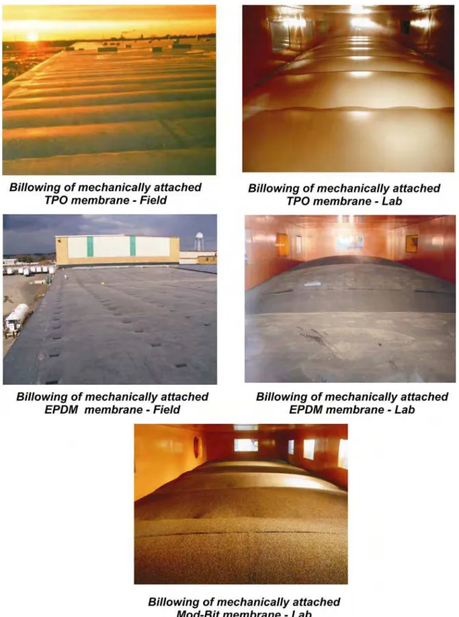
Thermoplastics encompass a wider variety of roofing membranes, the most common of which are poly vinyl chloride (PVC) and thermoplastic olefin (TPO). Both thermoset and thermoplastic membranes employ different seaming techniques due to their different chemical, physical and mechanical properties. They are typically available in widths from 6 to 12 ft. (1.8 to 3.6 m). Membranes are installed in sheets and attached to the structural substrate (such as steel deck) using mechanical fasteners. The attachment locations are then overlapped as seams, which are jointed using different seaming techniques specific to the membrane type. Figure 1 shows the membrane response of the three different mechanically attached assemblies for both field and laboratory conditions.
Figure 1: Field and laboratory response of mechanically attached membrane roofs
Although research has been directed to the characterization of individual roof components, such as membrane, relatively little attention has been given to how air movement affects system performance. It has been incorrectly assumed that air movement in roofing assemblies is similar to air movement in wall assemblies. Several factors contribute to this misconception including existing energy and building code
requirements and the current air barrier standards, which are all focused on wall assemblies. Kalinger (2008) clearly points out that “ASTM E2357-05 Standard Test
Method for Determining Air Leakage of Air Barrier Assemblies contains three references
to roofs in contrast to 45 references to walls. He also states that “roofs are not simply horizontal walls, and it is inappropriate to generalize information and requirements relating to wall performance to low-slope roof assemblies.”
Air movement in a building assembly can be defined as follows (Molleti 2008):
Air Leakage: When air enters or leaves one environmental condition and moves to another environmental condition through building envelope assemblies such as walls and windows, it is termed “Air Leakage.”
Air Intrusion: When conditioned indoor air enters into a building envelope assembly but cannot escape to the exterior environment, as is the case for mechanically attached roofs, it is termed “Air Intrusion.”
Figure 2 demonstrates the difference between air leakage and air intrusion. When wind acts on a mechanically attached roof, wind-induced suction lifts the membrane between the attachments and causes membrane elongation and billowing. The magnitude of the wind induced suction and the membrane’s elastic property determines the billow shape. This change in membrane shape leads to a volume change (expansion) of the roof space between the membrane and the deck, creating negative or bubble pressure in that space. To equalize the negative pressure, indoor conditioned air is drawn into the roof assembly.
Figure 2: Air leakage and air intrusion in a building assembly
For mechanically attached membrane roofs, the waterproofing membrane is also the “air barrier.” If constructed properly, it certainly prevents air leaving or entering a building through the roof. From a material perspective, the membrane is impermeable, a fact that can be proven by permeability data (Bomberg and Kumaran 1985, CMHC 1988). However, from an assembly perspective, the question arises whether the interaction between the different roof components caused by wind uplift and resulting in billowing (Figure1) leads to air leakage through a roofing assembly.
The Dynamic Roofing Facility at NRC/IRC, has been conducting research on the wind uplift performance of membrane roofing assemblies for the past decade. CSA A123.21-04 Standard Test Method for the Dynamic Wind Uplift Resistance of Mechanically
Attached Membrane-Roofing Systems was developed at DRF and is the only North American test procedure for assessing the wind load uplift resistance of mechanically attached roofing systems under dynamic wind load conditions. Several roofing configurations have been evaluated using this test protocol and an extensive wind uplift database has been created. One of the key observations from this database is that there is no air leakage in mechanically attached roofing assemblies and there is certainly air intrusion occurs as discussed below.
Figure 3 shows a typical wind uplift performance data of mechanically attached thermoplastic and thermoset roofing assemblies. In this example, the thermoplastic
membrane sustained a wind uplift pressure of 90 psf (4.3 kPa) and resulted in a negative or suction pressure on the insulation of 55 psf (2.6 kPa). Regardless of the assembly type, test results indicated that the pressure distribution across the insulation ranges from 40 to 60% of the membrane pressure.
Figure 3: Membrane and Insulation pressure distribution during wind uplift tests. Figure 4 plots the roof assembly response in terms of membrane pressure, insulation pressure, and membrane deflection for about five wind gusts at a pressure level of 4.3
kPa (90 psf) with each gust having duration of about 8 seconds. Within the 8-second
period when the membrane experiences the maximum pressure of 4.3 kPa (90 psf) for 2 seconds and deflects about 9 inches. This deflection or billowing of the membrane creates a negative or bubble pressure below the membrane across the insulation, which is 40 to 60% of the membrane pressure.
Figure 4: Membrane and Insulation response during wind uplift testing of a mechanically- attached roofing assembly
The pressure distribution varies across the insulation depending on the extent of membrane deflection. The membrane deflection depends on the membrane elasticity and type, and on the membrane attachment arrangement and the air tightness of the subsurface components. Figure 5 compares the membrane deflections for three membrane types of different widths under the same test pressure of 60 psf. It clearly shows that regardless of the membrane type, membrane deflection increases with an increase in membrane width. For similar sheet widths, the thermoset membrane had higher deflection compared to the thermoplastic membrane. This is indicative of the elastic nature of the thermoset membranes and also verifies the role of membrane elasticity on the membrane deflection (Refer Figure 1).
Figure 5: Effect of membrane type and width on membrane deflection
The foregoing information described the response of mechanically attached roofing assemblies. What remains unanswered is whether this response between the different roof components leads to air leakage in these assemblies. In other words, are these systems vulnerable to air leakage? For air leakage to occur, two conditions must be fulfilled:
1. pressure difference across the assembly
2. flow paths in the assembly connecting to environmental conditions.
In a mechanically attached assembly, the membrane’s response to the external pressure and the resulting pressure difference across the insulation fulfills the first condition (refer Figure 3). Even though the joints and penetrations of subsurface roofing components of an assembly create the flow paths for air movement into the assembly, the impermeable waterproofing membrane does not allow the air to intrude and ex-filtrate to the outdoor environment. Therefore the second condition of air leakage is not fulfilled. If the membrane is permeable or the assembly exhibits air leakage, there should be no pressure difference across the membrane and the membrane should not deflect or respond to the wind uplift pressure as well. Data presented in the Figure 5
shows the contrary. The fact that the membrane responds and allows the assembly to sustain high wind uplift pressures is a validation that there is no air leakage in membrane roofing assemblies.
In mechanically attached roofing systems, the problem is not one of air leakage but one of air intrusion into the roof assembly. As shown in the Figure 3, the insulation pressure (also called bubble pressure) ranges from 40 to 60% of the membrane pressure. To equalize the bubble pressure, the indoor conditioned air intrudes into the assembly. Flow paths within the assembly are created by the air permeability of the components below membrane and joints/junctions/penetrations in the assembly. To control these flow paths and minimize the air intrusion into the roof assembly, a component (an “air retarder) is required at the warm side of the assembly. It can be between the insulation and the substrate as shown in Figure 6. The air retarder component can be of any type such as a vapor barrier; spray foam or fluid-applied membrane as long as the design principles and construction practices are compatible to ensure proper interconnection of materials within the assembly to minimize air intrusion.
Figure 6: Installation of air retarder on the deck at the warm side of the assembly
Based on research conducted to date, the following conclusions can be drawn:
When constructed properly, mechanically attached membrane roof assemblies there is no flow path in the assembly connecting two environmental conditions due to the impermeability nature of the waterproofing membrane and therefore membrane roofs are not prone to “air leakage.”
Wind uplift testing indicates that membrane billowing results in a pressure difference of 40 to 60% across the insulation. If a membrane is air permeable or an assembly has air leakage, then there would be zero pressure distribution across the insulation. Thus test data confirm there is no air leakage in membrane roofing assemblies.
Membrane’s billowing response due to bubble pressure can cause air intrusion. The airflow paths within the components can allow the air intrusion to occur. Installing an air retarder on the deck at the warm side of the assembly can control the air intrusion process. A thorough understanding of design principles and construction practices is required to ensure the compatibility of the air retarder materials with the roofing assembly components.
References:
American Society of Testing and Materials (ASTM) E2357 – 2005, Standard Test Method for Determining Air Leakage of Air Barrier Assemblies.
Bomberg, M. and Kumaran,M.K.,1985. “A Test Method to Determine Air Flow Resistance of Exterior Membranes and Sheathing”. Building Research Note No. 227, National Research Council, Ottawa, April.
CMHC, 1988. Air permeance of building materials, Canada Mortgage and Housing Corporation, Ottawa, Canada.
CSA Number A123.21-04 (2004),”Standard test method for the dynamic wind uplift resistance of mechanically attached membrane-roofing systems”, Canadian Standards Association, Canada.
Kalinger, P., “ The Roof as an Air Barrier,” Proceedings of the RCI 23rd International Convention & Trade Show - February 28 - March 4, 2008, Phoenix, Arizona
National Roofing Contractors Association. 2004. “Hurricane Charley: A Preliminary Report”, Professional Roofing Magazine, NRCA, October
Molleti, S and Baskaran, A. 2008. “Development of a New Test Method for Air Intrusion Quantification of Roofing Assemblies”. ASTM Journal of Testing and Evaluation, 36(3), pp: 230-241.
6
Figure 1: Field and laboratory response of mechanically attached membrane roofs
Bubble pressure Membrane billowing Wind gust Orifice flow Diffuse flow Channel flow
Air intrusion in a mechanically attached membrane roofing assembly Interior Exterior Orifice flow Channel flow Diffuse flow
Air leakage in a brick cladding wall
Figure 3: Typical Membrane and Insulation pressure distribution during wind uplift testing
Figure 4: Membrane-Insulation response during wind uplift testing of mechanically attached roofing assembly
0 10 20 30 40 50 60 70 80 90 100 0 5 10 15 20 25 30 35 40 Time (sec) Pressure (psf) 0 1 2 3 4 5 6 7 8 9 10 Deflection (inch) Membrane Pressure Membrane Deflection Insulation Pressure Thermoplastic Thermoset 0 10 20 30 40 50 60 70 80 90 100 Assembly Type Pressure (psf) Membrane Insulatio n Membrane Insulati on 8
Figure 5: Effect of membrane type and width on the membrane deflection
Figure 6: Installation of air retarder at the deck level on the warm side of the assembly