Sylvain Cardin Daniel Thalmann Fr´ed´eric Vexo
A wearable system for mobility improvement
of visually impaired people
Published online: 11 July 2006 ©Springer-Verlag 2006
S. Cardin (u) · D. Thalmann · F. Vexo Virtual Reality Laboratory (VRlab), Ecole Polytechnique F´ed´erale de Lausanne (EPFL), CH-1015 Lausanne, Switzerland {sylvain.cardin, daniel.thalmann, frederic.vexo}@epfl.ch
Abstract Degradation of the visual system can lead to a dramatic reduc-tion of mobility by limiting a person to his sense of touch and hearing. This paper presents the development of an obstacle detection system for visually impaired people. While moving in his environment the user is alerted to close obstacles in range. The system we propose detects an obstacle surrounding the user by
using a multi-sonar system and send-ing appropriate vibrotactile feedback. The system aims at increasing the mobility of visually impaired people by offering new sensing abilities. Keywords Wearable· vibrotactile · Visually impaired
1 Introduction
The work we present in this paper is based on the use of new technologies to improve the mobility of visually im-paired people. Our research focuses on obstacle detection in order to reduce navigation difficulties for visually im-paired people.
Moving in an unknown environment becomes a real challenge when we cannot rely on our own eyes [4]. Since dynamic obstacles usually produce noise while moving, blind people develop their sense of hearing to localize these [15]. However, they are reduced to their sense of touch when it is a question of determining the exact pos-ition of an inanimate object. The common way of nav-igating for a visionless person is to use a white cane or a walking cane. The walking cane is a simple and purely mechanical device dedicated to detecting static obstacles on the ground, uneven surfaces, holes and steps via sim-ple tactile-force feedback. This device is light, portable, but range limited to its own size and is not usable for the detection of dynamic obstacles or obstacles not located on the ground.
Another option providing good travel aid for the blind is the guide dog. Based on the symbiosis between the
dis-abled owner and his dog, the training and the relationship to the animal are the keys to success. The dog is able to detect and analyze complex situations: cross walks, stairs, potential danger, to know paths and more. Most of the in-formation is passed through tactile feedback by the handle fixed on the animal. The user is able to feel the attitude of his dog, analyze the situation and also give the ani-mal appropriate orders. However, guide dogs are still far from being affordable, costing about the price of a nice car, and their average working time is limited to about seven years [17].
The system that we have designed consists in sensing the surrounding environment via sonar sensors and send-ing vibrotactile feedback to the user of the position of the closest obstacles in range. The idea is to extend the senses of the user through a cyborgian interface. This means that the user should use it, after a training period, without any conscious effort, as an extension of his own body func-tions. Since there is reluctance from the visually impaired community toward new technologies, we are designing our system as a complement to the traditional white cane. It will focus on detecting obstacles at shoulder height and on letting the user have his hands free.
This paper describes the architecture and discusses the potential benefits of our system. One of the main
contri-butions is the use of the multi-sonar based architecture of our system to give spatial information about the obstacles in the surroundings. The rest of the article is organized as follows: the next section overviews related works concern-ing navigation aids for the blind. We analyze the advances by new technologies in the area of handicap reduction for the visually impaired. We present our contribution in de-tail: the principle of the application and the design of the system architecture. Then we present the test methodol-ogy and its analysis. The paper concludes with a general discussion and our plans for future work.
2 Related work
A great deal of research has been performed to improve the autonomy of visually impaired people and especially their ability to explore their environment. Wearable sys-tems have been developed based on new technologies: laser, sonar or stereo camera vision for environment sensing and using audio or tactile stimuli for user feed-back [16].
Some early examples of those systems are illustrated by the C-5 laser cane [1], which is based on optical trian-gulation to detect obstacles up to a range of 3.5 m ahead. It requires environment scanning and provides informa-tion on one nearest obstacle at a time by means of acoustic feedback. The laser system measures the distance to the obstacle and a sound tone proportional to this distance is played. This system was developed in the 70s and is the precursor of a large series of devices attempting to re-move the cane of the blind user. More recent developments using stereoscopic cameras coupled with a laser pointer and audio system have been developed at the University of Verona [13]. One of the main interests here consists in the translation of the 3D visual information into relevant stereoscopic audio stimuli. The sound generated on ear phones simulates a distant noise source according to the position of the obstacle. This system has been designed to be implemented on a wearable device, like a pair of sun glasses equipped with two micro cameras and a PDA. Using audio signals may perturb the user’s hearing, which is the main sense that lets visually impaired people per-ceive the dynamic distant environment. As a camera vision based system, it can recover more information than only distance to the obstacle. With an appropriate algorithm it can also compute information about the nature and speci-ficities of the environment. The problem with vision algo-rithms is their need for huge computation power and their sensitivities to light exposition.
Another recent project, CyARM [11], is also based on wearable low cost devices but uses a slightly different approach. It uses ultrasonic transducers to detect the dis-tance to the nearest obstacle. This information is passed to the user through variation of tension of the fixation
wire attached to the belt. Higher tension means the prox-imity of the obstacle. The CyARM application offers an interesting solution. By using sonar sensing and tactile feedback it creates a new portable interface for naviga-tion. However, it is still not hand free and needs the user to constantly move the device to sense the environ-ment.
Nowadays, some new commercial devices are appear-ing on the market, like the UltraCane [18], which uses a built-in sonar system and sends back vibrations through the handle according to the presence of obstacles. The Ul-traCane enhances the traditional white cane by giving in-formation about obstacles before direct contact. However, it does not provide any new functionality to the traditional cane, the localization is still done by movement of the cane and it does not detect objects at head height.
Much research is being carried out on the use of vi-brating systems to enhance navigation, especially when visual feedback is reduced, absent or already overloaded. Vibrating devices have been used in several applications to enhance navigation ability. Most of these applications aim at giving spatial orientation information to the user through vibrating feedback. One example of this appli-cation is the research done on vibrating belts for navi-gation way point enhancement [21]. The device consists of a belt containing eight vibrators that vibrate according to the position of the target given by GPS coordinates. The system has been tested on board of helicopter and a boat to detect its influence on the trajectory taken by the pilot by using direct GPS coordinate and/or tactile feedback. Prototypes of tactile display onto the user body have been tested on aircraft crew members by the Naval Aerospace Medical Research Laboratory to enhance spa-tial orientation and situation awareness in military applica-tions [14].
Knowing the interest of the user community is import-ant, but vibrotactile rendering of spatial information leads to some questions of ergonomic and cognitive percep-tion. Research from the TNO Human Factors Organization lead by Jan B.F. van Erp on vibrotactile interfaces pro-vides useful guidelines for future developments [19]. This paper presents guidelines for tactile information coding, their usability, threshold and pitfalls in terms of subjective magnitude, frequency, location and temporal patterns.
Since the early sixties, research has been conducted on the sensitivity of the human body to vibrotactile stimula-tion in terms of amplitude, frequency and spatial cues [9, 23]. Based on those studies, the main idea is that subjec-tive magnitude [2] and frequency allows up to nine dis-cernable levels to code the information [6]. The temporal sensitivity of the skin is very high with a detection thresh-old down to 10 ms [5]. Spatial accuracy of the human skin is variable according to the area considered: the finger tip can discern stimuli separated by only a couple of millime-ters while this resolution rise up to 3 cm on the torso [22]. It leads us to build a vibrotactile device that modulates
the magnitude and frequency of the vibration input onto a large surface of the user body.
Moreover, many pitfalls still have to be taken in ac-count in the design process. Pattern recognition, for ex-ample, can suffer from spatial masking. This phenomenon occurs when close stimuli overlap in time. The apparent location of a stimulus can be induced by the presence of two distinct stimuli around this location [10]. Temporal effects occur when two stimuli appear closely in time at the same location. The sensation provoked by the second stimuli can be drastically modified if the time step be-tween them is less than a few hundred milliseconds [3]. Modulating the frequency of the stimuli can be done to reduce the influence of such masking. Continuous exci-tation of the skin by vibration leads to overwhelming of the skin sensors and attenuates the perception of the phe-nomena [8]. A solution consists in using burst stimuli of 200 ms on for 800 ms off as during the experience done at the University of Oxford [7]. However, this shows that even under those conditions, spatio-temporal masking is still a major limitation in pattern recognition. To prevent such a pitfall, only one type of information will be passed to the user through the vibrotactile device and the evolu-tion of the stimuli will be continuous in space. In order to achieve this continuity, spatial information about the actu-ators has to be taken in account.
Implementation and testing of a vibrotactile vest for the torso have been carried out at the University of Pohang in Korea [25]. Some interesting tests have been carried out on how to render various shapes in space in correlation to the static position of the vibrators. The results show that users feel the presence of moving 3D objects in the vi-bration space and are able to mentally reconstruct spatial information and orientation of those objects. The move-ment is an important vector of information for those types of interfaces, since it allows mental reconstruction accord-ing to our self position perception [24]. Speakaccord-ing about motion, a vibrating device has been tested for the purpose of reducing spatial disorientation among astronauts dur-ing weightlessness [20]. The device gives the position of a “virtual” gravity by rendering a constant direction in space representing the bottom direction. The major interest in this paper consists in using the user movement as the vari-able of the system.
The mistrust of the visually impaired community to-wards new technologies is a major limitation of the large distribution of those systems. They often prefer to rely on basic systems like the cane. It is important for a usable electronic travel aid to let the user be hand free in order to allow the use of traditional navigation tools. By letting the user be hand free, the whole system has to be embedded in clothes. A wearable constraint implies that all the system and computing power have to be implemented in a small electronic system powered by battery. The system has to have low electrical consumption in order to be usable for several hours in a row. Even if a camera-based system
of-fers more possibility in terms of quantity of information, the computation power requested to treat this amount of data is too high for a proper miniaturization. A small sized, low consumption of energy and computation, sonar-based system seems to fit our application needs perfectly. By using vibrotactile feedback we will not obstruct the hear-ing of the user while solicithear-ing an unused sense. The next part will describe the system we developed based on those two relevant technologies: sonar sensors and vibrators.
3 Working principle
This section presents how our system works and which patterns have been developed to inform the user of his own localization. Obstacle detection is one of the main prob-lems to be solved to ensure safe navigation for blind users. We use the multi-sensor architecture of our system to de-velop new obstacle avoidance abilities.
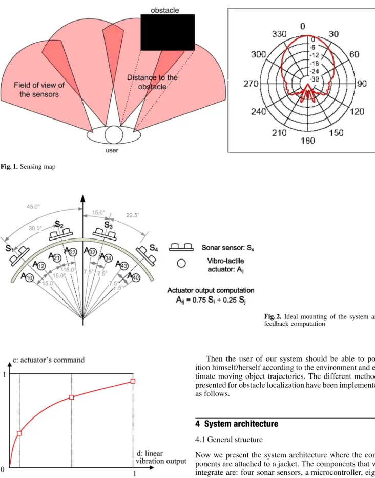
First we determine which direction the obstacles come from. Localization on the horizontal plane is done by the appropriate combination of vibration according to the feedback of the sensors. The sonar modules return the dis-tance of the nearest obstacle in range. Figure 1 shows the sensing abilities given by our system and the exact shape of the field of view of the sonar sensor.
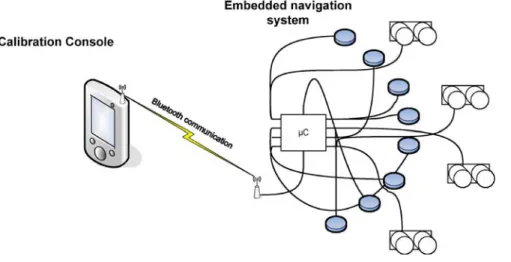
According to the position of the sensors and actuators, the vibrotactile feedback is calculated as shown in Fig. 2. The sonar modules have been placed to cover a large area in front of the user. The overlapping of the sensors’ field of view allows a finer sensing of the environment. The po-sitioning of the actuators has been arbitrarily chosen to be close to the spatial sensitivity of the skin. By using a high linear density of the actuators, we insure a spatial continu-ity of the vibrotactile feedback.
The information to render onto the vibrator is coded as a 200 ms burst of vibration with variable intensity every second. This technique has been used to not overwhelm the user skin and avoid attenuation of his sensitivity to the stimuli resulting from adaptation. In order to normal-ize the rendered vibration according to the variable skin sensitivity of the user, for each vibrator we use a sensitiv-ity curve issued from individual calibration. This curve is a hermit spline used to adjust the user feedback accord-ing to the state of the system. The curve is set usaccord-ing three control points corresponding, respectively, to the detec-tion threshold, an average excitadetec-tion and the maximum intensity as presented in Fig. 3 below. The goal is to in-sure coherent feedback and normalize the response of the actuators.
Moving obstacles can also be localized using the same principles taking in account the user’s own displacement. The user will feel the dynamic changes in the vibrotactile feedback. By these means, he will be able to estimate the position and the speed of the moving object.
Fig. 1. Sensing map
Fig. 2. Ideal mounting of the system and
feedback computation
Fig. 3. Calibration curve
Then the user of our system should be able to pos-ition himself/herself according to the environment and es-timate moving object trajectories. The different methods presented for obstacle localization have been implemented as follows.
4 System architecture
4.1 General structureNow we present the system architecture where the com-ponents are attached to a jacket. The comcom-ponents that we integrate are: four sonar sensors, a microcontroller, eight vibrators and a Pda (personal digital assistant) for the cal-ibration needs (Fig. 4).
Fig. 4. Schema of the system architecture
4.2 Sensors
The sonar system is based on four ultrasonic transduc-ers mounted together. The sensors are fixed at shoulder height to increase obstacle sensing and side determination. Each sensor is equipped with two transducers. One emits an ultrasonic wave while the other measures the echo. By differentiation of the input and output signals, a
micro-Fig. 5. Sonar sensor
Fig. 6. Sonar module timing
di-agram
controller pic16F87 computes the distance to the nearest obstacle. Then this information is transmitted as a PWM signal to the receiver.
We use sonar modules (Fig. 5) designed for robotics and remote controlled unit applications. Such devices are accurate enough for our application with about 1% of error. The range is limited from 3 cm to 3 m in a field of view around 60◦, which perfectly fits our needs. The elec-trical consumption is very low (a few mW), allowing the devices to run for a couple of days on a standard battery supply. The packaging of the transducers is light and small enough(14 × 32 × 8 mm) to be fixed on a jacket without any inconvenience.
The diagram (Fig. 6) above explains the procedure that we followed in order to initiate the sonar sensor and inter-pret its emitted echo pulse signal. Indeed, once the sonar trigger has been fired, it sends eight cycles of sonic burst to the environment. Then, when the echo pulse of the sonic burst comes back to the sonar, the counter’s start value is noted. The counter stops when the echo pulse stops. This distance can then be calculated using the timer’s value.
4.3 Data treatment
Data treatment from the set of sensors is done on an em-bedded 8-bit microcontroller PIC18F6720 [12] (Fig. 8). The microcontroller gathers the information from the ul-trasonic transducers by measuring the width of the echo pulse signal. The pulse width is directly proportional to the distance of the nearest obstacle. By capturing the value of an internal counter 16 bits at rise and fall time of the echo pulse, the microcontroller obtains a 16 bit value of the distance.
Since the microcontroller has 8-bit architecture, for easier calculation we use a mask to recover the eight most significant bits of the distance value. Once this value is re-covered, the output value to be rendered for each actuator is computed according to the different contributions of the sensors (see Fig. 2). The coefficients of 0.75 and 0.25 are very practical in our case, since the computation of the ac-tuator values can be resolved using only bit shifting and addition. Finally, we apply the calibration on each sensor value to compute the final output value of the actuator. This calibration curve takes into account the variation of skin sensitivity and normalizes the vibrotactile response. To compute the final value, we test each control point of the calibration curve and store it into the microcontroller
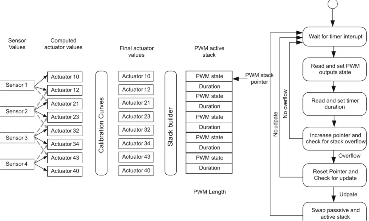
Fig. 7. Embedded software architecture
memory. This curve is composed of eight points that cor-respond to a rasterization of the hermite curve calculated on the calibration device.
When the new actuator values have been computed, the software orders them into a custom PWM stack that concatenates the value of the eight outputs at each times step. The emulation of the PWM output is based on an in-ternal backward counter that can be set and generates an interrupt on reset as shown on Fig. 7. The method used to emulate the different outputs out of a single timer is to compute the different time steps separating each change of the outputs as a whole entity. The software sets the counter to this time step and updates the desired outputs. When the time step is over, the pointer reads the new values on the stack and goes on.
4.4 Actuators
Vibrators are miniaturized continuous current engines with an asymmetric rotor mass. Vibration is created by the rotation of the center of gravity of the mass around the axis of rotation.
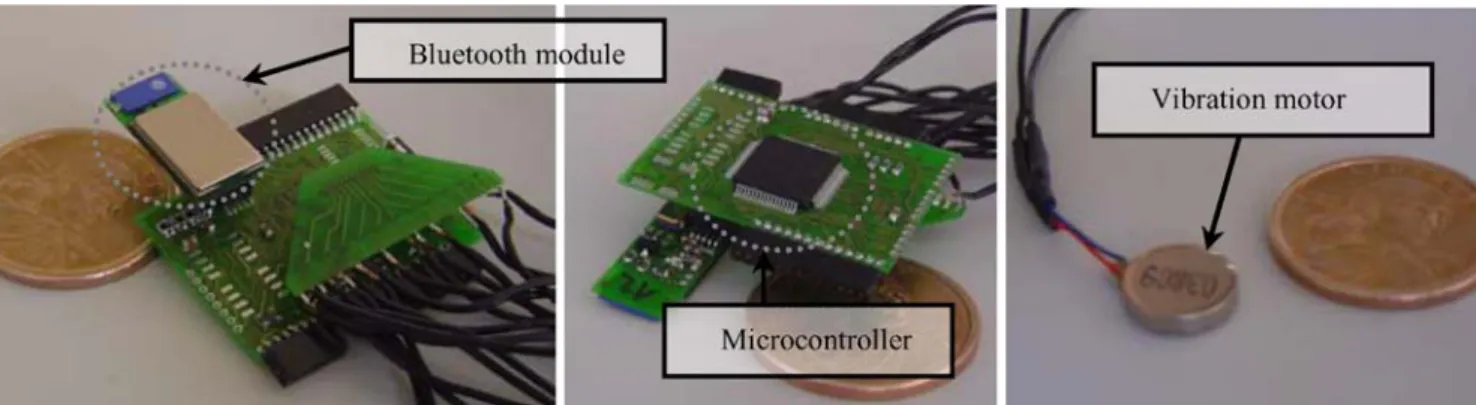
The actuators used to render the tactile information are DC vibration motors issued from the mobile phone technology. For this application, we used the coin motor
Fig. 8. Embedded system
SAM-A300 that allows easy mounting on the user body. By sending PWM input to this simple brushless DC motor we can adapt its speed and then the mechanical vibrating energy to transmit through to the user’s skin. These mo-tors are the size of a coin battery for watches, which allows better integration into clothing. They are also produced in huge amounts so their price is very low.
4.5 Calibration console
The calibration of the actuators needs graphical interface and user input. This calibration device is designed to ad-just the system to the visually impaired user by a third person. The actual interface (see Fig. 9) allows us to select one of the actuators and modify dynamically its calibra-tion curve. While the calibracalibra-tion system is connected we can disable the sonar and send desired outputs on the ac-tuators by triggering the slide bars. This interface has been implemented using the graphical engine Mvisio[26]. This homemade library allows fast programming for 2D and 3D interfaces and can be run on different platforms.
Fig. 9. Calibration console
This part of the software has been implemented on a handheld device to increase the mobility of the sys-tem. This device includes a bluetooth connection that al-lows communication with the embedded microcontroller through a serial interface. Once the calibration curve is edited the user can load it onto the microcontroller mem-ory. This system has been used to increase the perform-ance and the accuracy of the feedback for the tests pre-sented in the next part.
5 Discussion and results
5.1 Test methodologyTo evaluate the system we have developed a small test method. By blind folding the user’s eyes, we simulate the deficiency of the visual system. Then we disorient the user by having him turn around several times. This stops him from memorizing the path through the environment. Then we ask him to navigate through a corridor without using his hands to touch the walls. The user only relies on the system to know at which distance he is from the walls.
For evaluating the dynamic obstacle avoidance, we use other people walking toward the user and doors opening or closing. This simulation is designed to be close to the real application conditions. To stop the user from detecting moving obstacles by hearing them, he is equipped with ear plugs.
The evaluation is made by an outside person who judges the performance of the user by measuring the time he takes to pass through the corridor, measuring his im-provement due to training and seeing whether the user encounters collisions with the environment.
5.2 Results
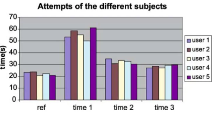
These results were obtained by using the same tests on five different users. On the graph shown in Fig. 10 we meas-ure the time of each user on their attempts. The reference
Fig. 10. Results of the validation test
time on the first column represents the time taken to pass through the corridor in a normal condition. The other three represent the successive performances of each user blind-folded and equipped with our system.
The results show that our system is quite intuitive, since we can observe a reduction of 50% of the time to pass through the obstacles after a couple of minutes train-ing with the system. The time to pass through the corridor is still a bit higher than with the full use of sight. This phenomenon can be explained by the limited confidence of the user in the system. The users sensed other people walking and avoiding them in the corridor. They had de-termined correctly on which side they were passed by. 5.3 Discussion
The results of the experience are very encouraging. The equipped user is able to walk through the corridor in a rea-sonable time after a bit of training. The collisions are perfectly avoided and the user is able to distinguish an ob-stacle from its left and right and to localize himself in his environment. It provides reliable feedback about the sur-rounding environment by vibrotactile mapping. The com-bined motion of the user and a moving obstacle provide an accurate perception of its trajectory.
The users trained very fast with the system and man-aged to navigate indoors easily after several minutes. Those results demonstrate that our system is intuitive and easy to use. The oral informal feedback of the subjects making those attempts was that once the discovery time phase passed, the system provided accurate information about the surrounding environment.
One aspect that reduces the performance of the sys-tem is the difference of the ultrasonic reflectance of the different materials that constitute our environment. This difference alters the reliability of the sonar sensor and can lead to some anomaly in the vibrotactile feedback.
Another disturbing phenomenon comes from the oc-clusion of the sensor by the user’s hands. It becomes a real threshold for its usability at close range, because the nat-ural reaction when approaching an obstacle is to interpose the hand.
Except for those two minor artifacts, we were very pleased with the behavior of the system in those prelim-inary tests. The system demonstrates itself to be reliable, intuitive and accurate.
6 Conclusion
The system is hardwired from the sensors to the actua-tors via the microcontroller. Each part of the system is also mounted on a hard circuit board. It will be interesting to directly weave the wires inside the textile fiber and to use a semi-rigid support for the mounting of the electronic com-ponents inside the vest.
Another solution to improve the wearable aspect could be to design the system as a set of independent modules that can be fixed on the cloth and communicate via a wireless connection. In order to accomplish a perfectly wearable system, the miniaturization should be improved on the sensors and the actuators. Those will not be, in the close future, perfectly wearable but may approximate the size of a standard button or clipper present on the most common vest.
The actual mapping is mainly based in the horizontal plane. It would be interesting in a further development to map a 3D environment. One way would be to detect the position of an obstacle and give feedback to the user concerning its height. This is a necessary step before re-moving totally the use of the white cane, since at this stage our system is not be efficient for walking up or down stairs, for example.
The last aspect to be improved will be to change the nature of the sensor. This is due to the sensitivity of the ultrasonic sensor to the surface properties of the de-tected material. One interesting technology will be to use a stereoscopic camera system and vision algorithm to gather depth information. As said in the state-of-the-art, those methods are not perfectly reliable for every kind of envi-ronment and can fail according to the surrounding light-ing. However, correlation of different technologies would be interesting to study.
In order to properly optimize our system, it will be im-portant to test and adjust it with a representative amount of visually impaired users. This is important to measure the benefit given by this system in addition to the traditional white cane.
However, with maximum power consumption below the watt, our system can run for hours from of a single battery supply. By its multi-sensor architecture, it allows positioning by telling the user from which side an obstacle is coming. Each part is small enough to be fixed on cloth, which ensures that the whole system is wearable. It also lets the user have his hands free for other purposes. This device has taken us a step forward in the integration of vi-sually impaired people and is a precious help when vision is reduced by a harsh environment. The current system
still needs some small improvements before it is a per-fect fit to the application but it demonstrates its usability perfectly.
Acknowledgement We would like to thank Xavier Righetti,
Mas-ter’s student, who produced remarkable work on the development
of this application. Also we would like to acknowledge the excel-lent graphic tools represented by the Mvisio library developed in our laboratory by Achille Peternier. We are also grateful to Jean-Christophe Zufferey and Dario Floreano, from the Laboratory of Intelligent Systems, who provided us with the microcontroller’s layout and the bluetooth communication module.
References
1. Benjamin, J.M., Ali, N.A., Schepis, A.F.: A laser cane for the blind. In: Proceedings of the San Diego Biomedical Symposium, vol. 12, pp. 53–57 (1973)
2. Craig, J.C.: Difference threshold for intensity of tactile stimuli. Percep. Psychophys. 11, 150–152 (1972) 3. Craig, J.C., Evans, P.M.: Vibrotactile
masking and the persistence of tactual features. Percept. Psychophys. 42, 309–317 (1987)
4. Espinosa, M.A., Ungar, S., Ocha´ıta, E., Blades, M.: Comparing methods for introducing blind and visually impaired people to unfamiliar urban environments. J. Environ. Psychol. 18, 277–287 (1998) 5. Gescheider, G.A.: Temporal relations in
cutaneous stimulation. In: Geldard, F.A. (ed.): Cutaneous communication systems and devices. The Psychonimic Society, Austin, TX (1974)
6. Goff, G.D.: Differential discrimination of frequency of cutaneous mechanical vibration. J. Experiment. Psychol. 74, 294–299 (1967)
7. Gallace, A., Tan, H.Z., Spence, C.: Tactile change detection. In: Proceedings of the First Joint Eurohaptics Conference and Symposium on Haptic interfaces For Virtual Environment and Teleoperator Systems (March 18–20, 2005) (WHC’05), pp. 12–16. IEEE Computer Society, Washington, D.C. (2005)
8. Hahn, J.F.: Vibrotactile adaptation and recovery measured by two methods. J. Experiment. Psychol. 71, 655–658 (1966) 9. Hahn, J.F.: Vibrotactile adaptation and
recovery measured by two methods. J. Experiment. Psychol. 71, 655–658 (1966)
10. Hillstrom, A.P., Shapiro, K., Spence, C.: Attentional and perceptual limitations in
processing sequentially presented vibrotactile targets. Percept. Psychophys.
64, 1068–1082 (2002)
11. Ito, K., Okamoto, M., Akita, J.: CyARM: an alternative aid device for blind persons. CHI ’05 Extended Abstracts on Human Factors in Computing Systems (Portland, OR, USA, April 02–07, 2005) (CHI ’05), pp. 1483–1488. IEEE Computer Society (2005)
12. Microchip, http://www.microchip.com 13. Panuccio, A.: A multimodal electronic
travel aid device. In: Proceedings of the 4th IEEE International Conference on Multimodal Interfaces (ICMI 02), p. 39. IEEE Computer Society, Washington DC (2002)
14. Rupert, A.H., McGrath, B.J., Griffin, M.: A tool to maintain spatial orientation and situation awareness for operators of manned and unmanned aerial vehicles and other military motion platforms. RTO HFM Symposium on “Spatial Disorientation in Military Vehicles: Causes, Consequences and Cures”, 31.1–31.15, National Technical Information Service, Springfield, VA (2002) 15. Schmidt, R.F.: Fundamentals of Sensory
Physiology. Springer, Berlin Heidelberg New York (1979)
16. Strothotte, T., Fritz, S.: Development of dialogue systems for a mobility aid for blind people: initial design and usability testing. In: Proceedings of the Second Annual ACM Conference on Assistive Technologies (Vancouver, B.C., Canada, April 11–12, 1996). Assets ’96, pp. 139–144. ACM Press, New York (1996)
17. The life of a guide dog, www.guidedogs.co.uk
18. UltracaneTM, www.soundforesight.co.uk
19. van Erp, J.B.F: Guidelines for the use of vibrotactile displays in human computer interaction. In: S.A. Wall et al. (eds.) Proc. of Eurohaptics 2002, pp. 18–22. University of Edinburgh, Scotland (2002)
20. van Erp, J.B.F., van Veen, H.A.A.C.: A multipurpose tactile vest for astronauts in the international space station. In: Proceedings of EuroHaptics ’03, pp. 405–408. Trinity College, Dublin, Ireland (2003)
21. van Erp, J., van Veen, H., Janseen, C., Dobbins, T.: Vibrotactile waypoint navigation at sea and in the air: two case study. In: Proceedings of EuroHaptics ’04, ACM Trans. Appl. Perception, pp. 166–173 (2005)
22. van Erp, J.B.F.: Vibrotactile spatial acuity on the torso: effects of location and timing parameters. In: Proceedings of the First Joint Eurohaptics Conference and Symposium on Haptic Interfaces for Virtual Environment and Teleoperator Systems (March 18–20, 2005) (WHC’05), pp. 80–85. IEEE Computer Society, Washington, D.C. (2005)
23. Verrillo, R.T.: Temporal summation in vibrotactile sensitivity. J. Acoust. Soc. Am.
37, 843–846 (1965)
24. Wexler, M., Panerai, F., Lamouret, I., Droulez, J.: Self-motion and the perception of stationary objects. Nature 409, 85–88 (2001)
25. Yang, U., Jang, Y., Kim, G.J.: Designing a vibrotactile wear for “close range” interaction for VR-based motion training. In: Proceedings of the 12th International Conference on Artificial Reality and Telexistence (ICAT 2002), pp. 4–9 (2002) 26. 3D Mental Vision project,
CARDINSYLVAINreceived his MS in Com-puter Science in 2005 from the Universit´e de la M´editerran´ee. His main work is research on pseudo haptic clothing, including multi-modal sensors and actuators.
DANIELTHALMANNis a pioneer in research on virtual humans. His current research in-terests include real-time virtual humans in virtual reality, immersive virtual environments, crowd simulation, and multimodal interac-tion. Daniel Thalmann has been a professor at The University of Montreal and a visiting professor/researcher at CERN, the University of Nebraska, the University of Tokyo, and the Institute of System Sciences in Singapore. Daniel Thalmann received his PhD in Computer Science in 1977 from the University of Geneva and an Honorary Doctorate (Honoris Causa) from University Paul-Sabatier in Toulouse, France, in 2003. Daniel Thalmann has published more than 400 papers in graphics, animation, and virtual reality. He is coeditor of 30 books, including the recent “Handbook of Virtual Humans”, published by John Wiley and Sons and coauthor of several books. He was also codirector of several computer-generated films with virtual actors including a virtual Marilyn shown on numerous TV channels all over the world. He is Co-Editor-in-Chief of the Journal of Computer Animation and Virtual Worlds, Editor of The Visual Computer, Journal of Uni-versal Computer Science, Computer Graphics & Geometry, International Journal of Human Factors Modelling and Simulation, President of SARIT, the Swiss Association for Research in Information Technology, and Member of the Board of Directors of ERCIM, the Euro-pean Research Consortium for Informatics and Mathematics.
FR ´ED ´ERICVEXOreceived his PhD in Computer Science in 2000 from the Univer-sity of Reims and his Bachelor’s and Master’s degrees from the University of METZ. He has also contributed to various European projects. His research interests are multidisciplinary and include human to inhabited virtual world, haptic interfaces, tele operated systems, multi-modal adaptive interface for virtual worlds, semantic virtual environment and new services for graphic mobile devices. He is author of several papers in journals and inter-national conferences in the fields of human computer interaction, robotics and computer graphics. He is a member of several conference program committees and an expert for different institutions and companies.