Computer-Aided Design for Multilayer
Microfluidic Chips
Ot
T
,
rrUTby
JUL 2
0
Nada Amin
LIBRARIES
Submitted to the Department of Electrical Engineering and Computer
Science
in partial fulfillment of the requirements for the degree of
Master of Engineering in Computer Science and Engineering
at the
MASSACHUSETTS INSTITUTE OF TECHNOLOGY
February 2009
©
Massachusetts Institute of Technology 2009. All rights reserved.
A uthor ...
Department of Electrical Engineering and Computer Science
Decemler 12, 2008
Certified by ... ...Saman P. Amarasinghe
Associate Professor
Thesis Supervisor
Accepted by... LArthur C. Smith
Chairman, Department Committee on Graduate Theses
X,
'111'_-'._'_"
?11
.
- _' 111,"lComputer-Aided Design for Multilayer Microfluidic Chips
by
Nada Amin
Submitted to the Department of Electrical Engineering and Computer Science on December 12, 2008, in partial fulfillment of the
requirements for the degree of
Master of Engineering in Computer Science and Engineering
Abstract
Microfluidic chips fabricated by multilayer soft lithography are emerging as "lab-on-a-chip" systems that can automate biological experiments. As we are able to build more complex microfluidic chips with thousands of components, it becomes possible to build devices which can be programmatically changed to solve multiple problems. However, the current design methodology does not scale. In this thesis, we introduce design automation techniques to multilayer soft lithography microfluidics. Our work focuses on automating the design of the control layer. We present a method to define an Instruction Set Architecture as a hierarchical composition of flows. From this specification, we automatically infer and generate the logic and signals to control the chip. To complete the design automation of the control layer, we suggest a routing algorithm to connect control channels to peripheral I/O ports. To the microfluidic community, we offer a free computer-aided design tool, Micado, which implements our ideas for automation in a practical plug-in to AutoCAD. We have evaluated our work on real chips and our tool has been used successfully by microfluidic designers. Thesis Supervisor: Saman P. Amarasinghe
Acknowledgments
I thank Professor Saman Amarasinghe for supervising this research.
I thank David Craig, Moeto Nagai J.P. Urbanksi and their supervisor Professor Todd Thorsen for providing essential feedback as designers of microfluidic chips. I also thank Professor Stephen Quake and Dr. Jessica Melin for discussions, feedback, sharing designs and an opportunity to share our tool with the broader community.
I thank Bill Thies for mentoring me in this research. Bill introduced me to the field of programmable microfluidics and its opportunities for design automation. He met weekly with me to discuss my progress and brainstorm ideas. Except for the actual implementation, he has contributed significantly to all aspects of this work.
Contents
1 Introduction 15
2 Multilayer Microfluidic Chips 19
3 Motivating Example 23
4 Specifying a Microfluidic ISA 29
4.1 Flow Annotations ... 29
4.1.1 Example ... ... 29
4.1.2 Commands ... ... 30
5 Generating Control Logic 33 5.1 Generation of Control Components . ... 33
5.1.1 Problem Definition ... ... 33
5.1.2 Complexity of Control Minimization . ... 33
5.1.3 Practical Solution ... ... 34
5.2 Generation of Control Program ... .. . . 37
6 Routing Control Channels 39 6.1 Problem Definition ... ... . 40
6.2 Algorithm ... ... .. 42
6.3 Analysis ... ... 43
8 Evaluation
9 Related Prior Work 57
9.1 CAD for Microfluidics ... ... 57 9.2 CAD for Electronics ... ... 57 9.2.1 Differences between electronic CAD and microfluidic CAD . . 58 9.3 Abstractions for Microfluidics ... ... 59
List of Figures
2-1 Layout of a microfluidic chip. ... ... 20
2-2 Photo of a microfluidic chip. . ... .... 20
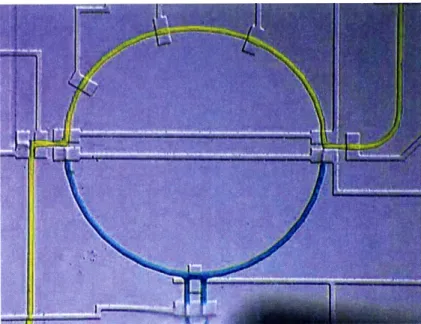
2-3 Photo of part of a real chip with two different fluids ready to be mixed. 21
2-4 Photo of a real chip in action. ... ... 21
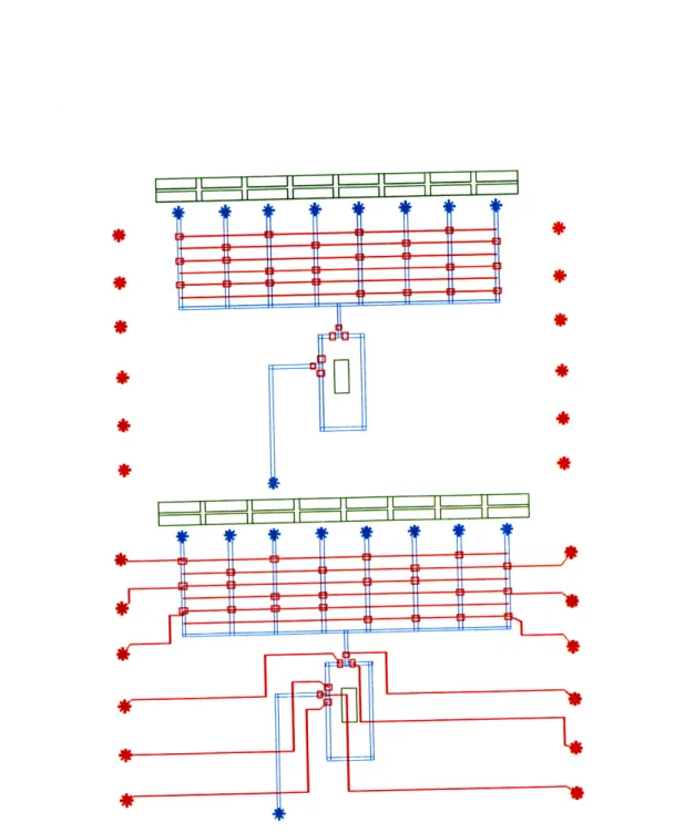
3-1 The flow layer manually designed (top). The primitive flow annotations required to hierarchically annotate the flow (bottom). . ... 24
3-2 The control components (in red) and buttons (in green) automatically generated. The buttons (in green) were generated at the user's request for the end-to-end s and mixing flow annotations (top). One particular button has been clicked, its flow highlighted (in black), triggering the opening and closing of valves (in blue and red, respectively) (bottom). 26
3-3 The punches manually placed (top). The automatic routing between control channels and punches respecting design constraints (bottom). 27
4-1 A simple flow layer, which we will annotate to express all flow manipu-lations from any inputs (al, a2, a3, a4) to output (c) via either any one
5-1 The flow has been annotated with all manipulations from any of the 8 inputs to any of the 2 outputs (c1, C2) via bl, b2 or both, concisely
as in Section 4.1.1. The control inference (in red) was automatically inferred and generated from the annotations. The buttons on the left correspond to flow manipulations. Each input has 6 possible manipu-lations, because there are 2 kinds of outputs (buttons filled in gold for
c1, in yellow for c2) and 3 kinds of intermediaries (buttons outlined in
dark green for bl, light green for b2 and intermediary green for both).
A particular flow manipulation is highlighted (in black). The dotted red lines indicates additional grouping of valves that the annotations
allow but our inference heuristics don't exploit. . ... . 34 6-1 A simple routing problem and solution. The superposition of the
con-crete problem, in terms of control and flow layers, and the abstract problem, in terms of a routing graph, illustrates the straightforward map from one to the other ... ... . 42 6-2 Routing of a chip after min-cost max-flow step (top) and after one
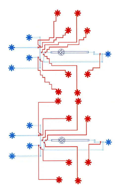
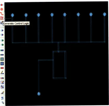
iteration of ripping and redoing each connection (bottom). ... . 45 7-1 Micado screenshot. The flow has been drawn manually and annotated
graphically. The user is about to click the button to generate the control logic ... ... ... ... ... 48 7-2 Micado screenshot. The control components were automatically
gen-erated by a single user click. The user added each control punch by a single click at their center. The user is about to click the button to connect control channels to control punches. . ... . . 48 7-3 Micado screenshot. The control layer is complete. The user created two
rectangles as place-holders for the flow manipulation buttons, which were automatically generated at his request. The user is about to click the button to export the drawing to a programmable GUI. ... . 49 7-4 Screenshot of a programmable GUI generated by Micado ... 49
8-1 Cell culture chip with 1 chamber before (top) and after (bottom) au-tomatic routing by single-clicking. ... . 53 8-2 Chemical waveform generator chip with 16 chambers before (top) and
after (bottom) automatic routing by single-clicking. . ... 54 8-3 Metabolite detector chip before (top) and after (bottom) automatic
routing by single-clicking . ... ... . 55 8-4 Example of generated visual tool for controlling chip, before (top) and
after (bottom) single-clicking on an instruction, which opens a flow path from an input to the chamber. The open valves are in blue, the closed valves in red. ... ... ... .... . 56
List of Tables
6.1 Design constraints for routing. ... ... ... 40 7.1 Setting parameters for Micado. ... .. 50 8.1 Summary of the features of the real chips evaluated and presented. 51
Chapter 1
Introduction
Programmable microfluidic chips are "lab-on-a-chip" systems, that can automate bi-ological computations or experiments by integrating a diverse set of bibi-ological sensors and by manipulating fluids at the picoliter scale [37, 11, 13, 14, 19, 20, 25, 34, 35, 36, 5, 10, 24]. Multilayer soft lithography [30] is a popular fabrication process for microfluidics. Soft-lithography chips are a good match for "continuous-flow" experi-ments in which a single fluid permeates the device. They have also been adapted to perform "digital" microfluidics, in which individual fluid samples are suspended in a background phase and manipulated independently [31]. Another approach to digital microfluidics is to manipulate independent droplets on an electrode array [22, 7]. As discussed in Section 9.1, prior work in microfluidic CAD [4, 6, 28] targets droplet processors rather than multilayer soft lithography as we do.
As we are able to build more complex microfluidic chips with thousands of compo-nents [21, 15], it becomes possible to build general purpose or programmable devices which can be programmatically changed to solve multiple problems [31]. However, the current design methodology relies on many manual steps and represents a serious barrier to scaling the design complexity to the limits allowed by the underlying tech-nology. Chips are usually designed by drawing in AutoCAD, with control placement and routing done by hand; the control logic is manually orchestrated to accomplish needed tasks on chip; and graphical users interfaces (GUIs) are re-constructed in a separate program (LabView) that is disconnected from chip layout. This current
method of manual design does not scale and is very brittle to design changes, e.g. adding a few valves entails redoing the whole routing and whole GUI. Thus, the in-creasing complexity of microfluidic chips drives the need for automated design tools. We aim to bring the same automation and discipline to microfluidic design that electronic CAD brought to circuit design. Such automation was the key to designing the billion-transistor chips that power all of today's infrastructure. As a first step in this direction, we focus on automating the design of the control layer in this thesis. Indeed, while flow channels have many application-specific subtleties for each chip, the control has many valid solutions while still being subject to rigorous constraints, and also being tedious to do by hand. We make the following contributions:
1. Adaptation of a routing algorithm to connect peripheral I/O ports (punches) to internal control elements (valves) within design constraints.
2. Specification of the tasks the user wants to do, similar to how microprocessors are programmed with an Instruction Set Architecture (ISA), as a hierarchical composition of flows.
3. Inference of control logic from the specification.
4. Generation of control signals and programmable GUI from the specification.
5. Micado, a working implementation supporting iterative design, as a plug-in to AutoCAD used by designers of microfluidic chips.
6. Experimental evaluation on real chips, demonstrating the usefulness of our au-tomation in practice.
The thesis is organized as follows. We review multilayer soft lithography chips in Section 2. We motivate our automation techniques with an end-to-end example in Section 3. We introduce flow annotations for specifying ISAs in Section 4. We cover generation of control logic, both components and programs, from flow annotations in Section 5. We define the problem of routing control channels and propose a tractable
and practical solution in 6. We describe Micado, a free software that plugs into Au-toCAD, which implements our work in Section 7. We evaluate our work in Section 8. We review related work in Section 9. We conclude in Section 10.
Chapter 2
Multilayer Microfluidic Chips
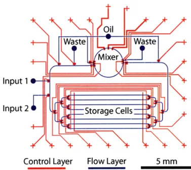
Our work targets the design of microfluidic chips fabricated by multilayer soft lithog-raphy [30, 9]. Soft lithography is a microfabrication process, in which a soft polymer (e.g. polydimethylsiloxane (PDMS)) is cast onto a mold containing an engraved pat-tern. In multilayer soft lithography, devices typically have two elastomer layers. The flow layer contains channels for flowing fluids of interest, while the control layer con-tains channels for control signals. Where the flow channel intersects a thick control channel, a valve is formed. When the control channel is pressurized, the valve de-flects into the flow channel, stopping the flow of fluid. Thus, by pressurizing and depressurizing the channels, the flow of fluid can be controlled.
Figure 2-1 shows the layout of a microfluidic chip. Figure 2-2 is a snapshot of part of this chip, once fabricated. Figure 2-3 is a snapshot of part of the chip with two different fluids ready to be mixed. Figure 2-4 is a snapshot of a real chip in action.
Designing a microfluidic chip involves integrating a diverse set of components. The two main simple components are punches and valves. A punch is an endpoint of a channel, in which an external fluid line is inserted to feed or control the chip. A valve is a large intersection where a control channel crosses a flow channel, enabling control of the flow of fluid. Components in microfluidic large scale integration [21] include peristaltic pumps, multiplexers and storage cells. A peristaltic pump is composed of three or more pumps in series, activated sequentially, enabling active displacement, mixing or measuring of the fluid.
Input 1
Input 2
Control Layer Flow Layer
Figure 2-1: Layout of a microfluidic chip.
Figure 2-2: Photo of a microfluidic chip.
Figure 2-3: Photo of part of a real chip with two different fluids ready to be mixed.
The development of microfluidic devices with thousands of integrated microme-chanical valves and control components needs design automation tools and abstrac-tions to remain tractable at a large scale.
Chapter 3
Motivating Example
In order to illustrate our ideas for design automation of microfluidic chips, we show how to design a chip to mix a sample of metabolites from a cell with an indicator in a specific ration.
The chip has 8 input flow punches, which can contain either the cell sample or the indicator. These input punches are connected to a mixer. The mixer is connected to an output punch, in such a way that it is composed of two uneven paths: the ratio of one path to another determines the built-in mixing ration.
The control should be able to move a sample or indicator from any of the input punches to one of the two mixing paths. When both mixing paths are filled, the mixer can mix the fluids around the mixing path. Finally, after the mixed fluid has been analyzed, it can be drained to the output punch.
First, we manually design the flow layer of the chip, as shown in Figure 3-1. Second, we annotate the flow to express the manipulations of the chip. We want to move a sample or indicator from any of the input punches (al,..., as) to the output punch (c) via either the short left mixing path (b1) or the long right mixing path (b2).
While these annotations can easily be expressed graphically using our tool, we write them in text format in this thesis. We express all these manipulations by composing flow annotations hierarchically as follows:
all~ atfllt~ a,
ll~abl a-:Dlk
Q01-- b2
-
h2
C*
Figure 3-1: The flow layer manually designed (top). The primitive flow annotations required to hierarchically annotate the flow (bottom).
b = ORx-(bl, b2) The flow from x to y, through either bl or b2.
s = SEQ(a, b, c) The flow from any input to c via either b, or b2.
Once we move in a sample and an indicator, we would like to mix them together along the mixing path. We express mixing simply as MIX(x, b2, bl). The MIX
shortcut command creates a circular pumping annotation. Section 4 describes flow annotations in more details.
Third, we automatically infer and generate the control logic to execute the instruc-tions entailed by the flow annotainstruc-tions. We also generate buttons for the end-to-end flow annotations. Buttons are not fabricated on the device, but are exported as part of the graphical user interface. Users click on a button to elicit a given flow pattern. Figure 3-2shows the control components and buttons generated for the chip. Section 5 explains the generation of control and GUI components.
Fourth, we manually place control punches and automatically route the control channels to the punches. Figure 3-3shows the chip after routing. Section 6 describes routing.
I
Figure 3-2: The control components (in red) and buttons (in green) automatically generated. The buttons (in green) were generated at the user's request for the end-to-end s and mixing flow annotations (top). One particular button has been clicked, its flow highlighted (in black), triggering the opening and closing of valves (in blue and red, respectively) (bottom).
I .I II I I Ii II I I I
~ILL J LJ~-I LJ-LI ' I
I II II II II II ==
L1~ -- m ii n1J ii ii n~
Figure 3-3: The punches manually placed (top). The automatic routing between control channels and punches respecting design constraints (bottom).
Chapter 4
Specifying a Microfluidic ISA
Previous research has established the notion of a Microfluidic ISA as the primitive set of operations supported by a microfluidic device [29, 2]. While ISA's for electronic chips are difficult to specify graphically (as the 32-bit logical operations are difficult to visualize), with microfluidics the instructions represent logical flows that can be hierarchically constructed. We provide the first method to define an ISA as a hier-archical composition of flows, allowing scalability across parameterized numbers of inputs, outputs, and cells.
4.1
Flow Annotations
Flow annotations express the flow manipulations independently of control signals. This way, the designer focuses on the manipulations of the flow in his chip, without worrying about the details of the control required to support such manipulations.
4.1.1
Example
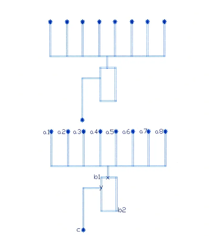
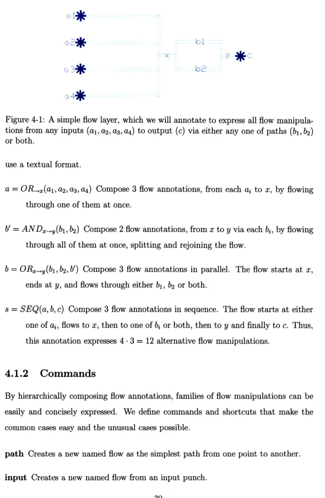
As an introductory example, Figure 4-1 shows a simple flow layer annotated with primitive inputs (al, a2, a3, a4), output (c), paths (bl, b2) and points (x, y). By
com-posing these annotations, we can express useful flow manipulations concisely. Our tool allows the user to construct these annotations graphically, but in this thesis we
0
1*
Figure 4-1: A simple flow layer, which we will annotate to express all flow manipula-tions from any inputs (al, a2, a3, a4) to output (c) via either any one of paths (b1, b2)
or both.
use a textual format.
a = ORX(al, a2, a3, a4) Compose 3 flow annotations, from each ai to x, by flowing
through one of them at once.
b' = ANDx-.,(bl, b2) Compose 2 flow annotations, from x to y via each bi, by flowing
through all of them at once, splitting and rejoining the flow.
b = ORxy(bl, b2, b') Compose 3 flow annotations in parallel. The flow starts at x,
ends at y, and flows through either bl, b2 or both.
s = SEQ(a, b, c) Compose 3 flow annotations in sequence. The flow starts at either
one of ai, flows to x, then to one of bi or both, then to y and finally to c. Thus, this annotation expresses 4 -3 = 12 alternative flow manipulations.
4.1.2
Commands
By hierarchically composing flow annotations, families of flow manipulations can be easily and concisely expressed. We define commands and shortcuts that make the common cases easy and the unusual cases possible.
path Creates a new named flow as the simplest path from one point to another. input Creates a new named flow from an input punch.
output Creates a new named flow from an output punch.
or Creates a new named flow as some exclusive combination of other named flows, also specifying where the parallel flows meet if applicable. The flow will remain unsplit and progress down only one channel, depending on which option the user has selected. Note that if many OR blocks are composed sequentially, then there is a combinatorial explosion of the number of options presented to the user.
and Creates a new named flow by splitting and joining parallel named flows, also specifying the split and join points if applicable. The flow will split into many branches and be active in all channels at once.
seq Creates a new named flow by composing other named flow in sequence, complet-ing the flow path as simply as possible between successive named flows in the sequence.
pump Creates a new named flow by pumping along another named flow. The flow will be actively pumped instead of passively let through. Thanks to hierarchical composition, it is perfectly possible to annotate a composed flow with both pumping and non-pumping parts.
In addition, we define some shortcuts for convenience. These convenience com-mands aren't essential, as they can be constructed from the other comcom-mands.
or-inputs Creates a new named flow as an exclusive combination of input punches, without having to name all the punches individually.
or-outputs Creates a new named flow as an exclusive combination of output punches, without having to name all the punches individually.
Chapter 5
Generating Control Logic
We describe the first method to automatically generate the control logic and signals needed to implement the defined ISA. The drawing and control signals can be exported into a programmable graphical user interface for controlling the chip and running experiments. Our method relieves the user from a tedious and error-prone manual process, which had to be repeated with each design revision. Our method also possibly minimizes the number of control channels better than the user could manually.
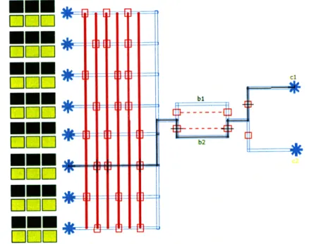
Figure 5-1 illustrates the generation of control components and the correspondence between flows and buttons in the graphical user interface.
5.1
Generation of Control Components
5.1.1
Problem Definition
We describe the problem of generation of control logic in Problem Definition 1.
5.1.2
Complexity of Control Minimization
The general problem of minimizing control channels given patterns of valve activation (for each flow annotation, each valve can either be open or closed) is NP-hard, even ignoring routing feasibility and valves conditionally opened or closed. Indeed, we can reduce graph coloring, an NP-complete problem [16], to control minimization by
M
Mmm
000]
F-TIF-4I
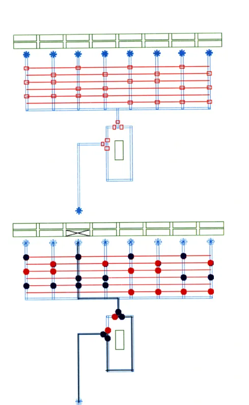
Figure 5-1: The flow has been annotated with all manipulations from any of the 8 inputs to any of the 2 outputs (Cl, c2) via bl, b2 or both, concisely as in Section 4.1.1.
The control inference (in red) was automatically inferred and generated from the an-notations. The buttons on the left correspond to flow manipulations. Each input has 6 possible manipulations, because there are 2 kinds of outputs (buttons filled in gold for cl, in yellow for c2) and 3 kinds of intermediaries (buttons outlined in dark green
for bl, light green for b2 and intermediary green for both). A particular flow
manipu-lation is highlighted (in black). The dotted red lines indicates additional grouping of valves that the annotations allow but our inference heuristics don't exploit.
mapping each vertex to a valve and each edge to an open/close conflict. Solving the reduced problem optimally gives a smallest set of control channels. We can then solve the original graph coloring problem optimally by coloring vertices with the same color if their corresponding valves belong to the same control channel.
5.1.3
Practical Solution
We present a set of heuristics for generating control logic for each flow annotation from input to output (complete flow), while attempting to minimize the number of valves needed. Our heuristics rely on the flow annotations for guidance. From our experience, valves sharing is most beneficial when a set of inputs/outputs need to be selected individually, in which case a multiplexer is appropriate. Thus, we use the
~~tS~
C1
bl
b2
Problem Definition 1 Generation of Control Logic Given
* the flow layer (expressing the chip connectivity), * the flow annotations (expressing the desired flows
active at once), produce:
* control valves on top of the flow layer,
* sharing of which valves can have same control chan-nel while respecting routing feasibility,
* internal table of which valves should be activated for given flow,
while minimizing the number of control channels.
or-flows to guide the generation of multiplexers and then use the complete flows to guide the generation of other needed valves.
The or-flows guide the generation of multiplexers. Multiplexers are only generated if there are at least 4 options and if there is enough space, and, to support iterative development, if the flow segments under consideration are free of designed valves, i.e. valves already on the chip before the inference routine.
The complete flows guide the generation of single valves. As a first approximation, valves are inferred to block flow in paths not taken after a juncture. Algorithm 1 de-tails the procedure for inferring single valves and calculating their activation pattern. In certain circumstances it is desirable to have a looser model that removes re-dundant valves. Usually, control is strict to ensure there is no contamination across channels. However, long-running flows that flush out any contaminants at the start of execution can tolerate a loose model, where active flows do not make any progress down paths that are later blocked. We avoid redundancy in two ways. To avoid redundancy between inferred valves and multiplexers, or-flows for which multiplex-ers were previously inferred are temporarily replaced with and-flows before calling Algorithm 1. To avoid even more redundancy, we use Algorithm 2.
Algorithm 1 Calculate inferred valves and their activation state per manipulation given a list of expanded complete flow manipulations. A valve is inferred to block flow on an edge through one of its endpoints, thus its position is abstractly recorded by a pair of a node and an edge. In the "for ... yield" construct, the results returned by "yield" are accumulated.
let calculate (ms : Array<Manipulation>) =
let inferValvesFor (m : Manipulation) =
for e in used edges of m for n in endpoints of e
for e' in edges neighboring e via node n if e' not in used edges of m
then yield (n,e') let allInferredValves =
union (inferValvesFor m for each m in ms) let activationState (n,e) m =
if (n,e) in (inferValvesFor m) then closed
else if e in used edges of m then open
else don't care
allInferredValves, activationState
Algorithm 2 Determine whether a valve inferred on edge e, adjacent to node n, can be safely removed while still implementing all the manipulations ms. Assumes a loose model of flow control, where active flows do not make any progress down paths that are later blocked. To ensure correctness, note that this algorithm ignores multiplexers, because they share control across many valves.
let redundantValve ms (n,e) : bool = let wet (e' : edge) : bool =
exists m in ms s.t.
e' in used edges of m and (activationState (n,e) m) = closed let blocked (e' : edge) : bool =
e' contains a valve with a dedicated control line
//
A valve is redundant if all paths to wet flows contain a blocked edge.forall acyclic paths (n, e, n_l, e_l1, ..., n_k, e_k) s.t. wet(ek): exists e' in (e, e_l1, ..., e k) s.t. blocked(e')
In summary, our overall solution
1. infers multiplexers guided by the or-flows,
2. infers single valves needed to perform all complete flow manipulations (Algo-rithm 1) temporarily replacing each or-flow for which a multiplexer was previ-ously inferred with an and-flow,
3. (optionally) filters out the inferred single valves deemed redundant with respect to other single valves under the loose model (Algorithm 2).
The solution may not eliminate all redundant valves with respect to the multiplex-ers. For example, if a multiplexer is inferred for some inputs 1... n and a separate complete flow manipulation singles out one of these inputs, then the second step in-fers additional valves to isolate the singled-out input, even though the multiplexer is sufficient. The optional third step would detect this redundancy if Algorithm 2 was changed to also consider multiplexer valves (in the definition of blocked), but then, the solution would not be guaranteed correct. Indeed, as Algorithm 2 is evaluating the redundancy of a single valve that can be independently toggled, only valves that are unshared and have complete freedom can block a channel to the same effect.
Control generation and minimization offers many opportunities for future work. In particular, we could reduce the number of control channels beyond multiplexing by grouping valves that are always activated together in each flow manipulation. Figure 5-1 shows in red dotted lines an example of possible additional grouping of valves that our current heuristics don't exploit yet. Furthermore, we need to take pumping annotations into account during control generation, as those annotations might require additional valves to execute properly.
5.2
Generation of Control Program
The annotated chip design can be exported into a programmable graphical interface for controlling the chip.
The user selects flow annotations, typically those mapping to end-to-end manip-ulations, for which to generate buttons and callable methods in the programmable graphical interface. When a user decides to generate buttons for a flow annotation, the or-flows within it are expanded so that it intuitively maps to an array of simple flow manipulations, one for each combination of options.
The control signals are automatically inferred from the annotations. For a given flow manipulation, they indicate which valves should be open and closed, and, if pumping, in what order.
Chapter 6
Routing Control Channels
The routing process is one of the most tedious and constrained in the design of microfluidic chips. Yet it is also one of the most flexible, in that different solutions are valid so long as they satisfy constraints. Hence, it is a rich target for automation. We automate the routing of valves to punches in the control layer. The control layer is composed of separate control channels, each of which interconnects a punch and valves which open and close in unison. We propose an algorithm to connect each control channel of valves to a punch while respecting design constraints. Our
algorithm runs in polynomial time (see Section 6.3 for details) and, subject to certain conditions, is guaranteed to find a solution with minimum wiring length, if one exists, and iteratively reduced number of corners. While our basic routing algorithm was proposed previously in the context of electronic CAD, we are the first to adapt it to the microfluidic context. Electronic CAD uses multiple vertical and horizontal layers for routing while microfluidic design uses a single control layer. Because of this essential difference, this basic algorithm provides only functional routes once adapted to the microfluidic context. Thus, we also further optimize the aesthetics of the routes, which is critical for adoptance by microfluidic designers. We also derive a grid size that adapts the prior routing algorithm to the microfluidic context. Choosing a grid size that is either too coarse or (surprisingly) too fine may lead to inviable routes.
valves to punches in the control layer in section 6.1 and present our algorithmic solution in section 6.2.
6.1
Problem Definition
The routing of control channels to punches must adhere to design constraints and aesthetics and support iterative development. Table 6.1 lists the design constraints relevant to routing. For more details on design rules, see [21]. Aesthetic and reliability constraints include minimum wire length, minimum number of corners, and Manhat-tan routing. In addition, it is preferable if control channels do not follow flow lines, crossing them as perpendicularly as possible instead. These additional constraints can affect the production yield. In order to support iterative development, we allow the control layer to already be partially routed (i.e. some control channels already have assigned and connected to punches.) We summarize our routing problem in Problem Definition 2.
Table 6.1: Design constraints for routing.
Constraint Suggested value
Minimum separation between channels 50pm
Minimum separation between a punch and another line 4 0 0pm
Minimum separation between punches 2000pm
We formalize the routing problem by imposing a routing grid graph G = (V, E) with capacity U and distinguishing source blocks S1, ... , S and sink blocks T1,.. ., Tm.
resolution The distance between adjacent nodes corresponds to the minimum sep-aration between control channels. Because our routing algorithm may route channels on neighboring grid points, this is the minimum grid resolution where the found routes are guaranteed to be separated by a sufficient distance. capacity Each node and each edge has a capacity of 1 if it's free and 0 if it's taken.
A node is free if it's available for any routing line, and taken otherwise (if it's near or on a particular component).
Problem Definition 2 Routing of Control Channels to Punches Given
* n unconnected control channels with at least one valve each,
* m unconnected control punches,
* n < m,
* flow layer,
* control obstacles, produce:
* a pairing of each of the n control channels with a unique punch from the m,
* n routes for the pairing respecting design and
aes-thetic constraints.
block Each block is a set of taken nodes. A node can belong to at most one block.
n < m Source blocks represent valve channels and sink blocks represent punches.
solution A solution is a set of paths, one for each source block i, connecting some node in Si to some node in Tj for some unique sink block j.
goal Our goal is to find a solution with minimum wiring length and then minimum number of corners, i.e. turns / changes of direction.
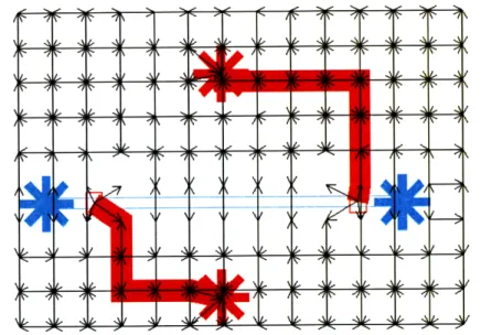
The formulation of the routing problem via a routing graph gains us simplicity and flexibility. As illustrated by Figure 6-1, the map from concrete problem to ab-stract problem is straightforward and flexible. Design constraints and aesthetics are taken into account principally by removing edges in the routing graph. For example, edges that are close and parallel to flow lines are removed, as it would be undesirable for a control channel to closely follow a flow line. In addition, iterative development, a highlight of our implementation described in Section 7, is supported by consider-ing existconsider-ing connections as obstacles, which, like other constraints, simply map to
removed edges in the routing graph.
Figure 6-1: A simple routing problem and solution. The superposition of the concrete problem, in terms of control and flow layers, and the abstract problem, in terms of a routing graph, illustrates the straightforward map from one to the other.
6.2
Algorithm
Let's first overview and explain our algorithm. Our algorithm has two phases. In the first phase, a min-cost max-flow algorithm following [38] finds a solution with minimum wiring length. In the second phase, we iterate over the solution by removing and replacing each connection in turn using a variant of Lee's algorithm [17] to reduce the number of corners. We need the second phase because the routing is constrained to a single layer in microfluidics. In the problem defined in [38] for electronic CAD, the horizontal and vertical edges are on separate layers which allows the min-cost max-flow solution to take into account the cost of vias (i.e. corners), and hence minimize the number of corners as part of the max-flow problem.
Given a routing grid graph G = (V, E) with capacity U, source blocks S1,...,S and sink blocks TI,...,T,, the network graph GN = (VN, EN) is constructed as follows:
node, sl,..., s, are subsource nodes (one per source block), and tl,..., tn are subsink nodes (one per sink block).
edges EN = E U {(s, si)l1 < i < n} U {(tj,t)l1 < j m} U {(s,v)1 < i <
n,v_ E Si} U {(v--,tj)l1 < j < m,v_
C
T}. (N.B. the last two edge setsby-pass the capacity of the grid nodes.)
edge capacity For edges e E E, UN(e) = U(e); for edges e C EN - E, UN(e) = 1.
node capacity For v E V, UN(v) = U(v); other nodes have unlimited capacity.
cost function For edges e
c
E, CN(e) = 1; for edges eC
EN - E, CN(e) = 0.We find the min-cost max-flow of the constructed network graph using the well-known double scaling algorithm [1, 12]. It is straightforward to map back to a solution: see [38] for more details.
We iterate over the min-cost max-flow solution by repeatedly removing each con-nection and replacing it with one that minimizes number of corners without affecting the wiring length. Each step improves the solution by reducing the number of corners while keeping the wiring length constant, so the solution converges to a local opti-mum. In our experience, the iterative process stabilizes relatively quickly (usually less than 3 full rounds). Figure 6-2 illustrates the result of this iterative process.
6.3
Analysis
The running time of our algorithm is polynomial. More precisely, the first phase, the min-cost max-flow phase, runs in O(IV I|E log log Uma. log(VCmax)), like in [38]. The second phase, the iterative stabilization phase, runs in O(in VI) where i is the number of iterations until stabilization. i is typically a single-digit number, and because at least one route is improved at each iteration, it is guaranteed to be finite.
Like the eCAD algorithm that we have adapted, our algorithm only guarantees to find feasible and optimal routes for a given grid size. However, it is possible that no solution exists for a given grid, even though one exists for a finer or even coarser grid.
Thus, we further derive theoretical conditions under which we can guarantee both feasibility and optimality: all edges of valves need to be exactly a distance D from grid lines, where D is half the control channel width plus the minimum separation from channel to valve; similarly, for the bounding box of punches but using the minimum separation from channel to punch instead. Indeed, we did not find a way to separate channels by more than the grid size, as all our attempts to do so lead to problems that cannot be reduced to network flow or other polynomial time algorithms.
Our algorithm still relies on manual punch placement, which is a limitation, as it may declare, that a chip is unroutable when in fact it is routable using other punches. As demonstrated in section 8, our algorithm performs well in practice.
Figure 6-2: Routing of a chip after min-cost max-flow step (top) and after one iteration of ripping and redoing each connection (bottom).
Chapter 7
Implementation
Micado is a working implementation of our ideas, structured as a plug-in to AutoCAD. Figures 7-1, 7-2 & 7-3 present screenshots of Micado.
Micado supports iterative development at each stage. The designer can readily switch back and forth between drawing the flow, annotating the flow, generating the control logic & signals, routing and programming. In the control inference for example, the user can supply some of the valves, and ask Micado to infer and generate the rest; or the user can choose to delete or move some of the valves after they have been generated. As another example, the user can add more channels and flows, and re-invoke Micado to complete the routing without affecting previously routed channels. Finally, the flow annotations are maintained by Micado when possible, even as the user re-designs the flow by removing, adding or moving lines or punches. As shown in Table 7.1, Micado has many setting parameters, which is an added benefit of the tool, because designers can change parameters easily, without having to manually redraw anything.
Micado is freely available at http://cag.csail.mit.edu/micado/. The website in-cludes screencasts, documentation, and the entire source code released under the GPLv2.
Figure 7-1: Micado screenshot. The flow has been drawn manually and annotated graphically. The user is about to click the button to generate the control logic.
Figure 7-2: Micado screenshot. The control components were automatically generated by a single user click. The user added each control punch by a single click at their center. The user is about to click the button to connect control channels to control
Figure 7-3: Micado screenshot. The control layer is complete. The user created two rectangles as place-holders for the flow manipulation buttons, which were automat-ically generated at his request. The user is about to click the button to export the drawing to a programmable GUI.
__-i
I 1111- L 21 1_ilkil.~... . . 2IS I-Z _ I i
-- T11 ib J L L LJ Ii 11 iL L[ 7 LI ,;a . 10 0 p p
0
4CF]LU
time = 0.81 s lock down p open all 0 mix delay = 5msFigure 7-4: Screenshot of a programmable GUI generated by Micado.
Table 7.1: Setting parameters for Micado.
Parameter Suggested value
Width of control channel 50pm
Ratio of valve width to flow width 2 Ratio of valve height to flow width 1.5
Punch radius 100pum
Number of bars for punch 8
Width of each bar for punch 20yum
Extra space around flow line 25ipm
Extra space around valve 40rpm
Chapter 8
Evaluation
We have evaluated our work on real chips and our tool has been used successfully by microfluidic designers. In this section, we present how we applied our techniques for design automation to real chips, summarized in Table 8.1.
Table 8.1: Summary of the features of the real chips evaluated and presented. Name Figure # Flow Punches # Control Channels
Cell culture Fig. 8-1 7 16
Waveform generator Fig. 8-2 17 27
Metabolite detector Fig. 8-3 18 16
The chip in Figure 8-1 has been used for a cell culture of a large embryonic cell, with a recirculation loop and sample extraction [32].
The chip in Figure 8-2 has been used for microfluidic temporal cell stimulations. With the programmable GUI, the user can generate complex chemical waveforms and perform multiple assays on individually addressable cell chambers.
The chip in Figure 8-3 has been used for analysis of preimplantation embryos [33]. The 6 inputs on the left are reserved for supply of enzyme cocktails and wash buffers. The 10 inputs on the top are used for loading media samples and calibration standards. Assays are performed by metering samples of culture media into the central mixing ring and combining them with a metabolite specific cocktail. A camera on top of part of the mixer records fluorometric measurements.
succeeding even in highly dense chips. After a setup phase of less 5 seconds or less, all chips were routed in less than 1 second.
Our flow annotations are suitable for describing the flow in these chips and our control inference algorithm is suitable for generating the control components of these chips, with three exceptions: the waveform pumps and cell isolators on the waveform generator chip, and the mixer isolator on the metabolite detector chip. Incorporating these constraints is the subject of future work. We describe more precisely the issues in annotating and inferring these features. On the waveform chip, valves are needed to separate individual cell chambers. Since they reflect absence of a flow, rather than a flow itself, they do not fall into our existing flow annotations. Such "separation" primitives could be added in the future, but currently demand manual valve placement by the user. Though we can infer the waveform pumps, we cannot specify their precise control, as the pumps need to be toggled in a specific ratio: for example, 30% from one channel, 70% from the other, switching faster than a human could do by hand.
The programmable GUIs were easily extended to automatically record camera measurements. Figure 8-4 shows the control GUI for one of the chip. Microfluidic de-signers who have used our tool were particularly pleased by the automatic generation
of the programmable GUI.
Our work represents a first step towards scalable design of multilayer microfluidic chips.
**e
*I
*je
*I
*I
**Cal
L 01]Ii
*
*
*
*
*
**
Figure 8-1: Cell culture chip with 1 chamber before (top) and after (bottom) auto-matic routing by single-clicking.
OOEI OEEOF
*
*
*
* I ,
l i i
O e • •e •e •
*** **e~e+~e~
Figure 8-2: Chemical waveform generator chip with 16 chambers before (top) and after (bottom) automatic routing by single-clicking.
*;
*
*
*
*
+~
*
*(
(
jl
*(
)
Figure 8-3: Metabolite detector chip before (top) and after (bottom) automatic rout-ing by srout-ingle-clickrout-ing.
time - 0.59 s lock down a open al mix delay = 5ms time= 1.29 s lock down e open all mix delay = 5ms
Figure 8-4: Example of generated visual tool for controlling chip, before (top) and after (bottom) single-clicking on an instruction, which opens a flow path from an input to the chamber. The open valves are in blue, the closed valves in red.
-
-..r-,Ll
---Chapter 9
Related Prior Work
9.1
CAD for Microfluidics
Prior work in microfluidic CAD targets a different technology, based on the manip-ulation of fluids as droplets [22, 7]. [6] provides a good overview of prior work and trends in design automation for droplet-based microfluidics. See also [4, 28, 39, 27, 41, 40, 8, 26]. While droplet-based chips [23] are attractive in their flexibility, there are challenges in maintaining precision while dispensing droplet volumes and splitting droplets into pieces.
9.2
CAD for Electronics
Some previous work in electronic CAD is relevant to laying out the control layer of microfluidic chips. The book by Lengauer [18] provides a good survey of the general techniques of integrated circuit layout. There are many opportunities to effectively adapt CAD algorithms from electronics to microfluidics, as we did with a routing algorithm [38] in Section 6.
9.2.1
Differences between electronic CAD and microfluidic
CAD
In microfluidics, layouts are very constrained due to the high cost of additional control layers. In particular, a chip usually has just one layer for the layout of the control. For this reason, techniques devised for two-layer wiring, such as [38], need to be adapted before applying to microfluidics. Also, due to the cost and complexity of off-chip interconnects, there is a lot of effort to minimize the number of control channels
needed.
In addition, the design and aesthetic constraints are different.
* Some features are diagonal (e.g., valves on a circular mixer) and would require a high grid resolution or non-rectilinear grid to precisely capture the constraints.
* Though intersections between control channels and flow channels are necessary to layout many chips, they should be minimized.
* Valves can be connected to each other, sharing the connection to a punch.
* Flow punches are typically placed in a different area of the chip than control punches.
* Channels connecting valves to punches can be diagonal.
Because the complexity of microfluidic chips is still (barely) manageable by hand, additional aesthetic constraints are necessary for adoption, in order to appease de-signers' desire for aesthetically pleasing chips.
Because microfluidic chips are easy to fabricate (graduate students go through several fabrication cycles in a week), the design is frequently modified and refined. This contrasts with electronic chips that are fabricated very infrequently (place-and-route can run once in a year). Thus we need interfaces and abstractions that support iteration, as well as algorithms that are fast enough for real-time usage.
9.3
Abstractions for Microfluidics
Previously, our group [29] and others [2, 3] have researched high-level programming abstractions to enable users to easily write complex experiments for a given chip design. While these efforts also included a notion of a microfluidic ISA, the ISA was designed for an existing chip, rather than serving as a specification for the control logic of a new chip. To the best of our knowledge, this thesis is the first to automate steps of the design process for multilayer soft-lithography chips.
Chapter 10
Conclusion
This thesis formulates two new problems for microfluidics CAD, and proposes the first known solution to each. The first problem is the inference of control logic for a given instruction set. We prove that minimizing the number of control channels needed is NP-hard and offer a heuristic algorithm that works well in practice. We also provide the first interface for hierarchically specifying the instruction set of interest. The second problem is the routing of control channels to user-defined punches. We adapt an algorithm from electronic CAD, deriving an appropriate grid size and extending it to satisfy aesthetic constraints, in order to arrive at a good solution.
We implemented our algorithms in an AutoCAD plug-in, called Micado, which we have released to the research community. To our knowledge, this tool is the first to automate the design of multilayer microfluidic chips. While such design tools have been in development for droplet-based microfluidic processors, our work is the first to target the broad class of soft-lithography chips. Such automation will be critical if we are to fully exploit the potential of building scalable and programmable microfluidic chips with millions of independent parts.
Bibliography
[1] Ravindra K. Ahuja, Andrew V. Goldberg, James B. Orlin, and Robert E. Tarjan. Finding minimum-cost flows by double scaling. Math. Program., 53(3):243-266, 1992.
[2] Ahmed M. Amin, Mithuna Thottethodi, T. N. Vijaykumar, Steven Wereley, and Stephen C. Jacobson. Aquacore: a programmable architecture for microfluidics.
SIGARCH Comput. Archit. News, 35(2):254-265, 2007.
[3] Ahmed M. Amin, Mithuna Thottethodi, T. N. Vijaykumar, Steven Wereley, and Stephen C. Jacobson. Automatic volume management for programmable microfluidics. SIGPLAN Not., 43(6):56-67, 2008.
[4] K. Bohringer. Modeling and controlling parallel tasks in droplet-based microflu-idic systems. IEEE Transactions on Computer-Aided Design of Integrated
Cir-cuits and Systems, special issue on Design Automation Methods and Tools for Microfluidics-Based Biochips, 25(2):329-339, 2 2006.
[5] David N. Breslauer, Philip J. Lee, and Luke P. Lee. Microfluidics-based systems biology. Molecular BioSystems, 2, 2006.
[6] K. Chakrabarty and J. Zeng. Design automation for microfluidics-based biochips.
ACM Journal on Emerging Technologies in Computing Systems, 1(3):186-223,
10 2005.
[7] Sung Kwon Cho, Hyejin Moon, and Chang-Jin Kim. Creating, transporting, cutting, and merging liquid droplets by electrowetting-based actuation for digital microfluidic circuits. Microelectromechanical Systems, Journal of, 12(1):70-80, Feb 2003.
[8] Daniel Davids, Siddhartha Datta, Arindam Mukherjee, Bharat Joshi, and Arun Ravindran. Multiple fault diagnosis in digital microfluidic biochips. J. Emerg.
Technol. Comput. Syst., 2(4):262-276, 2006.
[9] D.C. Duffy, J.C. McDonald, O.J.A. Schueller, and G.M. Whitesides. Rapid pro-totyping of microfluidic systems in poly(dimethylsiloxane). Analytical Chemistry, 70(23):4974-4984, 1998.
[10] David Erickson and Dongqing Li. Integrated microfluidic devices. Analytica
[11] Joseph Farfel and Darko Stefanovic. Towards practical biomolecular computers using microfluidic deoxyribozyme logic gate networks. In DNA 11, 2005.
[12] Antonio Frangioni and Antonio Manca. A computational study of cost reopti-mization for min-cost flow problems. INFORMS J. on Computing, 18(1):61-70, 2006.
[13] A. Gehani and J. Reif. Micro flow bio-molecular computation. Biosystems, 52, 1999.
[14] William H. Grover and Richard A. Mathies. An integrated microfluidic processor for single nucleotide polymorphism-based DNA computing. Lab on a Chip, 5, 2005.
[15] J.W. Hong and S.R. Quake. Integrated nanoliter systems. Nature Bio Technology, 21(10):1179-1183, 2003.
[16] R. Karp. Reducibility among combinatorial problems. In R. Miller and J. Thatcher, editors, Complexity of Computer Computations, pages 85-103. Plenum Press, 1972.
[17] C.Y. Lee. An algorithm for path connections and its applications. IRE
Trans-actions on Electronic Computers, EC-10(2):364-265, 1961.
[18] Thomas Lengauer. Combinatorial Algorithms for Integrated Circuit Layout. John Wiley and Sons, New York, 1990.
[19] Michael S. Livstone, Ron Weiss, and Laura F. Landweber. Automated design and programming of a microfluidic DNA computer. Natural Computing, 2006. [20] John S. McCaskill. Optically programming DNA computing in microflow
reac-tors. BioSystems, 59, 2001.
[21] Jessica Melin and Sephen Quake. Microfluidic large-scale integration: The evo-lution of design rules for biological automation. Annual Reviews in Biophysics
and Biomolecular Structure, 36:213-31, 2007.
[22] Michael G. Pollack, Richard B. Fair, and Alexander D. Shenderov. Electrowetting-based actuation of liquid droplets for microfluidic applications.
Applied Physics Letters, 77(11):1725-1726, 2000.
[23] Hong Ren, V. Srinivasan, and R.B. Fair. Design and testing of an interpolating mixing architecture for electrowetting-based droplet-on-chip chemical dilution.
TRANSDUCERS, Solid-State Sensors, Actuators and Microsystems, 12th Inter-national Conference on, 2003, 1:619-622 vol.1, June 2003.
[24] Samuel K. Sia and George M. Whitesides. Microfluidic devices fabricated in poly(dimethylsiloxane) for biological studies. Electrophoresis, 24, 2003.
[25] Koutaro Somei, Shohei Kaneda, Teruo Fujii, and Satoshi Murata. A microfluidic device for DNA tile self-assembly. In DNA 11, 2005.
[26] Fei Su and Krishnendu Chakrabarty. Yield enhancement of reconfigurable microfluidics-based biochips using interstitial redundancy. J. Emerg. Technol.
Comput. Syst., 2(2):104-128, 2006.
[27] Fei Su and Krishnendu Chakrabarty. High-level synthesis of digital microfluidic biochips. J. Emerg. Technol. Comput. Syst., 3(4):1-32, 2008.
[28] Fei Su and Jun Zeng. Computer-aided design and test for digital microfluidics.
IEEE Design and Test of Computers, 24(1):60-70, 2007.
[29] William Thies, John Paul Urbanski, Todd Thorsen, and Saman Amarainsghe. Abstraction layers for scalable microfluidic biocomputing. Natural Computing, May 2007.
[30] Marc A. Unger, Hou-Pu Chou, Todd Thorsen, Axel Scherer, and Stephen R. Quake. Monolithic microfabricated valves and pumps by multilayer soft lithog-raphy. Science, 288(5463):113-116, April 2000.
[31] John Paul Urbanksi, William Thies, Christopher Rhodes, Saman Amarasinghe, and Todd Thorsen. Digital microfluidics using soft litography. Lab on a Chip, 6(1):96-104, 2006.
[32] John Paul Urbanski. Microfluidic Tools for Metabolomics. PhD thesis, Mas-sachusetts Institute of Technology, September 2008.
[33] John Paul Urbanski, Mark T. Johnson, David D. Craig, David L. Potter, David K. Gardner, and Todd Thorsen. Noninvasive metabolic profiling using microfluidics for analysis of single preimplantation embryos. Analytical
Chem-istry, 80(17):6500-6507, 2008.
[34] Danny van Noort. A programmable molecular computer in microreactors. In
DNA 11, 2005.
[35] Danny van Noort, Frank-Ulrich Gast, and John S. McCaskill. DNA computing in microreactors. In DNA 8, 2002.
[36] Danny van Noort and Byoung-Tak Zhang. PDMS valves in DNA computers. In SPIE International Symposium on Smart Materials, Nano-, and Micro-Smart
Systems, 2004.
[37] E. Verpoorte and N.F. De Rooij. Microfluidics meets mems. Proceedings of the
IEEE, 91(6):930-953, June 2003.
[38] Hua Xiang, Xiaoping Tang, and D. F. Wong. Min-cost flow-based algorithm for simultaneous pin assignment and routing. IEEE Transactions on
[39] Tao Xu and Krishnendu Chakrabarty. Integrated droplet routing and defect tolerance in the synthesis of digital microfluidic biochips. J. Emerg. Technol.
Comput. Syst., 4(3):1-24, 2008.
[40] Tao Xu, William L. Hwang, Fei Su, and Krishnendu Chakrabarty. Automated design of pin-constrained digital microfluidic biochips under droplet-interference constraints. J. Emerg. Technol. Comput. Syst., 3(3):14, 2007.
[41] Ping-Hung Yuh, Chia-Lin Yang, and Yao-Wen Chang. Placement of defect-tolerant digital microfluidic biochips using the t-tree formulation. J. Emerg.