HAL Id: hal-01502419
https://hal.archives-ouvertes.fr/hal-01502419
Submitted on 5 Apr 2017
HAL is a multi-disciplinary open access archive for the deposit and dissemination of sci-entific research documents, whether they are pub-lished or not. The documents may come from teaching and research institutions in France or abroad, or from public or private research centers.
L’archive ouverte pluridisciplinaire HAL, est destinée au dépôt et à la diffusion de documents scientifiques de niveau recherche, publiés ou non, émanant des établissements d’enseignement et de recherche français ou étrangers, des laboratoires publics ou privés.
Prediction and control of combustion instabilities in real
engines
Thierry Poinsot
To cite this version:
Thierry Poinsot. Prediction and control of combustion instabilities in real engines. Proceedings of the Combustion Institute, Elsevier, 2017, vol. 36 (n° 1), pp. 1-28. �10.1016/j.proci.2016.05.007�. �hal-01502419�
To link to this article : DOI: 10.1016/j.proci.2016.05.007 URL :
http://dx.doi.org/10.1016/j.proci.2016.05.007
This is an author-deposited version published in:
http://oatao.univ-toulouse.fr/
Eprints ID: 17713
O
pen
A
rchive
T
oulouse
A
rchive
O
uverte (
OATAO
)
OATAO is an open access repository that collects the work of Toulouse
researchers and makes it freely available over the web where possible.
To cite this version: Poinsot, Thierry Prediction and control of
combustion instabilities in real engines. (2017) Proceedings of the
Combustion Institute, vol. 36 (n° 1). pp. 1-28. ISSN 1540-7489
Any correspondence concerning this service should be sent to the repository administrator:
Prediction
and
control
of
combustion
instabilities
in
real
engines
T.
Poinsot
a,b,c,∗aIMFToulouse,INPdeToulouseandCNRS,Toulouse31400,France bCERFACS,Toulouse31057,France
cCenterforTurbulenceResearch,Stanford,CA94305,USA
Abstract
Thispaperpresentsrecentprogressinthefieldofthermoacousticcombustioninstabilitiesinpropulsion en-ginessuch asrockets orgasturbines.Combustioninstabilitieshave beenstudied formore than acentury insimplelaminarconfigurationsaswellasinlaboratory-scaleturbulentflames.Theseinstabilitiesarealso encounteredinrealenginesbutnewmechanismsappearinthesesystemsbecauseofobviousdifferenceswith academic burners: largerReynoldsnumbers, higher pressuresand powerdensities, multiple inletsystems, complexfuels.Otherdifferencesaremoresubtle:realenginesoftenfeaturespecificunstablemodessuchas azimuthal instabilities ingas turbinesor transverse modes in rocket chambers. Hydrodynamic instability modescanalsodifferaswellasthecombustionregimes,whichcanrequireverydifferentsimulationmodels. Theintegrationofchambersinrealenginesimpliesthatcompressorandturbineimpedancescontrol instabil-itiesdirectlysothatthedeterminationof theimpedancesof turbomachineryelementsbecomesakeyissue. GatheringexperimentaldataoncombustioninstabilitiesisdifficultinrealenginesandlargeEddysimulation (LES)hasbecomeamajortoolinthisfield.Recentexamples,however,showthatLESisnotsufficientand thattheory, eveninthesecomplex systems,plays amajorrole tounderstandbothexperimental andLES resultsandtoidentifymitigationtechniques.
Keywords: Instabilities;LES;Thermoacoustics;Gasturbines
1. Introduction
Mostcombustionsystemsaredesignedto oper-ateinstableregimes.However,allexperimentalists
∗ Correspondenceto:IMFToulouse,INPdeToulouse andCNRS,31400Toulouse,France
E-mailaddress:[email protected]
workingonsteadycombustionchambers(furnaces, gasturbines,powerplants)knowthat’sometimes’, achamberstartsexhibitingunexpectedoscillations. These combustion instabilities (often called ther-moacoustic)leadtoadditionalnoiseandvibration, which can be ignored or tolerated if the level of oscillationsremainssmall(lessthanafewmbars). Inothercases, however, pressurefluctuationscan reach values of the order of a large fraction of
the mean pressure and leadto more serious con-sequences:thechambercanquench,theflamecan flashback and burn part of the injection system. The pressure oscillations can also become large enoughtodamagethecombustorstructureorlead totheexplosionoftheengine.
Combustioninstabilities(CIs),alsocalledflame dynamics, are an important field of combustion research. It combines all usual sciences involved in reacting flows (kinetics, transport, fluid me-chanics, thermodynamics) but also requires the introduction of acoustics, hydrodynamic stabil-ity, dynamical systems and control theory. Even thoughCIscan appearinalmostanycombustion system,industryisnotespeciallykeenonstudying themorinrecognizingthattheycanbeaproblem in their company’s engines. The main reason for this is thatCIs are the cause of major problems, which are difficult to master because they occur duringthelast stagesof developmentandarestill difficulttopredicttoday:havinganunstableengine isstillsimilartocatchingsomekindof diseasefor companies. Since theadventure of theF1 engine during theApolloprogram inthe60s,which cost billions of dollars beforeasolutionwasfound to mitigate CIs [1], companies know that CIs are a major industrial risk, for which communication may not be the best solution. CIs have been the hidden and feared problem of many combustion programs,startingwithsolidandliquidfuelrocket enginesinthe50sandcontinuingmorerecentlyin gasturbines,industrial furnacesorevendomestic heaters.
Laboratories,ontheotherhand,haveno diffi-cultystudyinginstabilitiesincanonicalcasessuch aslaminarpremixedflamesandtheliterature con-tains avery largeamount of research work dedi-catedtoCIsinsimpleflames[2–9].Whenitcomes torealengines,1 thesituationisdifferent.Here,CI
mechanisms involve notonly thosefound in aca-demicexperiments,butalsointroducenewphysics thatisusuallynotstudiedinlaboratories:
• Realflamesareturbulentandmanyofthem are swirled and confined in complex shape chambers. CIs in turbulent swirled flames are now commonly studied in laboratories
[10–18] but usually in simplified chambers thatdonotcontainthecomplexitiesfoundin realengines.
• Power density is known to be an impor-tant parameter for instabilities: when com-bustion chambers become smaller or when theirpowerincreases,CIsaremoreproneto appear.Thisusuallyoccursforhigh-pressure systems,which aremoredifficulttostudyin laboratories.The bestexample is transverse
1 Theterm’realengine’willbeusedheretodesignate en-ginesusedinrealindustrialsystems,asopposedto cham-bersstudiedinlaboratoryenvironments.
modes in rocket engines [19,20], which ap-pearonrealsystemsbutaredifficultto trig-ger in laboratory set-ups, which are scaled downintermsofpressureandpowerdensity
[21–23].
• Most laboratories study instabilities in gaseous flames. Even if research on CIs actually started in the 50s for liquid-fueled systems [24–26], studying instabilities in liquid fueled combustors is much more complicated[27,28].
• Thegeometryofthechamberisafirst-order parameterfor CIs:ingasturbines, combus-tion chambers have annular shapes where azimuthal instability modes can develop, somethingthathadneverbeenstudiedin lab-oratories untilvery recent times [29–31] for obviouscost reasons. Therefore the physics of azimuthal modes was known mainly on the basis of limited experimental observa-tionsperformedonrealfullturbines[32–34]. • Laboratoryburnersusesingleinjection sys-tems,which create isolated flames.Gas tur-bineschamberscanhavetwentyinjectorsand flames.Rocketchambersfeaturehundredsof injectors: therefore flame/flame interactions aredominant in real engines and absentin mostlaboratoryburners.
• Most instability modes studied in labora-tories involve longitudinal acoustic modes, which propagate along the flow direction. In real engines, modes can also be trans-verse,radialorazimuthal.Moreimportantly, modescanbemuchmorenumerousthanin alaboratoryexperimentbecausereal config-urations are geometrically complex. An in-dustrial gasturbine can exhibit30 acoustic eigenmodes between 0 and 250 Hz, many of themhavingthecapacitytobecome self-excited [34]. This never happens in labora-torysystems,whicharemuchsimpler.Being abletorecognizewhichmodeappearsinsuch asystembecomessignificantlymore compli-catedthaninalaboratoryscaleexperiment, whereonlyafewmodescanbefoundandare easilyidentifiedbytheirfrequencies.
• Many unstable modes studied in laborato-ries correspondto situationswhere entropy wavesplayalimitedrole.Inchambers termi-natedbyanozzle orbyastator/rotorstage, entropywavescanbereflectedbackas acous-tic waves into the chamber, creating a new classof CI,calledentropy-acousticmodes. Fluctuationsofequivalenceratioarealso en-countered inmany realengines, where they caninducespecificCImodes.
• Finally, simple, well-defined inlet and out-let conditions (imposed pressure or im-posed velocity) can be imposed to control acousticreflectionsinlaboratorycombustors (Section4.3).Thisisdifferentinrealengines.
Fig.1. Rocketengine destroyedbyinstabilityduringtheearlyyearsof theUSrocketprogram(left)andalaboratory burnerexhibitingbothstableandunstableregimes(right)[38].
Ingasturbines,forexample,thechamberis fed by a compressor and blows into a tur-bine. Determining the impedances of these elementsisadauntingtaskinitself.
This review discusses combustion instabilities appearing in engines. Its objective is to describe modern simulation methods combined with new experimentsandtheoreticaldevelopmentsforsuch instabilities.Readersarereferred to otherreviews for complete descriptions of instability mecha-nisms[20,35–37].Ofcourse,thepresentationbuilds onfundamentalresultsobtainedforCIsin labora-toriesoverthelasthundredyearsbutitsmaingoal istodiscusswhatmustbeaddedtotheseelements whenrealenginesareconsidered.
ThermoacousticCIsareduetocoupling mech-anismsbetweenunsteadycombustionandacoustic waves propagating in the chamber and reflecting on its walls, inlets and outlets.2 The left image
of Fig. 1 shows a NASA rocket engine partially destroyed after the engine encountered CI while the rightpicturedisplays high-speed viewsof the flow in alaboratory premixedburner for astable andanunstableregime[38]:theinstabilitychanges the flow drastically, creating mushroom-shaped vorticesatafrequencyof 530Hzandaveryshort and intense turbulent flame that can destroy the chamberinafewminutes.3
Fromafundamentalpointof view,CIs consti-tuteoneofthemostchallengingproblemsinfluid mechanics: they combine turbulence, acoustics,
2 Mostunconfinedflamesdo notexhibitstrong com-bustioninstabilities.
3 Inarealcombustor,thiscanbemuchfaster:a fighter-aircraftenginesubmitted toscreech,astrong CImode, orarocketenginewhereatransversemodegrowscan ex-plodeinafewseconds.
chemistryandunsteadytwo-phaseflowincomplex geometries. The scales to capture vary from the laminarflamethickness (lessthan0.1 mm)tothe acousticwavelengths(afewmeters)andthespeeds from flame speeds (less than 1 m/s)to the sound speed(morethan600m/sintheburntgases). Com-putingCIsismoredifficultthancomputingsteady combustionandrequiresmore sophisticatedtools because they must capture unsteady phenomena and unstable mechanisms. The intensity of the acousticfieldgeneratedby aflame intheabsence of CI is small: the acoustic power created by a combustor is typically less than 10−8 times the
combustorpower.Predictingpreciselytheacoustic fieldcreatedbyaflameismuchmoredifficultthan simulating theflame itself [39,40]. Evenif such a small conversion factor from mechanical energy tosoundleadstoarelativelysmalllevelof energy contained in the acoustic field, these acoustic fluctuationscanhaveastrongeffectontheflames themselves,closingaresonantfeedbackloopwhich is difficult to predict: capturing flame / acoustic coupling to predict self-sustained instabilities is oneoftheoverarchingsimulationproblemsinthe combustioncommunity.
The basic mechanisms leading to combustion instabilitieswereidentified150yearsagobyLord Rayleigh[41] but theyhave become real research topics as well as practical dangers for many in-dustrialprogramswhenthepowerdensityof com-bustionchambershasincreasedsufficiently,firstin rocket[24]andlaterinjetengines[19,42,43]. Stud-iesofcombustioninstabilitiesandnoiseare numer-ous[24,26,44–53]andstartedlongago[41].Aflame isnotneededtoproducesuchcoupling:asshown byRijke[54,55],aheatedgauzeplacedinatubeis enoughtoproducea“singing” tubecausedbythe couplingbetween the acousticmodes of theduct andtheunsteadyheatreleasedbythegauze[56,57].
However, whenthe heatreleaseis due toaflame, more energy can betransmittedinto theacoustic fieldandtheeffectsof combustioninstabilitiesare muchmoredangerous.
CIsarealsoknownunderothernamessuchas thermoacoustics inflames orcombustion dynam-ics:theHottellectureofS.Candelin2002[35] pro-videsaprecisehistoryof CIresearchandof meth-ods used tocontrolthem. Thebooksof Lieuwen andYang[36]andCulick[19]describeCIphysics inmultiplerealcombustionsystems.Theobjective of thepresentlectureis nottorepeatthese excel-lentreviewsbuttocomplementthembydiscussing importantprogressachievedinthelast10yearsin thefieldof CImodelingand simulation.Amajor revolution in this domain has been the introduc-tionofLESmethodsforCIcomputations.LEShas become one essential tool to analyze CIs but, as showninthenextsections,itisnotsufficienttofully analyzeCI:likeexperiments,LEScantellwhether agivencombustorwillbeunstablebutitdoesnot tellwhythisissoandhowwecancontrolthis insta-bility. Tounderstandwhyinstabilitiesappear and howtocontrolthem,otherapproachesareneeded suchastheoryandsimplifiedsimulationtools (lin-earizedEulerequations,forexample),whichwillbe discussedinthenextsections.
Thepresentpaperfocusesongasturbines:they provide excellent examples of CIs that require morestudiesthanlaboratorysystemsbecausethey lead to completely new physics. First, a simple pedagogical model of dump combustor is de-scribed to recall classical coupling mechanisms betweenflamesandacousticsandintroduce stabil-ity criteria(Section 2.1). Simulation methods for CIs arepresented in Section 2.2, beforeapplying them to the specific case of gas turbine engines in Section 3, which discusses recent LES and experimental results on annular chambers. The configurations that will be presented, are typical of gas turbine engines (Section 3.1) and they exhibitazimuthal modes thatcannotbeobserved in usual laboratory set-ups. Recently, theory has beenintroducedwithsignificantsuccesstoanalyze these modes (Section 3.2). CI control methods in annularchambers havealso becomea topicin itself, that is discussed in Section 3.3. After this section,thepresentationopenstonewtopicsthat
are relevant for annular chambers but to other engines aswell (Section 4): thecoupling between wallheattransferandCIs(Section4.1),therecent discoveryofintrinsicacousticmodes(Section4.2), the need to consider impedances to analyze CIs (Section 4.3, which is critical for gas turbines), recentresultsonhydrodynamicstabilityofswirled flows (Section 4.4) and the existence of flame bifurcations in swirled combustors that can be triggeredbyCIs(Section4.5).Finally,theneedto introduceUQ(UncertaintyQuantification)forCI studiesisthetopicof Section4.6.
2. Modelingandcomputingcombustion instabilities
2.1. A model problem illustrating key features of combustion instabilities
Most CIs aredue to a resonance between un-steady combustion processes and acoustic waves propagating in the combustion chamber. The mechanisms leading to anamplification of com-bustion/acousticprocessesarebestexplainedby be-ginningwith thesimple modelproblem described in Fig. 2. Consider a constant cross-section duct whereaflameisstabilizedatthedumpplane sepa-ratingtheinjectiontube(lengthl 1,sectionS 1)and
thecombustionchamber(lengthl 2,sectionS 2).
For low-frequencylongitudinal modes, planar acousticwavespropagatebothintheinjectiontube and the chamber so that the fluctuating acoustic pressure(p ′
i)and velocity(u ′i)signals inthesetwo ducts(numbered i =1to2, x =0corresponds to theflameposition)are:
u ′ i(x,t) = 1 ρic i Re ¡£A + i e jkix−A − i e −jkix¤e −jωt¢ (1) p ′ i(x,t) = Re ¡£ A + i e jkix+A − i e −jkix¤e −jωt¢. (2)
wherek i=ω/c iisthewavenumberinducti, ωthe pulsationand c ithesoundspeedinduct i .To de-terminetheacousticwaveamplitudes A −
1, A + 1,A − 2 and A +
2, boundaryconditions areimposed at the
inlet (usually u ′
1 =0 because velocity is imposed)
andattheoutlet(usually p ′=0forchambersopen
Fig.2. Asimplepedagogicalmodelforcombustioninstabilities:alaminarflamestabilizedatthedumpplaneseparating theinjectionductandthecombustionchamber.Thecolorfieldisthevelocitymodulus[58].
totheatmospherewhere pressureisconstant).At thedumpplanewheretheflameisstabilized,jump conditionsfromonesideof theflametotheother allowtorelatepressureandvelocityperturbations onbothsidesoftheflamefront,assumingthatthe flame is compact compared tothe acoustic wave-length. Through such a compact flame, pressure perturbationsareconservedwhiletheunsteady vol-ume flow rate increases because of the total un-steadyheatreleaseintheflameÄ˙′[49,59,60]:
p ′ 2(x=0,t) = p ′ 1(x=0,t) and S 2u ′2(x=0,t) = S 1u ′1(x=0,t) + γ −1 ρ1c 21 ˙ Ä′ (3)
whereρjisthemeandensityinsection j andγ the ratioof specificheats.AconvenientscalingforÄ˙′
is to express it as a function of the chamber in-letvelocityfluctuationsu ′
1,asproposedbyCrocco [24]whointroducedaninteractionindeed n (mea-suring the strength of the flame response) and a time delay τ (measuring thetime requiredby the flametoreacttoforcing):
γ −1 ρ1c 21S 1
˙
Ä′= nu ′
1(x=0,t −τ) (4)
sothat,assumingharmonic variationsforall per-turbations f ′
= f ˆe −jωt,jumpconditionsbecome: ˆ
p 2(x=0,t) = p ˆ1(x=0,t) and
S 2u ˆ2(x=0,t) = S 1u ˆ1(x=0,t)(1 +ne jωτ) (5) Eq. (4) is the heart of most CI models: it allows linkingheatreleasefluctuations(duetoconvective and chemicaleffects) toa singleacousticvelocity at thechamber inlet (x =0).Once it is accepted, thereisnoneedtosolveforanyothermechanisms exceptthanacoustics.ThewholeproblemofCI be-comes an acoustic problem only, and Eq. (3) to-getherwithboundaryconditionsattheinlet (con-stantvelocityatx =−l 1,whichimposesA +1e jkil1−
A − 1e
−jkil1 =0)andattheoutlet(constantpressure
at x =l 2, which imposes A +2e jkil2+A − 2e
−jkil2 =0)
leadstoanhomogeneousequationforthewave am-plitudesA − 1,A + 1,A − 2 andA +
2,whichhasanon-zero
solutiononlyif:
cos µ ωl 2 c 2 ¶ cos µ ωl 1 c 1 ¶ −Ŵsin µ ωl 2 c 2 ¶ sin µ ωl 1 c 1 ¶ ×(1+ne jωτ)=0 with Ŵ = ρ2c 2 ρ1c 1 S 1 S 2 (6)
Eq.(6)isadispersionrelationforω:therealpartof ωisthepulsationofthemodethatwilloccurinaCI oscillation;itsimaginarypartprovidesthegrowth rate. If it is positive, this model predicts thatthe mode willbelinearlyamplified,leading toCI.Of course,thislinearapproachcannotpredictthe am-plitudeofthelimitcyclethatmightbereachedafter
themodestartsgrowing,buttheprevious demon-stration shows that the essence of CI can be de-scribedinonlyafewlines.
The general solution of Eq. (6) is difficult to express but an analytical expression is easily ob-tainedinasimplifiedcasewherethetubeshavethe samesectionsandlengths(S 2=S 1andl 2 =l 1= a )
and theflame inducesa negligibleheat releaseso that ρ2 =ρ1 and c 2 = c 1 = c . In this case, Ŵ =1
andthedispersionrelation becomescos2(ωa/c)−
sin 2(ωa/c)(1+ne jωτ)=0.Intheabsenceof flame (n =0)thesolutionofthedispersionequation sim-ply corresponds to the acoustic eigenmodes of a ductof length2a :thefirstmodeissuchthat k ol = π /4. It has a zero growth rate (ℑ(ko)=0) and a wavelengthλ0=2π /k o=8a (fourtimesthetotal length of the duct 2a ) explaining why this mode iscalledthequarter-wavemode.ItsperiodisT o= 2π /ωo=8a/c .
If theflameisactiveandn isnonzerobutstill small,thesolutionfork canbewrittenasaTaylor expansionaroundk osothatk = k o+k ′with:
Re (k)= π /(4a )− n
4a cos(2π τ /T o) and
ℑ(k)= ℑ(k′)
=− n
4a sin (2π τ /T o) (7)
Since n issmall inthisapproach,thepulsationof themode (Re (k )/c ) is only weaklyaffected by the flameeffect:theunstablemodefrequencyremains close to the quarter-wave frequency without ac-tiveflame.Theactiveflame(n 6=0),however, con-trolsthegrowthrate of themode: thecombustor will be unstable if ℑ(k ) > 0, which implies here sin(2π τ/T o) < 0 or (p+1/2)T o<τ <(p+1)T o where p is aninteger.This instabilitycriterion in-dicatesthatcertainvaluesof theflamedelayτ will leadtheflametoinstability.Forthefirstmode(p = 0),thedelayτ mustbelargerthanthehalf-period
T oof thefirstacousticmodeandlessthanT o:
T o>τ > 1
2T o (8)
Evenif theassumptionsusedtoderivethis sta-bilitycriterionarecrude,thisanalysiscontainsall theingredientsofmanylow-ordermodelsusedfor thermoacoustics:
• It requires all convective and chemistry ef-fectstobemodeledasafunctionofapurely acousticquantity(whichmustbeeither pres-sure oracoustic velocity). Here the Crocco model was used where the unsteady reac-tion rate Ä˙′ is expressed as a function of
the acoustic velocity at the chamber inlet
u ′
1(x=0,t) .Moresophisticatedmodelsmay
befoundintheliterature[6,61,62].Mostof them assume that Ä˙′ depends on previous
values of the reference velocity u ′
1(x=0).
Thisdependenceisusuallyexpressedthrough aflametransferfunction(FTF)F ,depending
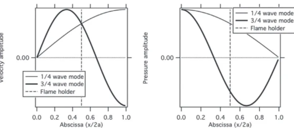
Fig.3. Thestructureofthe1/4and3/4wavemodesinthemodelofFig.2. onthepulsationω: ˙ Ä′/Ä =¯˙ F (u ′ 1(x =0,t∗; t∗ < t) /u ¯(x = 0)) (9) The FTF can also depend on the ampli-tude of the oscillation A inwhich case it is calledanFDF(FlameDescribingFunction)
[63–65].Inmanycombustors,thefreshgases velocitymaynotbetheonlyquantity affect-ing unsteady combustion. The fluctuations of equivalence ratio φ at the chamber in-lethavebeenidentifiedasanotherimportant controlparameter[66–68]sothatpresent ex-pressionsforFDFareoftenwrittenas:
˙
Ä′/Ä =¯˙ F (u ′1(x =0,t) /u ¯(x=0),φ′/φ,¯ A ) (10) • The previous derivation was performed for thefirst acousticmode (1/4wave) butother higher-ordermodescanbeamplifiedtoo.In themodelof Fig.2,thosearethe3/4,5/4... modes.Inmostchambers,onlythelowest or-deracousticmodesareexpectedbecausethe acoustic dissipation increases rapidly with modeorderandfrequency.
• Itleadstoa stabilitycriterionthatdepends onτ (andweaklyon n )inmostcases.When
k isdetermined,themodestructures(i.e.the dependence on p ′ and u ′ on spatial
coordi-nates)can beobtained too.As anexample,
Fig.3displaysthestructureof thefirsttwo modes(1/4and3/4wave).
2.2. Classification of simulation methods for combustion instabilities
Twomainclassesoftechniquesareusedto sim-ulatecombustioninstabilities(Fig.4):thefirst cat-egory;andtheonlyoneuntilthe2000s,is thermoa-cousticcodes(calledTAhere)inwhichflamesare notsimulatedbutreplacedbytheirequivalentFTF orFDF[69–72]. Themeanflow isfrozen and so-lutionsaresoughtforthelinearizedperturbations. Thetoymodelof Fig.2isanexampleof such an
approachinaone-dimensionalcase.More sophis-ticatedmethodscan bedevelopedinthree dimen-sions,intimeorFourierspacebuttheyallsharethe samebasic idea: avoiding thecomplexity of flow andchemistrybylumpingalltheireffectsintosome formofFDF.
FTFsandFDFsrequiredforTAmodescanbe obtainedanalytically in simplecases [9,40,73], or experimentally [64,74]. To complement these ap-proaches, a second class of methods was intro-ducedaround2000tocomputeexplicitlytheflame dynamics,usingfullLESoftheforcedreactingflow
[14,75,76].Thisismoreexpensiveanditraises vari-ousdifficultiestohandleacousticboundary condi-tions,chemistry,turbulence...LEScanbeusedfor CIstudiesintwomodes:bruteforceLESconsists insettingacomputationaldomainaslargeas pos-sible(e.g. accounting for all geometrical parts of theengine),matchingallboundaryconditions (in-cludingimpedancesatexitsandinlets)andletting theLES solvercompute the self-excited instabili-tiesof thecombustor.Thesecondmethod(called forcedopen-loopLES)usesLESonlytocompute theFTFsofagivenflameandprovidethis informa-tionasinputdatafor TAcodes. Bothapproaches willbeusedinthepresentreview.
3. Azimuthalmodesingasturbines
Whilelaboratorystudieshavebeenmostly lim-ited to cylindrical or parallepipedic combustion chambersfedbyasingleburner,realsystemssuch asgasturbinesuseannulargeometriesfor combus-tionandfeedthemwithmultipleburners(N =10 to24). Fromathermoacousticpointof view,this introducestwonewtypesofphysics:
• Since the combustion chamber is an annu-lus,azimuthalacousticmodesduetoacoustic wavestraveling along thetwoazimuthal di-rections(clockwise(CW) andanticlockwise (ACW))canbecomeunstable.
• Insteadofconsideringtheresponseofa sin-gle burner to longitudinal acoustic modes, annularchambersrequiretounderstandhow
Fig.4. Simulationmethodsforcombustioninstabilities.
N burners can couple with the acoustic field.
Since theperimeterof mostannularchambers isofthesameorderastheirlength,azimuthaland longitudinal modes develop in similar frequency ranges[34,36,59,71]:beingabletodistinguishthese modes by looking attheir frequenciesonly is im-possible.Asecondspecificityof azimuthal modes is their nature: the acoustic waves developing in theannularchambercanbestanding(withcertain burners being submittedto zeropressure fluctua-tionsatnodeswhileotherslocatednearantinodes experiencelargepressureoscillations)orturning(in whichcase,allburnersinthechamberseethesame pressure fluctuation levels). This has been recog-nizedanddiscussedinmanypaststudiessincethe works of companies like Siemens [34] or Alstom
[77],whoshowedthatbothspinningandstanding azimuthalmodeswereobservedinanannulargas turbine. In2002, Krebset al. [34] showed experi-mentallythatthemodesidentifiedinarealgas tur-bineweresometimesturning,sometimesstanding andcouldtransitionfromonestatetoanotherfor thesameoperatingpoint.
Even if the question of the mode structure (standing vs turning) is an exciting one from the point of view of stability and chaostheories, the practical question is more toknow how to elimi-natethesemodesratherthantounderstandthem. Inthe1990s,activecontrolwasshowntobean ef-fectiveway tocontrolunstable modesin combus-tionchambers[78–80],includingannularchambers
[81].However,thecostandthecertification difficul-tieshaveshownthatitwasmoreinterestingtobuild combustorsthatwould bestableby design rather thantryingtocontrolthemwithactivesystems.The next sectionsdescribe someof therecenttheories
inthisdirection.TheseeffortsincludeLESbutalso newexperimentsandtheory.
3.1. Azimuthal instability modes in annular chambers
Five years ago, the development of powerful LEStechniquesforreactingflows[14,76,82,83] ap-pliedtofullannularcombustors[84,85]confirmed that azimuthal modes could change nature ran-domly, evolving from spinning to standing struc-tureatrandominstants. Fig.5 displaysan exam-pleof annulargeometry(onlyonesectorwithone burnerisshownforclarity)andinstantaneous pres-sure and velocityfieldsfor anunstable helicopter engineconfiguration.Thepressurefieldisturning, modifying combustionin eachsector andfeeding theinstabilitymechanism.
Interestingly, LES showed right away that the modenaturewaschangingwith time:inthesame LES, without any parameter change, the mode would alternate between standing and turning characteristics.AfterLESrevealedthatazimuthal modescouldbecapturednumerically,new experi-mentswerealsodeveloped[30,86],confirmingLES resultsandshowingthatazimuthalmodescouldbe reproduced in alaboratory environmentand that theywereindeedintermittent andswitchingfrom onetype toanother. Fig.6shows the experimen-tal configuration of Cambridge [30,87] (left im-age) and an example of structure analysis (right image). This analysis uses multiple microphones located along theazimuthal direction tomeasure theacoustic waves amplitudesturning clock wise (calledA −)andanticlockwise(A +).Whenoneof these twowaves dominate the other, the mode is turning.When the twowaves have similar ampli-tudes, the mode is standing. The scatter plot of
proba-Fig.5. LESofthefirstazimuthalunstablemodeinanhelicopterengine[84,85].Left:geometryofasinglesector.Right: twosnapshotsofpressureonacylinderpassingthroughtheburneraxisandisosurfacesoftemperaturecoloredbyaxial velocity.
Fig.6. Cambridgeannularchamber[87,92].Leftandcenter:configuration.Right:jointpdf of modestateintermsof clockwiseandanticlockwisewaveamplitudes.
Fig.7. EM2Cannularchamber[31,93].Left:configuration.Right:slantedmodevisualization.Intheforeground(burner 13),flamesarestuckonthegrids.Intheback(burner5),theflamesareblownoffattheperipheryofthegrids.
bility density function of the chamber state de-finedby(A−,A +)doublets.Varioustheorieshave been proposed to understand this type of results
[77,88–91]buttheissueisstillopen.
Experiments rapidly raised additional ques-tions: for example, triggering azimuthal modes
provedtobedifficult becauselongitudinal modes would often grow faster than azimuthal modes. Furthermore, unexpected factors such as the re-spective lengths of the chamber inner and outer tubesseemedtocontroltheexistenceofazimuthal modes.
Spinning and standing modes were not the onlymodesthatwerediscoveredexperimentally.A ’slanted’mode was reported by the EM2C group
[31]inanannularchamberfedbymatrixgrids.This modeat450Hzisacombinationoftwomodeswith coincidingfrequencies,thefirstonebeinga stand-ing azimuthalmode and thesecondone,anaxial mode. Half of the flames (foreground of Fig. 7) are oscillatingin a limitedway and remain stuck tothematrixinjectionsystemswhiletheotherside (background of Fig.7)aremoreunstable andlift from thematrix:burnerslikenumber 5or13,for example,exhibitverydifferentmeanflameshapes. Noanalyticalmethodorsimulationhasbeenable topredictthismodeforthemoment.
Studyingazimuthalmodesinannularchambers requires to investigate a new generic problem: theresponse of flames totransverse velocity fluc-tuations. Indeed, these modes create oscillating velocitiesthatarenormaltotheflow(unlikeusual longitudinalmodes).Suchatransverseforcingcan actuallybecreatedinlaboratoryexperiments that are similar to the ones used for FTF of flames submitted to longitudinal waves, except that, for transverse forcing, waves are produced by lateral loudspeakers to induce velocity fluctuations nor-mally to the flow axis [20,94–97]. These set-ups demonstrate that the flame response depends on the nature of the flame position in terms of acousticfield. If the flame islocated near a pres-sure antinode, it will sensemainly axial flow rate oscillationsand itsresponsewillbesimilartothe one obtained though axial forcing. If the flame sitsat avelocityantinode, it will besubmittedto strongtransversemovements,whichhavealimited effect on the unsteady heat release when flames do notinteract(since theflameis onlyoscillating around it mean position). Neighboring flames interaction(somethingthatcannotbestudiedwith the experiments of Lespinasse et al. [94,98] or of O’Connor et al. [95]) might lead to stronger pulsationsof heatreleaseandcan bestudiedonly infull360degreecombustors[30].
3.2. Analytical methods for azimuthal instability modes
A major limitation of both experimental and LES studies in this field is cost. A second one is that even if they allow us to capture azimuthal modes,theydonotprovideinformationon mech-anisms and on possible control strategies. There-fore,simplertools(TAclassof Fig.4)areneeded toexploreazimuthalCIsbasicnatureandthishas to bedone inidealizedconfigurations.Suchtools can be built using network approaches and fully analytical methods [20,53,99,100]. Recently, ana-lytical studies have progressed in two directions: 1) Linear theories are based on network models
[99–102]. The acoustic-flame behavioris assumed linearandmodeledbyaFlameTransferFunction
(FTF)whilemajorfeaturesoftheconfigurationare retainedsuchascomplexburners,includingan an-nularplenumand achamber,takingintoaccount amean azimuthal flow etc. Thesestudies can de-terminethestabilityof theconfigurationbut also predict linear effects on mode structure. 2) Non-linearapproachesusuallybasedonGalerkin meth-ods [77,91],where theconfigurationis reducedto a simple annulus with zero or an infinite num-ber of burners and no plenum, but the acoustic-flamebehaviorcanbemorecomplicatedand inte-grate non-lineareffects usingaFlame Describing Function(FDF),allowingtheinvestigationoflimit cycles.
Asanexampleof thepowerof analyticaltools, the ATACAMAC approach [99,101] is described here. ATACAMAC describes acoustic waves propagation inanannularchamber asa network ofone-dimensionalductswhereflamescreatejump conditionsforvelocities.Itisadirectextensionof themodelof Section2.1:here, N burners(instead of asingleoneforSection2.1)feeda1Dannular chamber (Fig. 8). In the chamber, between two burners, simple acoustic propagation takes place with two co-and counter-rotating waves. At the junctions between chamber and burner, jump conditionscanbewritten.Thelengthandsection of the i th burner are noted L i and S i while the perimeter and the cross-section of the annular chamber are 2L c=2πR c and S c respectively. Points in the burners are located using the axial coordinate z where z =0designatestheupstream end and z = L i the burner/chamber junction. The i th compact flame location is given by the normalized abscissa α = z f ,i/L i. An impedance
Z is imposed attheupstreamend of each burner (z =0).Subscript c corresponds to the chambers andsubscript u totheunburntgasesupstreamof the flame in the burners. Unsteady combustion is modeled usinganFTF for each flame: ineach burner,theunsteadyheatreleasedependslinearly on theacousticvelocityupstream of theflame in thecorrespondingburner(Eq.(4)).
Forsmallvaluesof n ,afullyanalyticalsolution canbeobtainedfortheeigenmodesbyaTaylor ex-pansionaroundthemodethatexistsintheabsence ofactiveflame(n i=0).Theoryshowsfirstthatthe singlemostimportantparametercontrolling stabil-ityisthesetoftheN couplingparametersŴigiven by: Ŵi= 1 2 S iρ0c 0 S cρu0c 0u tan (kuL i) ¡ 1+n ie jωτi ¢ (11) wherek u= cωu and(n i,˜τi)aretheinteractionindex andthetime-delayoftheFTFforthei thflame.Eq. (11)correspondstoacasewhere Z =∞(theinlet velocityof theburnersis fixed).If allburnersare identical,allŴi’sareequal.
The expression of the frequencies of the two first azimuthal modes (clockwise and
anticlock-Fig.8. Analyticalmodel[99,101]tostudyunstablemodesinannularchamberswithasteadyanduniformazimuthalflow (constantMachnumberMθ).Left:modelingafullturbinebyanetworkof 1Delements.Right:replacingburnersbya translatedimpedanceonthechamberwalls.
wise)is: f CW = c c 2L c − c c 4πL c (6 +S0) and f ACW = c c 2L c − c c 4πL c (6 − S0) (12)
where twoquantitiesonly control thefrequencies (ℜ(f CW)andℜ(f ACW))andgrowthrates(ℑ(f CW)and ℑ(f ACW))of thetwoazimuthalmodes:
• thecouplingstrength6,whichisthesumof allcouplingparameters:
6 = 6i=1N Ŵi= ρ0c 0 2S cρu0c 0u ×6i=1N £S itan (kuL i) ¡ 1+n ie jωτi ¢¤ (13) The coupling strength does not depend on thepatternused todistributeburnersalong theazimuthaldirection.
• the splitting strength S0, which determines the frequency split between the two modes
f CWandf ACW.Itisafunctionofthecoupling parameters Ŵiof the N burnersand (unlike 6)of thepatternused todistributeburners alongtheazimuthaldirection:
S2 0 = 6 2 0−A = N X i, j=1 Ŵi0Ŵ0jcosµ 4pπ N ( j−i) ¶ = γ(2p) ×γ(−2p) (14) where γ(k)=PNi=1Ŵ0 ie −j2kπ i/N is the k th Fouriercoefficientof thecouplingfactor as-sociated with theazimuthal distribution Ŵ0
and p is the mode order (usually only the firstazimuthalmodep =1isobserved).Ifall burnersareidentical,thesplittingstrengthS0 is0,andthetwoazimuthalmodeshave iden-ticalfrequenciesandgrowthrates.
Eqs.(12)–((14))canthenbeusedtoanalyzethe stabilityof anyannularchamberassoonasits di-mensions,temperaturesandFTFsareknown.The
nextsectionprovidesanexampleofapplicationof theseequationstopassivecontrolusingsymmetry breaking.
3.3. Passive control of azimuthal instability modes using symmetry breaking
One attractive method to mitigate azimuthal combustion instabilities is to avoid using burners thatareidentical [33]. This is also called symme-trybreaking. It is a well knownmethod to avoid instabilities in many systems (one of the reasons fornot havingarmywalking overabridge at the same pace in the field of structural mechanics). Foranannularchamber,thismeansusingburners thathavedifferent n i’s and τi’s. Thereis clearly a widerange of choices if one triesto have ’differ-ent’burnertypesinthesameengine.Forthe mo-ment,most tests have beenperformed usingonly twodifferentburnertypes:Siemensengines,for ex-ample,sometimeshavetwotypesof burnersinthe samemachine.Moecketal [57]demonstrated ac-tive control in an annularchamber where flames werereplaced by electrically driven heating grids andshowedthattheycoulddampazimuthalmodes bybreakingsymmetries(inthiscase,thismeant us-ingdifferentelectricalpowerineachsector).
To elucidate how symmetry breaking affects azimuthal modes, LES or 3D TA codes are not thebesttools:aguideisneededtounderstandthe physicsbeforetryingtosimulatethesemechanisms indetails.HereEqs.(12)–(14)provideagood exam-pleofthepowerofanalyticalapproaches.The fre-quencyof theclockwisemode(Eq.(12))is f CW =
cc
2Lc −
cc
4πLc(6 +
S0). The first contributionto f CW is cc
2Lc,whichisthefrequencyof thefirstazimuthal
mode in the chamber without active flames. The effectof theactive flames is explicitlyrevealedin thefollowingcorrectionterm6 +S0:activeflames actcollectivelytoincreasethecouplingstrength6 independentlyoftheirpositions.However,if
burn-Fig.9. Analyticalanalysisofsymmetrybreakingina24burnerschamber.EvolutionofthesplittingpatternfactorKasa functionoftheangle12separatinggroupsoftwintype2burnerswhen4type2burnersaremixedwith20type1burners.
ersaredifferent,theirdistributionalongθmatters andismeasuredbythesplittingstrengthS0.
Eq. (12) also provides a remarkable result: it showsthatsplittingmodes(increasingthesplitting strengthS0)isusuallydetrimentalforstability.The imaginarypartsof f CWandf ACW(thegrowthrates of thetwomodes)aremodifiedby theimaginary partof thesplittingstrengthS0 inoppositeways: if oneof thembecomesmorestable,theotherone becomes more unstable. This has been observed inotherstudiesforannularchambers[57,103]but alsoinotherfieldsofphysics[104,105].Therefore, itmaybesafertotrytomitigateazimuthalmodes by changingthe coupling strength 6 rather than thesplittingstrength[103].
Ifonlytwoburnertypesareused(withcoupling factors Ŵ1 and Ŵ2), this analysiscan be extended
becausetheexpressionofS0becomes:
S0= Splittingpattern z}|{ 2K . (Ŵ1−Ŵ2) | {z } Burnerdifference (15)
where the reduced splitting strength S0 depends onlyonK,calledasplittingpatternfactorandon (Ŵ1−Ŵ2),whichisfixedbythedifferencebetween
thetwoburnertypescouplingfactors.
Eq.(15)allowsustopredictwhethermodeswill splitornot,andwhethertheresultingmodeswillbe stableornot.Italsoprovidesaguidetoplace burn-ersalongthecircumferentialdirection,inorderto maximize damping or avoid splitting. For exam-ple,thedistributionoffourType2burnerswith20 Type1burnersina24sectormachinecanbedone inmanyways(Fig.9):if thefourburnersof type 2aregroupedtwobytwo,theonlyparameter con-trollingthepatternistheangle12betweenthetwo groupsoftype2burners.Eq.(15)givesthevalueof the splittingpatternfactorK and showsthat cer-tainpatterns(likethoseobtainedfor12 =75◦or
255°)leadto asystem wheresymmetry is broken but the mode still is degenerate (K=0). On the contrary,somepatternslike12 =165◦,wherethe
twopairsof burnersarelocatedonoppositesides ofthechamber,maximizethesplittingstrengthand willpromoteinstability.
4. Recentprogressonmechanismscontrolling instabilities
The last 10 years have revealed that multiple mechanismshadtobetakenintoaccountto ana-lyzeinstabilitiesinrealengines.Thefollowing sec-tionspresentrecentresultsontheeffectsonCIof wall temperatures (Section 4.1), on the existence of intrinsic CI mode that are not controlled by the eigenmode of the chamber (Section 4.2), on theimportanceand determinationof impedances (Section 4.3), on hydrodynamic stability results (Section4.4)andonthelinksbetweenbifurcations andCIs(Section4.5).
4.1. The effects of wall temperatures
The temperatures of a combustor’s wall can modify thermoacoustic instabilities in different ways:
• Walls cool down the burnt gases, decreas-ingtheirtemperatureandthereforethelocal sound speed. As a consequence, the eigen-modesof thechambercanchangeandtheir stability too. Adiabatic and non- adiabatic configurations exhibit different stability re-gions: this is easily observed insimulations wherechangingthewallheattransfer condi-tionfromadiabatictoisothermalissufficient totriggerordampmodes[106,107].Thisisa ratherobviouseffectduetochangesinsound speeds and flame shapes which will not be discussedhere.
• Heat losses in the zones that are critical for flame stabilization play amore interest-ing role. Since these regions (flame holders for example) control the flame roots, they
Fig.10. DemonstratingtheeffectsofflameholdertemperatureonthestabilityofalaminarpremixedBunsenflame[113]. Left:aBunsenflamestabilizedonawater-cooledslot.Right:evolutionofpressureoscillationsandslotwalltemperature versustime.Thecoolingsystemisstartedatt=490s.
alsoaffectitsresponsetoperturbations[73]. This pointisdiscussedherebecauseit is of-tenignoredinsimulationtools(Fig.4)even thoughrecent studiesprovethatit canbea criticalissue.
Itis well-knownthatheat lossesintroducedby flame-holders or by walls close to the stabiliza-tionzone of flamesinduce strongchangeson the flame topologyeven in the absence of any insta-bility[37,108].Forporous burners,thewhole sta-bilization process and the flame response to un-stableperturbationsiscontrolledbyheatlossesto the porous plate [109–111]. Even for usual Bun-sen burners, the temperature of the lateral walls
[8,112] plays a major role on flame stabilization. Therefore, itis notsurprisingthatinstabilitiesare alsoaffected bythe temperaturefieldof thesolid onwhich aflame isanchored:anexampleof wall temperatureeffectsoncombustioninstabilitieswas givenbyMejiaetal.[113]whoshowedthatthe self-excited mode of a laminar premixed flame stabi-lized on a slot wasdirectly controlledby the slot walltemperature.Thismetaltemperaturewas con-trolledby liquidcoolingand measuredby a ther-mocouple. When the experiment is ignited, walls arecoldandtheinstabilitybegins rightawayata highlevel(110dB).Thewalltemperatureincreases slowlyand when it does,the pressureoscillations decrease.After300s,thewallsarewarm(closeto 120 °C) and the instability hascompletely disap-peared.At490s,theliquidcoolingsystemis acti-vated: thewall temperaturegoes down again and the instability goes back to its initial level. This demonstratesthatthetemperatureofthewallplays astrong role inthedetermination of thestability characteristicsofthisflame.
Whytheflame-holdertemperaturechangesthe stabilityof acombustoris notdiscussedoften.In mostmodels,theflame-holdersaresupposedtobe adiabatic and the flame is anchored on the flame holder itself. This allows atheoreticalanalysis of the flame response to forcing using G-equation formulations as proposed by Boyer and Quinard
[114]andbyothers[115].Inthesefirstapproaches, theflame front was supposed to be perfectly an-chored to the flame holder and unable to move. The first authors who mentioned that the point wherethe flameis stabilized(the flame root) also movesandcanaffecttheflameFTF,wereLeeand Lieuwen [116] who proposed to separate the dy-namicsandthereforetheFTFofananchoredflame intotwocontributions:
• flamefront contribution(themovements of theflame whenitisperturbed:this isan es-sentially kinematic mechanism that can be predictedwithtoolssuchastheG -equation) • flame root contribution (the movements of thepointwheretheflameanchorswhenitis perturbed,whichrequires tosolvethe near-wallregionwheretheflametouchesthewall). While the first contribution has been studied bymany authors,the secondcontribution dueto flame root movements remains the weak part of this approach because it required solving for the temperaturefieldinbothgasandsolid.Following theanalysisof Rooket al. [117] (forflat flames), Cuqueletal.[9]derivedafullmodelforanchored flames accounting for both flame root and flame frontdynamics.Fig.11illustratesthesetwo mech-anismsandshows how thestand-off distance be-tweenflame holder and flame rootwas estimated experimentallyby Mejiaet al. [113]from a direct viewoflightemissioninaslotstabilizedpremixed flame.
Whentheflameissubmittedtoacoustic fluctu-ations(forexampletoestimateitsFTF), perturba-tionspropagate alongtheflamefront (flamefront contribution)buttheflamerootmovestoo(flame root contribution). The movement of the flame duringan oscillationcycleis displayed in Fig. 12
(left)whilethemovementoftheflameroot(marked byacross)isdisplayedinFig.12right.
Mejiaetal.[113]showedthataccountingforthe flamerootdynamicsallowedtoexplaintheeffects of the wall temperature on the flame stability: it
Fig.11. Left:thetwomechanismscontributingtotheFTFofaninvertedV-flamestabilizedonaslot(from[9,113]).Right: visualizationofthestand-offdistancebetweenflameholderandflameroot[113].
Fig.12. Left:visualizationof theflamemovementsforaninvertedV-flamesubmittedtoa60Hzforcingwithaflame holdertemperatureof 50°C.The+symbolmarkstheflamerootandthetrajectoriesof theflamerootaredisplayedfor threedifferenttemperaturesoftheflameholder(50,90and150°C)[113].
Fig.13. Top:theclassicalparadigmforcombustioninstabilities(aresonancebetweentheflameandtheacoustic eigen-modesofthechamberreflectingonitsinletandoutlet).Bottom:(ITA)intrinsicthermoacousticmodes(aresonantmode thatdoesnotinvolveanyacousticeigenmodeofthechamber).
modifiestheFTFsufficientlytotransformastable intoanunstableflame(andviceversa)andexplains theobservationsof Fig.10.
4.2. Intrinsic acoustic modes
Thegeneral pictureusedtostudyandmitigate combustion instabilities today (Fig. 13) links os-cillationsofheatreleasewithacousticeigenmodes of thecombustion chamberasintroduced forthe
model of Fig. 2. These eigenmodes are due (for longitudinaloscillations)toacousticreflectionsat theinlet and outletcharacterized by their respec-tive reflection coefficients R 1 and R 2. This view
has many direct implications for the analysis of instabilities:
• Whenacombustorisunstable,theusual pro-cedure is to compute the acoustic modes of the chamber and check whether the
frequency of theinstability matches one of theeigenmodesfrequencies.
• To stabilize the mode, increasing acoustic lossesatinletandoutletistheusualroute: di-minishingR 1andR 2issupposedtodiminish
the growthrate of the modes by increasing losses.
In 2014, the TU Munich and the Eindhoven groups[118,119]indicatedthatanothermechanism may be found in flames: intrinsic thermoacous-tic (ITA) modes. The theory for ITA modes is simple and starts from the following question: whatwould happenintheflameof Fig.2if both extremitieswould beperfectlyanechoic (Fig.13)? According to theclassical paradigm for CI, such asystemwouldhavenoacousticeigenmodeanda maximumlevelof acousticloss:anyperturbation createdbytheflameandpropagatingtowardinlet or outlet would simply leave, thereby eliminating possible resonanceswith theflame. Thereforethe two acoustic waves A +
1 and A −
2 would be zero.
In practice, this is not exactly what theory says. Starting from the equations of the toy model (Eq. (3))andusing A +
1 = A −
2 =0doesnotleadto
animpossiblesolutionbutto:
p ′ 2(x=0,t) = p ′ 1(x=0,t) so that A + 2 +
¡
A¡
− 2 =¡
A¡
+ 1 +A − 1 (16) and S 2u ′2(x=0,t) = S 1u ′1(x=0,t) + γ −1 ρ1c 21 ˙ Ä′ (17) sothat: A + 2 −¡
A¡
− 2 =Ŵ ¡¡
A¡
+ 1 −A − 1 ¢ (1+θF (ω)) (18) whereŴ = ρ2c2 ρ1c1 S1S2 andthegeneralexpressionθF (ω)
hasbeenusedtoreplace ne jωτ intheCrocco
equa-tion.Theθ factor(θ =T 2/T 1−1)correspondsto
thelow-frequencyvalueof theFTFand provides aproperscaling for F (ω).Eq. (18)hasa solution when:
1+Ŵ[1+θF (ω)]=0 or θF(ω)=−1+Ŵ Ŵ (19) whereθ = T2
T1 −1.Thesolutionsof Eq.(19) area
setof modesofpulsationωthatmustsatisfy: arg(F (ω))=(2q −1)π (q∈N∗) |F (ω)|=Ŵ +1 θ Ŵ (20)
When theusualCrocco expressionisused forthe FTFF (ω):θF (ω)=ne jωτ,Eq.(20)hasanexplicit solution: ωr= (2q −1)π τ ωi= 1 τ ln µ n Ŵ 1+Ŵ ¶ (21)
where q (q ≥1) is anintegergivingthemode or-der.ThefirstITAmode(q =1)hasarealpulsation ωr= πτ andaperiodT =2τ.Itisamplifiedifωiis
positivewhichisthecasewhenn ≥n c= 1+ŴŴ or,in termsof themodulusof theFTF F (ω): F ≥Fc=
1+Ŵ θ Ŵ .
ThisfirstITAmodeisverydifferentfromusual thermoacousticmodes:
• Itsstabilityisnotcontrolledbythetimedelay τ(asitwasforthetoymodel:seeEq.(8))but ratherbytheFTFgainn ,i.e.bythestrength of theflame responseto acoustic perturba-tion.
• ItsperiodT isnotlinkedtoanyacoustic pe-riodof thecombustor(thathasno eigenfre-quencyinanycasebecauseitisterminatedby anechoicsectionsonbothsides).T issimply equaltotwotimestheflamedelayτ.
ITAmodes havetwoadditional properties:(1) theyreacttochangesinboundary conditions dif-ferentlyfromusualthermoacousticmodesand(2) theycaninteractwithusualthermoacousticmodes. For example, adding acoustic dissipation at in-let and outlet in a burner can make ITA modes moreunstable,apropertythatistotallyunexpected for classical acoustic modes. Hoeijmakers et al.
[118]showforexampleamapofthemodeslocation inthe(ωi, ωr)planeforatoymodelsimilartoFig.2. Theyusetwocases:ontheleftofFig.14,foracase wheretheITAmodeisstable(F ≤F c),thereisan unstablestandingmodewhenR 1=1andR 2=−1.
Whenthereflectioncoefficientsofinletand/or out-let decrease, this mode becomes more stable and when R 1= R 2 =0, thesystemreaches the
condi-tion where the ITA mode may appear. Since the modeis stable,it does notappearandthesystem behavesas expected: making the inlet and outlet anechoicdrivesthesystemtostability.Ontheother hand,if the ITAmode is unstable (F ≥F c, right imageinFig.14),thestandingmodethatis unsta-blewhen R 1=1and R 2=−1becomesan
unsta-bleITAmodewhen R 1 and R 2 vanish.Inthis
sit-uation,makinginlet andoutletanechoicdoesnot stabilizethesystem:it transformstheinitially un-stablestandingmodeintoanunstableITAmode.
TheITAinstabilitycriterion F ≥F c= 1+Ŵθ Ŵ can beexplicitedforaperfectgaswithconstant molec-ular weight where Ŵ = ρ2c2
ρ1c1 S1 S2 = q T1 T2 S1 S2, knowing thatθ = T2 T1 −1: F ≥F c= 1+Ŵ θ Ŵ = 1 T 2/T 1−1 Ã 1+ S 2 S 1 s T 1 T 2 ! (22) InmostflamesthemaximumvaluesoftheFTF gain F are known and are of order unity. ITA modes will appearif thecritical threshold F c be-comeslessthanF .Eq.(22)showsthattheITA crit-icalthresholdF cgoesdownwhenthesectionratio betweeninlet ductand combustion chambergoes
Fig.14. ExampleoftrajectoriesofITAmodesforatoymodelsimilartoFig.2whenthereflectioncoefficientsoftheinlet andoutletvary(fromHoeijmakersetal.[118]).Left:stableITAmode(F≤Fc).Right:unstableITAmode(F≥Fc).The
colorscalecorrespondstothevalueofqR2
1+R22andmeasurestheseparationfromaperfectlyanechoicsystem.
Fig.15. FirstITAmodestructurefortheconfigurationof Fig.2[120].Solidline:theory(Eq.(23)).Symbols:DNS.
down (S 2/S 1 decreasing)orwhen thetemperature
ratiogoes up(T 2/T 1 increasing):intenseflamesin
chamberswith small sectionchanges(strong con-finement)shouldbemorepronetointrinsic insta-bilities.ThismayexplainwhyITAinstabilitieshave notbeenobservedvery oftenuptonow:theyare triggeredwhenthepowerperunitvolumegoesup (highvalues of T 2/T 1)orwhen thechambers
vol-ume diminishes. Since both effects are sought in future engines, ITA might appear in real engines soon.Theirstudyandcontrolwillrequiretothink differentlycomparedtotoday’sstateoftheart:for example, ITA modes will respond in unexpected ways to increased acoustic losses that will make ITA modes even more unstable.A whole fieldof researchisprobablyopeningupinthisdomain.
Theexactmechanismsthattriggertheunstable loop of ITA modes without feeding the acoustic chamber modes are not fully clear yet. Courtine et al. [58] used DNS of ITA modes in alaminar flame similartoFig.2.Theystudied various con-finements (S 2/S 1 from 1.5 to6) and showed that,
asexpected,thesmallestconfinementratiosleadto unstableITAmodes.Fig.15showsthepressureand
velocityfluctuations(modulusandphase)obtained bytheory(solidlines)andbyDNS.Thestructure ofthefirstITAmodecanbeobtainedbyinjecting theωexpression(Eq.(21))intoEq.(1)leadingto:
|p ˆ2| |p ˆ1| =1 and |u ˆ2| |u ˆ1| = S 1 S 2 (θ |F |−1) (23) formodulusand:
arg[p ˆ1]=− π c 1τ x arg[u ˆ1]=− π c 1τ x arg[p ˆ2]= π c 2τ x arg[u ˆ2]= π c 2τ x +π (24) forphases.
The agreement between theory (Eq. (23)) and DNSisverygoodandconfirmstheexpectednature ofthemode.Onlyacousticpropagationisobserved downstream or upstream of the flame zone: the phaseunwraps atthesoundspeedson both sides oftheflameandtheunsteadypressureisthesame everywhere, showing thatthe flame is the acous-ticsourceandthatwavespropagatefromtheflame zonewithout anyreflection. Nonodeis observed anywhere.Thejumpinunsteadyvelocitybetween
Fig.16. UnstableloopdrivingthefirstITAmodeof Fig.2[58].
the coldand theburnt gases S1
S2(θ |F |−1) is also
wellcapturedevenif hydrodynamicmechanismsin theflamezoneinduceunsteadyvelocitiesthat can-notbecapturedbytheory.
The mechanisms controlling ITA modes are obviously present in the DNS but they also are containedintheFTFformulationusedfortheory. The FTF assumes velocity-sensitive flames: the flame is modified when the inlet velocity of the chamberischanging.ForITAmodes,thisconcept becomes a little bit more difficult to understand because there is no downstream acoustic wave entering the burner of Fig. 2 through the inlet which is anechoic. Still, the flame oscillate. This point has been discussed in the literature and is stillanopenquestion[58,119,120].
Independently of the FTF formulation neces-saryto captureITAmodes,the mechanisms con-trolling the mode can beisolated from the DNS.
Fig. 16 displays four snapshots of the flow dur-ingoneunstablecycle(left)andthetimeevolution of chamber pressure, reference point velocity (in inlet duct)and total heatrelease. Alltime signals are strongly non linear, even pressure, something unusual in most usual thermoacoustic instability. Thechamberpressureand thereference point ve-locityareperfectlyoutof phaseasexpectedfrom Crocco’s relation Eq. (4) when the period of the mode is twicethe flame delayτ. Since the cham-berpressureandthereferencevelocityarealsoout ofphase(Fig.15),theheatreleaseandthechamber pressureareinphaseasexpectedfromtheRayleigh criterion.TheleftpartofFig.16showsthatthe cy-clebeginswhenavorticalperturbation(visualized bytheQcriterion[121])isinitiatedatthecornersof thedumpplane(instantt 1).Thisvortical
perturba-tiontravelsalongtheflamefrontandincreasesits surface(timet 2).Atinstantt 3,theflamereachesits
maximumlengthandheatreleaseismaximumtoo.
Atthis time thevelocityinthe inletduct is mini-mumandtheflamehastoretractveryrapidly to-wardthedumpplanebytheusualflamerestoration mechanism. This creates anacousticwave propa-gatingupstream andimpingingon thecorner. At thisinstant(timet 4),modeconversiontakesplace
atthecorner,transformingtheacousticwave into a new vorticalwave and closing the cycle. Mode conversion[122]isanimportantpartofthe unsta-bleloop:ittransformsacousticwavesintovorticity atthecornersof thedumpplane.Allmechanisms takeplacebetweenthedumpplaneandtheextreme positionof the flame:downstream convection of thevorticalwavecreatedbymodeconversionatthe dumpplanefollowedbyafastacousticpropagation leadingtoanewmodeconversion.Noacoustic re-flectionfromthechamberinletoroutletisinvolved: thiswasalsoverifiedbyCourtine[58]by perform-ing the same simulation in a chamber where the lengthsofinletandcombustionchamberwere mul-tipliedbytwo,leadingtoexactlythesamemode.
MoststudiesonITAmodeshavebeen theoret-ical[119] ornumerical [58] butup to now, exper-imental work has been limited to the PhD work of HoeijmakersinEindhoven.Toconstructa set-up exhibiting an ITA mode, the difficulty is that inletand outletmustbothbeasanechoic as pos-sibletoensurethat R 1= R 2 =0. Thiscan be
ob-tainedbyinstallinghornsoninletandoutletducts butdoingsoperfectlyisarduous especiallyonthe exhaust side where hot gases leave the chamber andaheatexchangerisrequiredtoprotectthe ex-haustduct.Fig.17showstheexperimentof Hoei-jmakers, including a large horn at the flow inlet andasetof laminarpremixedflamesinthe cham-ber.ITA modes renew the classical view of ther-moacousticmodesinacombustionchamberwhen onlyoneloopwaspresent:theflamecreatesnoise whichisreflectedbacktotheflame.Thisclassical
Fig.17. ExperimentalconfigurationtostudyITAmodesforlaminarflames(PhDofP.G.M.Hoeijmakers,2014).
interpretation ignores ITA modes which are due toaresonantloop withintheflame zoneitself:in practice, thermoacoustics ina combustion cham-berinvolvestwodifferentloops,oneassociatedto the flame itself, controlled by the FTF, and an-otheronecontrolledbythegeometry of the com-bustor,inparticularitsinlet/outletreflection coef-ficients. ITA modes (observed for zero reflection coefficients) and cavity modes (observed without active flame)aredecoupled. However, assoon as thesetwoloopsstartinteracting(withnon-null re-flectioncoefficientsandanactiveflame),they per-turb both cavity modes and ITA modes, making thempotentiallyunstable.Perturbedcavitymodes aretheclassicalthermoacousticmodes,while per-turbedITAmodesarestilltobestudied.Howthese twotypesofmodesinteractinarealconfiguration isanopentopictoday.
4.3. Impedances
As suggested by the analysis of Section 2.1, all combustion instabilities are controlled by the acoustic behavior of the inlet and outlet of the combustion chamber: the impedances (or the re-flectioncoefficients)atthechamberextremities af-fectdirectlythefrequencyandthegrowthratesof allmodes.Thenotionofimpedanceisthesimplest approach(inthelinearregime)tocharacterizewave transmissionandreflectionatagivensection (usu-allyattheinletandoutletofthecombustion cham-ber).Theeffectof allpartslocateddownstreamof thissectionarelumpedinanimpedanceZ defined by: Z = 1 ¯ ρc ˆ p ˆ u (25)
Impedances are complex numbers varying with frequency. They can also be expressed in terms of reflectioncoefficients R :atanoutlet,usingthe notations of Eq. (1), the reflection coefficient R
measurestheratiooftheacousticwaveenteringthe domain A − tothe waveleaving it, A +. Reflection
coefficientsdependonagivenaxisorientation(to decide which wave is the incident and which one isthereflectedone):forexample,if R isdefinedas
A −/A +,Z issimplygivenby:R = (Z+1)/(Z−1).
KnowingZ orR (asafunctionoffrequency)atthe inlet or outlet of a combustion chamber is suffi-cienttostudyitsstabilityinthelineardomain.For longitudinal waves, Z fully describes all relevant mechanismstakingplaceoutsideofthechamber.
The need to integrate impedances into any analysis of combustion instabilities has many implications:
• The stability of an isolated combustion chamber has no real meaning: the stability of achamberdependsonitsown character-isticsbutalsoontheimpedancesimposedon all itsinlets and outlets.The samechamber testedinagivenbenchwillbehaveina differ-entwaywheninstalledontherealenginefor example. This explains why studying insta-bilitiescanbecomecomplicated:extractinga chamberfromanunstableenginetostudyit inthelaboratory(withdifferentimpedances) willleadtodifferentresults.Viceversa, strug-glingtostabilizeachamberonalaboratory benchmightbedetrimentaltothestabilityof therealengine.
• The only meaningful approachto combus-tioninstabilitiesis thereforetointegrate the impedances of inlets and outlets into the analysis,consideringthemasinputdata con-trollingstabilitylikeequivalence ratio,total flowrateorgeometry.Herecombustion sys-temscanbesplitintotwocategories:(1) sys-temswhereimpedancesareknownorcanbe determinedreasonably well and (2)systems whereimpedancesareverydifficultto evalu-ate,forexamplegasturbineswheretheinlet
Table1
Impedances(Z)ofone-dimensionalducts.
Case Configuration Boundary Impedance
condition Z= ρ¯1cup′′
Outlet 1/Infiniteduct Nonreflecting 1
Inlet 2/Infiniteduct Nonreflecting −1
Outlet 3/Constantpressure p′=0 0
Inlet 4/Wall u′=0 ∞
Inlet 5/Chokednozzle u′=0 ∞
Outlet 6/Chokednozzle u′=0 ∞
of thechambercorrespondstotheoutletof acompressorand thechamberoutlet isthe turbineinlet.Determiningtheimpedancesof turbomachinery systems is still anopen re-searchquestiontoday.
4.3.1. The impedances of laboratory rigs
Inlets and outlets ducts in laboratory experi-mentsused for CIs studiesarenormallydesigned to provide simple impedances (Tab. 1). Outlets for example often correspond to a duct termi-nating into open atmosphere (case 3 in Tab. 1). A few other cases are relevant for combustion chambersinstalledinlaboratories.Motheauetal.
[123,124]showedthatachokednozzleattheinlet of achamber(Case5)imposesaconstantinlet ve-locity(u ′=0).Whenthechamberisterminatedby
achokednozzle,thesimplestacoustic approxima-tion[125] is toreplace it by awall (Case 6). This low-frequencyevaluationcanbereplacedbymore sophisticated approaches when the nozzle cannot beconsideredascompactcomparedtothe acous-ticwavelength[126,127].
In real engines, Tab. 1 is rarely useful and more complex impedances arerequired. In a gas turbine,theonlysimplecaseisachokedchamber outlet which can be approximated by u ′
=0 to firstorder(Case6).Inarocketengine,terminated by a largenozzle, this may also bean acceptable approximation.
ForCIs,knowingimpedancesiscriticalbut ma-nipulatinginletandoutletimpedancescanalsobe useful:modifyingimpedancesonanysideof com-bustion chamberis a well-known method to mit-igatecombustioninstabilitiesinacademicsystems. Activecontrolasdevelopedinthe80scanbeviewed as such a technique [78,128,129]. Passive systems
canalsobeadded,forexampleatthechamberinlet, tocontrolitsimpedance[130,131]eithertodampa given CI mode or toreinforce it (Fig.18). These studiesconfirmtheimportanceof inletandoutlet impedancestopredictCIs.Thisisamajordifficulty inrealsystemsasshowninthenextsection.
4.3.2. The impedances of compressors and turbines
In gas turbines, the presence of a compressor andaturbineraisesanewandunexpecteddifficulty topredictCIs.Theimpedancesof these turboma-chinerysystemscontroltheacousticmodesof the wholesystem and arerequiredtopredict CIs but unfortunatelytheyareusuallyunknownand diffi-culttomeasure.Onlyturbinecompaniesandafew laboratoriesintheworld canbuildbencheswhere theimpedanceofacompressororofaturbinecan bemeasuredwithprecision.Inaddition, compres-sorsandturbinesarenotpassiveacousticelements: theycan injectunsteadyenergy intothechamber on a number of frequencies, thereby exciting the combustionprocessitself.
The question of turbomachinery impedances needed to study CIs has many common as-pects with the problem of combustion noise
[132,133]andespeciallyof noisetransmissionand generation through turbine stages [126,134–140]. Thisproblem hasbeen studied indetailsover the last10yearsascombustionnoisehasprogressively become a significant part of the overall noise of aircraftandhelicoptersbecausetheothersources of noise (jetnoise, fan noise) have decreased. To predictcombustion noise(Fig.19),it isnecessary to build a model describing how much acoustic energy is transported from the chamber to the atmosphere through the turbinestages. This task isalmostthesameaspredictinghowmuchof this
Fig.18. Examplesofsystemstoadjustinletimpedances:left,avariablelengthinletductusedbyCosicetal.[131]toforce transversemodes;right:aperforatedplatewithadjustablebiasflowbyTranetal.[130]toinhibitmodes.
Fig.19. Acombustionchamberinagasturbinewithimpedancesoninlet(compressor)andoutlet(turbine).
Fig.20.Transmissionofacoustic(A+1)andentropy(As)wavesthroughtheturbine:thetransmittedacousticwave(A+2)is
thecombustionnoise;thereflectedacousticwave(A−
1)canexcitemixedmodesinthechamber.
energyisactuallyreflectedbackintothechamber, an information directly linked to the impedance neededforCIstudies.
The calculation of impedances of turbine (or of compressorsusingthesamemethodology) can be performed with various levels of complexity. Theimpedanceofanozzlecanbecomputedusing compact theories[138,141](wherethewavelength of the acoustic waves is supposed to be large compared tothenozzleaxialdimension)or,more recently, new analytical theories [126,127] that provide nozzle impedances atall frequencies cor-responding to longitudinal modes.A simple area contraction however is a poor model for what is taking place in a real turbine stage where strong flowdeviationsarecreatedbyvanes.Moreover,all rotorstagesalsointroduceenthalpyjumps. Cump-styandMarble[134,142]werethefirsttopropose modelstodescribetheimpedancesofstatorstages inthelow-frequencylimit(‘diskactuator’theory). These studies weremotivated by indirectnoise, a mechanism that transforms hot spots (generated within the chamber: A s in Fig. 20) into acoustic
noise (A +
2) when the entropy waves are
acceler-ated within the turbine stages. To describe how entropyandacousticwavesinteractandpropagate within turbo machinery stages, the disk actuator theory assumes that the stage is compact: jump conditions,rigorouslyvalidatzerofrequencies,are used to link incident and transmitted waves. By assembling jump conditions for rotor and stator stages, the impedance of a full turbine or of a compressorcanbeobtained[143,144].
4.3.3. Entropy–acoustic modes
Thetransmissionofentropywavesthrough tur-binestagescreatesindirectnoisethatispropagated downstream.Duringthesameprocess,theentropy wavesalsoinduceacousticwavesthatarereflected back intothe chamber and create a newclass of CI: entropy–acoustic modes. For these modes, reflectedacousticwaves(A −
1 inFig.20)propagate
back into the combustion chamber and generate CIsthatarenotcapturedbyusualthermoacoustic analysis because the acoustic field is not fed by unsteady reaction rate (as supposed in Crocco’s
Fig.21. Amixedmodecycle(fourinstantsseparatedbyπ/2)inanaircraftchamberterminatedbyanozzle[124].Left: pressurefluctuations.Right:temperaturefluctuations.
model, Eq. (4)) but by the acoustic reflection of entropywaveshittingtheturbine.Thismechanism, sometimes called mixed entropy-acoustic mode
[145–147], is specific to chambers terminated by area restrictions: academic chambers terminated by anozzle as well asreal gasturbineschambers feeding turbinestages.Precisemodelsaredifficult to construct for mixed modes because entropy waves are dissipated by turbulent mixing much faster thanacousticwavesintheir travelfromthe combustion zone to the turbine. Evaluating this dissipationiscomplicated[148]becauseitdepends on the flow details within the combustor [145]. Entropywavesareoftendissipatedtoofasttofeed
mixed modes efficiently but this is not a general rule:forshortchamberswheretheturbineisclose to the injector, or for chambers where dilution jetscan induce unsteadytemperaturefluctuations when they mix with burnt gases, mixed modes can be observed. For example, Motheau et al.
[124] showedthat a mixed mode was responsible forastrongCIatafrequencythatdoesnotmatch anyacoustic mode of the chamber in anaircraft configuration. An unstable cycle is displayed in
Fig.21:thetemperaturefieldshowshowhot pock-etsof burntgasesarereleasedbehindthedilution jetsandpropagatetowardtheoutletnozzlewhere theycreateanupstreamacousticwave(Fig.22).
Fig.22. Emersonetal.[149]experiment:aturbulentpremixedflameisstabilizedbehindabluffbodyfortwovaluesof thedensityratiobetweenfreshandburntgases.Streamlines(left)andflamefrontposition(right)forρu/ρb=1.7(aand
![Fig. 1. Rocket engine destroyed by instability during the early years of the US rocket program (left) and a laboratory burner exhibiting both stable and unstable regimes (right) [38] .](https://thumb-eu.123doks.com/thumbv2/123doknet/14308922.495068/5.892.154.769.97.387/rocket-destroyed-instability-program-laboratory-exhibiting-unstable-regimes.webp)


![Fig. 5. LES of the first azimuthal unstable mode in an helicopter engine [84,85] . Left: geometry of a single sector](https://thumb-eu.123doks.com/thumbv2/123doknet/14308922.495068/10.892.105.772.98.353/azimuthal-unstable-helicopter-engine-left-geometry-single-sector.webp)
![Fig. 8. Analytical model [99,101] to study unstable modes in annular chambers with a steady and uniform azimuthal flow (constant Mach number M θ )](https://thumb-eu.123doks.com/thumbv2/123doknet/14308922.495068/12.892.118.757.93.301/analytical-unstable-annular-chambers-steady-uniform-azimuthal-constant.webp)

![Fig. 10. Demonstrating the effects of flame holder temperature on the stability of a laminar premixed Bunsen flame [113]](https://thumb-eu.123doks.com/thumbv2/123doknet/14308922.495068/14.892.140.729.95.297/demonstrating-effects-holder-temperature-stability-laminar-premixed-bunsen.webp)
![Fig. 11. Left: the two mechanisms contributing to the FTF of an inverted V-flame stabilized on a slot (from [9,113] )](https://thumb-eu.123doks.com/thumbv2/123doknet/14308922.495068/15.892.155.773.98.358/fig-left-mechanisms-contributing-ftf-inverted-flame-stabilized.webp)
![Fig. 15. First ITA mode structure for the configuration of Fig. 2 [120] . Solid line: theory ( Eq](https://thumb-eu.123doks.com/thumbv2/123doknet/14308922.495068/17.892.206.718.429.667/fig-ita-mode-structure-configuration-fig-solid-theory.webp)
