Publisher’s version / Version de l'éditeur:
Specification Associate, 13, 2, pp. 25-33, 1971-07-01
READ THESE TERMS AND CONDITIONS CAREFULLY BEFORE USING THIS WEBSITE. https://nrc-publications.canada.ca/eng/copyright
Vous avez des questions? Nous pouvons vous aider. Pour communiquer directement avec un auteur, consultez la
première page de la revue dans laquelle son article a été publié afin de trouver ses coordonnées. Si vous n’arrivez pas à les repérer, communiquez avec nous à PublicationsArchive-ArchivesPublications@nrc-cnrc.gc.ca.
Questions? Contact the NRC Publications Archive team at
PublicationsArchive-ArchivesPublications@nrc-cnrc.gc.ca. If you wish to email the authors directly, please see the first page of the publication for their contact information.
NRC Publications Archive
Archives des publications du CNRC
This publication could be one of several versions: author’s original, accepted manuscript or the publisher’s version. / La version de cette publication peut être l’une des suivantes : la version prépublication de l’auteur, la version acceptée du manuscrit ou la version de l’éditeur.
Access and use of this website and the material on it are subject to the Terms and Conditions set forth at
Thermal breakage potential of sealed glazing units
Sasaki, J. R.
https://publications-cnrc.canada.ca/fra/droits
L’accès à ce site Web et l’utilisation de son contenu sont assujettis aux conditions présentées dans le site LISEZ CES CONDITIONS ATTENTIVEMENT AVANT D’UTILISER CE SITE WEB.
NRC Publications Record / Notice d'Archives des publications de CNRC:
https://nrc-publications.canada.ca/eng/view/object/?id=0b16ef62-d9e3-4d21-af03-d35d6c74a2c9
https://publications-cnrc.canada.ca/fra/voir/objet/?id=0b16ef62-d9e3-4d21-af03-d35d6c74a2c9
,LD-WEATHER CONSIDERATIONS
A N A L Y Z E D
Thermal-breakage potential
of
sealed glazing units
by J. R.
Sasaki
Research Officer, Division of Building Research, Narwnal Research Council of Canada
SYNOPSIS: I n cold weather, sealed double-glazing units ex- perience thermal stresses that can lead to breakage of the inner pane. The potential for thermal breakage is related to the differ- ence between the mean temper- ature and the edge temperature of the inner pane.
Breakage potential is affected by features of the sealed unit itself, such as the thermal resist- ance of the glazed air space and of the edge spacer. In addition, the breakage potential is affect- ed by the thermal characteristic of the window member in which the sealed u n i f j s glazed, by the thermal characteristics of the glazing method, and by the con- figuration of the heating termi- nal unit.
The effects of the above fac- tors on the cold-weather break- age potential of sealed units were investigated in laboratory tests, and are herein reported.
A pane of glass will experience a
tensile stress a t the edge whenever the
temperature of the edge is lower than the temperature of the central part of the pane. The glass will crack if this edge stress exceeds the value that the glass can withstand. This is generally referred to as "thermal breakage."
Other things being equal, a pane of glass with a large difference between mean temperature and edge tempera- ture is more apt t o break than one with a smaller difference. This differ- ence can, therefore, be used as an indicator of "thermal-breakage poten- tial." Glass deflection, edge restraint and edge strength are also factors that affect glass-breakage potential but they will not be considered in this paper.
Large temperature differences can occur in the outer pane of a heat- absorbing type of sealed double- glazing unit when the central part of
the pane i s subject t o intense solar
radiation, while the edges are shaded and in contact with a cold frame. Similarly, the inner pane of a double unit experiences high edge stresses when the central region is much warm- er than the edges.
This paper deals with the factors affecting edge stresses on the inner pane; these are usually associated with cold weather. Solar breakage ?f sealed units will be the subject of a later paper.
The thermal resistance at the edge
of a sealed unit i s always lower than
that of the air space. I n cold weather, therefore, the edge temperature of the inner pane i s always lower than the temperature of the central portion.
This difference i s often increased when
efforts are made to raise inside win-
dow surface temperatures to reduce condensation.
The mean-pane temperature is in- creased when a heater unit is located beneath the window and discharges
heated air against the inner pane. A
high mean-pane temperature also
occurs in sealed units with a reflective metallic coating on one of the glass surfaces facing the air space.
The metallic coating, although in- tended primarily for reducing solar heat transmission, also reduces long- wave radiation transfer across the air space and raises inner-pane tempera- tures.
The thermal-breakage potential of sealed units can be reduced by increas- ing the edge temperature of the inner pane. The factors affecting edge tem- perature can be deduced from a simple heat balance between the sealed unit,
the window frame, and the ~nside and
outside environments, as illustrated in Fig. 1. The edge temperature of the inner pane, should increase if the following conditions exist:
(1)The thermal resistance of the edge spacer in the sealed unit is high. (Resistance is directly pro- portional t o the length of the heat flow path, and inversely proportional t o the conductivity and cross-sectional area of the heat flow path.)
(2)The thickness of sealant, s, bet- ween the glass and edge spacer is large.
(3)The thermal resistance of the inner-glazing seal is low relative t o that of the outer seal.
(4)The outside edge covered by the frame is large relative t o the inside edge cover. This situation will be advantageous only if the
thermal resistance of the outer edge cover i s relatively high. (An inherent danger i n this approach is that a large outer edge cover
increases the potential for
outer-pane breakage due t o solar radiation.)
The thermal resistance of the glaz- ing seals (condition 3) will have a favourable effect on edge temperature only when the inside frame tempera- ture, tf, adjacent to the sealed unit is high. This temperature will be high when the inside frame member has both a low resistance and a large area exposed to the inside air, and when the outside frame member has a high resistance or contains a high-resistance thermal separator.
This paper describes a study that was designed to show the influence of the foregoing factors, and of glass type, and under-window heating on the thermal-breakage potential of sealed multiple-glazing units. The first part of the study investigated the
effects of the design of the units themselves. A group of twenty units comprising both idealized and pro- prietary units was tested; the units differed in air space thickness, edge spacer resistance, sealant thickness and edge protection.
The second part of the study in- vestigated the effects of frame design, glazing detail and heater configuration on the thermal-breakage potential of two sealed double-glazing units. One of the units was an ordinary clear unit, the other had a low-emissivity metallic coating on the air-space surface of the Inner pane.
LABORATORY INVESTIGATION
The studies were conducted i n the DBRINRC cold-room facilityl with the specimen in a partition separating the cold and warm rooms.
The air temperature in the cold room was controlled a t -200F and a surface conductance value of approx-
imately 4.5 Btulhr f t 2 0 ~ was provided
over the cold face of the specimen. The air temperature on the warm side
- 4 - H E A T F L U X
GLAZING SEAL
T H E R M A L SEPARATOR
SUPPORTING W A L L
was controlled at 720F. I n the investi- gations with natural-convection air flow, a surface conductance value of
approximately 1.2 Btulhr f t 2 0 ~ was
provided over the warm face of the specimen. The heater configurations providing forced-convection air flow on the warm side are described later. Surface temperatures were meas- ured with thermocouples attached to the metal and glass surfaces. The refer-
ence cold air temperature, tc, was
measured a t the mid-height of the specimen and 4-112 in. from the cold face of the specimen. With natural- convection air flow on the warm side, the reference warm air temperature,
tw, was measured at the mid-height of
the specimen and 6 in. from the warm
specimen face. With forced convection
on the warm side, tw, was measured
12 in. from the warm specimen face. The measured surface temperatures,
t, were expressed as a temperature
index defined as:
t - t c
I =
( )x
100tw - c
where
t measured surface temperature,
OF
t w reference warm air temperature, OF
tc reference cold air temperature,
OF
EFFECT O F GLAZING-UNIT DESIGN O N EDGE
TEMPERATURE
The design features of the units studied are shown in Fig. 2 and
described in Table I. The units were
approximately 14 in. wide by 20 in. high. Of the twenty units, nineteen were double glazed and one, Unit 20, was triple glazed. All units were sealed with the exception of the idealized units (1, 2, 3 and 11).
Units 1 and 11, which had poly- styrene spacers, were intended t o show the optimum edge-temperature per- f or mance obtainable with sealed double-glazing units. Units 2 and 3 were idealized attempts a t using spacer materials with a lower thermal con-
ductance. Units 9, 12, 13 and 20 were
developmental units, and the re- maining twelve units were proprietary units currently on the market.
The units were tested in the con- figuration shown in Fig. 3. Surface and edge temperatures were measured along the vertical centre line of the inner pane.
T A B L E I D E S C R I P T I O N A N D INSIDE E D G E - T E M P E R A T U R E P E R F O R M A N C E O F S E A L E D UNITS*
*
N O T E S k = t h e r m a l c o n d u c t i v i t v . B t u - i n . / h r f t Z " F.-
- S = m i n i m u m s e a l a n t t h i c k n e s s , i n . I ( m e a n ) = m e a n t e m p e r a t u r e i n d e x - o f I n n e r p a n e , 1 ( e d g e ) = t e m p e r a t u r e i n d e x a t b o t t o m e d g e of i n n e r p a n e . P I B = p o l y i s o b u t y l e n e s e a l a n t P S = p o l y s u l p h i d e s e a l a n t . I ( m e a n ) 62 62 62 62 62 62 62 62 62 62 62 62 57 57 60 60 55 57 57 57 57 57 5 7 62 62 S E A L E D T y p e ( 1 ) I d e a l i z e d ( 2 ) I d e a l i z e d ( 3 ) I d e a l i z e d ( 4 ) ( 5 ) c a p on c a p off ( 6 ) ( 7 ) ( 8 ) c a p on c a p off (9) ( i o ) ( 1 1 ) I d e a l i z e d ( 1 2 ) ( 1 3 ) c a p o n c a p off ( 1 4 ) ( 1 5 ) ( 1 6) ( 1 7 ) ( 1 8 ) ( 1 9 ) c a p o n c a p off ( 2 0 ) T r i p l e - g l a z e d c a p on c a p off UNITS A i r space. t h i c k n e s : ( i n . ) 112 112 1 1 2 1 1 2 1 1 2 1 1 2 112 1 1 2 1 1 2 1 1 2 114 7 / 3 2 3 1 8 5 / 3 2 1 1 4 9 / 3 2 9 / 3 2 9 / 3 2 114 3 / 1 6 Type s o l i d s o l i d h o l l o w r o l l e d ( I ) r o l l e d ( 1 ) s o l d e r e d e x t r u d e d r o l l e d ( 1 ) r o l i e d ( 1 ) r o l l e d ( I ) s o l i d e x t r u d e d s o l i d g l a s s e d g e s o l d e r e d r o l l e d ( 2 ) r o l l e d ( 2 ) r o l l e d ( 2 ) e x t r u d e d r o l l e d ( 1 ) T H E R h l A L P E R F O R M A N C E I ( e d g e ) 52 4 3 39 37 37 39 3 5 3 5 3 3 3 6 39 3 5 5 1 39 37 40 4 3 37 3 6 3 6 3 8 37 3 8 37 3 8 A 1 ( m e a n - e d g e ) 10 19 2 3 25 25 23 27 27 29 2 6 2 3 27 6 1 8 23 2 0 I 2 20 21 21 19 20 19 25 2 4 C A P M a t e r i a l ( k ) poly s t r e n e ( 0 . 3 ) n e o p r e n e ( 1 ) a l u m i n u m ( 1 4 0 0 ) s t . s t e e l ( 1 1 5 ) s t . s t e e 1 ( 1 1 5 ) l e a d ( 2 4 0 ) l e a d ( 2 4 0 ) s t e e l ( 3 0 0 ) a l u m i n u m ( 1 4 0 0 ) a l u m i n u m ( 1 4 0 0 ) p o l y s t y r e n e ( 0 . 3 ) p l a s t i c ( 2 ) p l a s t i c ( 2 ) g l a s s ( 6 ) l e a d ( 2 4 0 ) s t e e l ( 3 0 0 ) a l u m i n u m ( 1 4 0 0 ) a l u m i n u m ( 1 4 0 0 ) a l u m i n u m ( 1 4 0 0 ) s t e e l ( 3 0 0 ) S e c o n - d a r y S e a l a n t Mater'al ( k ) S P A C E R S e a l a n t t h i c k n e s ss
- ( i n . ) 0 . 125 0 . 0 0 5 0. 025 0 c 0 . 0 0 2 4 . 0 0 2 0 . 020 0 . 005 - c 0 . 002 c 0 . 002 0 0 0 0 c 0 . 002 <O. 002 P r i m a r y S e a l a n t n e o p r e n e P I B P I B e p o x y P I B P I B P I B P I B PI B P S P I B P S P I B P I B - - P S P I B - P S P S - P S - - s t . s t e e l ( 1 1 5 ) s t . s t e e l s t . s t e e l ( ' I 5 ) a l u m i n u r r . ( 1 4 0 0 ) s t . s t e e l ( ' I 5 ) a l u m i n w (1400) s t e e l ('0°) s t . s t e e lThe surface temperature character- istics of the twenty units are listed in T a b l e I . T h e t e r m , "edge temperature," used in the following discussion refers to the lowest temper- ature on the inner pane; this temper- ature always occurred along the bottom edge.
(a) Edge-temperature performance The edge-temperature index of the units ranged from a high of 52 to a
low of 33. The edge indices of the ideal units (1 and I I) were 52 and 51, respectively, confirming, with these high values, the low thermal conduct- ivity of the polystyrene spacer (k'0.3
Btu-in./hr ft2 OF). Both Unit 2, with the solid neoprene spacer (k= I), and Unit 14, with the welded glass edge (k=6), had an edge index of 43. Units 12 and 13, which had reinforced plastic spacers (k=2), had edge indices that were similar to those of the units with metal spacers (k =I15 to 1400). For the majority of the units, there- fore, the edge temperature was not greatly dependent on the conductivity of the spacer.
The edge temperatures of the units w i t h 112-in.-thick metal spacers appeared to be partly dependent on sealant thickness, but the units with
(A) EDGE CONFIGURATION
SPACER
PRIMARY SEALANT
PROTECTIVE
I/;
TO
11;
SURROUND (CAP)
SECONDARY
SEALANT
(B)
SPACER CONFIGURATIONS
SOLID
SOLDERED
m]
EXTRUDED
GLASS
EDGE
$
7
1
ROLLED
(
I )
ROLLED
(2)
5
7
FIGURE 2 DESIGN DETAILS OF SEALED
UNITS
I TO 2 0
O R .tLos-I114-in.-thick spacers did not show a similar dependence. The edge indices of the latter units varied from 36 to 38, and were comparable to the indices of the 112-in. units that had greater sealant thickness. This anomaly might be due to the reduced convective heat transfer a t the bottom of the narrow air space2.
The protective metal channel cover- ing the edge of some units had a slight effect on edge temperature: the edge index was increased by as much as 3 when the metal surround was removed from a unit.
The edge temperature performance of the triple-glazed unit was similar to that of the double-glazed units. Little thermal resistance appeared t o be gained a t the edge by the extra glass thickness.
(b) Surface-temperature profile and breakage potential
The inside surface-temperature pro- files of representative units are shown in Fig. 4. Two proprietary units with 112-in. spacers are compared with an idealized unit (1) in Fig. 4a. The profiles of the proprietary units are similar to that of the idealized unit over the centre region but are quite different near the edges.
The profiles of the idealized 114-in. unit, a proprietary 114-in. unit, the glass-edge unit and the triple-glazed unit are compared in Fig. 4b. The profiles of units having nominally the same air-space thickness vary widely. This variation is related to the glass and air-space thicknesses.
When a sealed unit i s cooled, the glass panes tend t o deflect toward each other and reduce the air-space thick- ness in the centre region. This reduc- tion in air-space thickness causes a
local reduction in inside surface temperature.
A greater reduction in temperature occurs with the narrow air space than with the wide one. Since thin glass deflects more readily than thick glass,
a narrow sealed unit with thin glass tends to have lower centre temper- atures than a similar unit with thick glass.
The breakage potential of the inner pane can be defined as the difference between the mean-pane index and the bottom-edge index. The breakage potential of the ideal 112-in. unit was 10; that of the remaining 112-in. units varied from 19 to 29.
The breakage potential of the ideal 114-in. unit was 6; that of the re- maining double units varied from 12
V E R T I C A L SECTION
COLD SIDE WARM SIDE
t c = - 2 0 ° F t w = 7 2 O F
fo = 4 . 5 B T U / H R F T ~ O F f i = 1.2 B T U / HR F T ~ O F
(FORCED CONVECTION I ( N A T U R A L CONVECTION)
NEOPRENE GLAZING
FIGURE
3
INSTALLATION DETAILS m R A L o s - tL
to 23; that of the triple-glazed unit was 25.
The breakage potential of the proprietary 114-in. units was generally less than that of comparable 112-in. units owing t o the lower centre temperatures found in the narrow units.
EFFECT OF GLASS TYPE FRAME DESIGN, GLAZING DETAIL AND HEATER CONFIGURATION ON EDGE TEMPERATURE
Two sealed double-glazed units were investigated with a number of frame and heater configurations. The spacer design of the sealed units was similar t o that of Unit 8 as described in the last section. The units were approximately 48-in. high by 39-in. wide and had a nominal air-space thickness of 112 in. One unit consisted of two panes of clear glass and was designated the "clear" unit.
The other unit also had two clear panes, but the inner pane had a thin aluminum coating on the surface facing the air space, and was design-
ated the "reflective" unit. The low emissivity of the aluminum coating reduced the thermal conductance of the air space in the reflective unit t o approximately 57 per cent of the conductance of the clear unit.
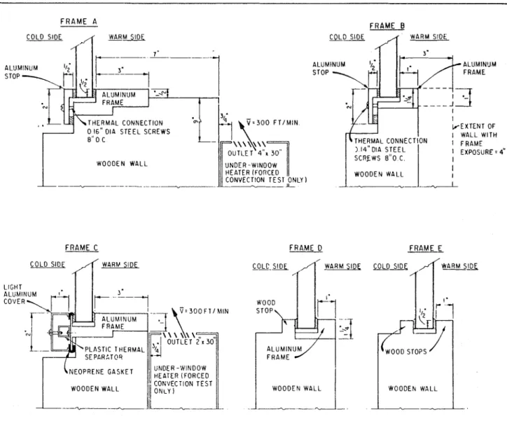
The five frames investigated are shown i n Fig. 5. Frames A and B were of similar construction and consisted of inner and outer aluminum members held together by steel screws. Frame C was also aluminum but the thermal separation between warm and cold frame members occurred outside the outer glazing stop. Frame D consisted of an inner aluminum member and an outer glazing stop of wood. Frame E was made of wood.
The configurations listed in Table II were investigated. The heater con- figurations for the forced convection conditions are shown in Fig. 5.
Surface and edge temperatures were measured along the vertical centre line of the inner or warm pane. The inside frame temperature was measured adjacent t o the edge of the sealed unit at the sill.
The glazing materials and glazing methods used in the study are ex-
plained in Fig. 6. The "butyl" glazing seal represented seals having a relatively low thermal resistance. A thin (1116 in.) neoprene face-shim plus sealant had thermal characteristics similar t o "butyl" seal. The ribbed "vinyl" seal represented seals having a
relatively high thermal resistance. Its behaviour was similar t o that of a ribbed or hollow compressible gasket of neoprene.
The glazing designations are re- levant only t o metal frames; they refer to the thermal connection between the sealed unit and the warm side of the frame. The glazing method with a high-resistance seal on the cold side and a low-resistance seal on the warm side would tend t o raise the edge temperature of the inner pane and is, therefore, designated the "favourable" method.
The measured inside-frame index, the bottom-edge index, the mean-pane index and the breakage potential of the inner pane are listed in Table II. The inside surface temperature profiles for a select number of configurations are shown in Fig. 7.
Glass Type
The temperature profiles of the clear and reflective units obtained under identical conditions are com- pared in Fig. 7a.
Due t o the higher air-space resist- ance of the reflective unit, i t s
mean-pane index was higher than that of the clear unit by 10, but the edge indices of the two units were nearly identical. The breakage potential of the reflective unit was, therefore, greater than that of the clear unit by 11 for the same condition of instal- lation.
Glazing Method
The edge temperatures of the clear unit in Frame A were measured with unfavourable, neutral and favourable glazing methods. Comparable results for the reflective unit were obtained in Frame B. For the clear unit, the breakage potential with the favourable glazing method was 17 less than that with the unfavourable method. The breakage potential of the reflective unit with favourable glazing was approximately equal t o that of the clear unit with neutral glazing.
Thermal characteristics o f frame (re- flective unit only)
The favourable glazing scheme caused the glass-edge temperature t o approach the inside-frame temper-
ature, and any change that affected the latter had a similar effect on the former.
The frame and glass-edge temper-
atures in Frame C were lower than
those in Frame B even though both
frames had the same inside exposure (4 in.). The low temperatures o f
Frame C may have resulted because
heat was lost from the frame t o the outer, as well as t o the inner, pane.
The frame and glass-edge temper-
atures in Frame D were relatively high
owing t o the high thermal resistance of
t h e o u t e r glazing stop. The
breakage-potential value (26) obtained with an inside-frame exposure of 2-114 in. was comparable t o the values
obtained in Frames A and B with
much greater frame exposures.
Frame E had a high-resistance
glazing stop on both sides of the sealed unit. The breakage potential of 40 was
similar to that obtained with neutral glazing in an aluminum frame, and was
greater than that obtained with
favourable glazing in a well designed aluminum frame.
Heater configuration and air-flow con- dition
The temperature profiles of the r e f l e c t i v e u n i t o b t a i n e d with
natural- and forced-convection air
flows in Frames A and C are shown in
Fig. 7.
An under-window heater provided the forced-convection air flow. The
heater outlet was located 7 in. from
the inner pane and 9 in. below the sill
of Frame A, and 4 in. from the inner
pane and a t sill level of Frame C. The
air discharge velocity from the heater
was approximately 300 ftlmin. The temperature index of the discharged air was approximately 110.
The forced convection discharge for Frame A impinged against the inner pane near mid-height. The centre-pane temperatures were consequently raised more than the temperatures near the sill; breakage potential with forced
convection, therefore, exceeded
that with natural convection by
approximately 6.
The u nder-window heater for
Frame C was adjacent to the window
sill and provided forced-convection air flow over the sill frame-member as well as over the whole inner pane. The edge and mean-pane temperatures were
therefore, increased by the same
amount and the breakage potential with forced convection was the same as with natural convection.
EDGE H SIGHTLINE 0 GLASS EDGE
I.
l - f c , l o o
f w - f cFIGURE 4
TYPICAL INNER-PANE TEMPERATURE PROFILES
s e e - *ZUMMARY
Cold-weather breakage of sealed units occurs when the stress resulting from several causes exceeds the edge strength of the inner pane of glass. One major cause of breakage is the difference between the mean-pane temperature and the glass-edge temper- ature of the inner pane; this difference is designated the breakage potential. Breakage potential decreases as the mean-pane temperature is reduced and the glass-edge temperature is increased.
The current study investigated the effect and relative importance of several factors on breakage potential.
(1)
Frame design and glazing methodThese factors had the greatest effect on breakage potential. The breakage potential of a sealed unit in a metal frame was affected by the temperature of only the outer frame
when the unit was unfavourably
glazed, and by the temperature of only
the inner frame when favourably glazed; i t was not affected by frame temperature with neutral glazing.
The breakage potential with favour-
able glazing was 13 t o 17 less than
with unfavourable glazing, and approx-
imately 7 less than with neutral
glazing. With favourable glazing in a metal, frame, the breakage potential of a sealed unit decreased as the inner frame temperature increased.
The breakage potential of a sealed unit in a wooden frame was equal to that of a unit in a metal frame with neutral glazing.
(3)
Heater configurationBreakage potential was affected by the heater depending on the air dis- charge configuration and the glazing
method. When the under-window
heater discharged air uniformly against the sill and centre-pane regions of a sealed unit favourably glazed in a metal frame, the breakage potential was not increased over that with natural convection.
The breakage potential was increas-
ed by approximately 6, however, when
air was discharged against the
centre-pane region but not against the sill frame member.
(2)
Glass TypeThe breakage potential of a unit with a low-emissivity reflective coating
was approximately 10 greater than
(4)
Air-space thicknessthat of a clear unit. I t is, therefore, The breakage potential of 114 in.
very important when using reflective units was approximately 5 less than
sealed units to take advantage of the that of the 112 in. units owning to the
other factors that can reduce breakage lower centre-pane temperatures of the
potential. thinner units.
F R A M E A C O D I D WARM SIDE I ' - --- - - - - 4 ALUMINUM
1 1
t - - ~ ' - ~
h - .1
1
hk
ALUMINUMI ' - ~ ~ f
d
0 16" DIP STEEL SCREWS WOODEN WALLIll
UNDER -WINOOW HEATER lFORCED11
CONVECTION TEST ONLY lFRAME C
COLD SIDE WARY SIDE LIGHT
FRAME
- .-
WOODEN WALL
(1
:",;::"ION TEST1
----
I[---
F R A M E B COLD SIDEA
FRAME 01
WOODEN WALL I---
I
-.--.-
I FRAME E--
RIBBED V I N Y L '1; EDGE COVER T H E R M A L CONDUCTANCE
,
B U T Y L>
V I N Y L ( A ) G L A Z I N G D E T A I L S U N F A V O U R A B L E COLD S I D E BUTYL ( 8 ) GLAZING METHODS WARM S I D E VINYLFIGURE
6 G L A Z I N G CONFIGURATION
WARM VlNY L V I N Y L N E U T R A L V I N Y L B U T Y L FAVOURADLE I =I-tc
x,oo
Ir-tcFIGURE 7 INNER-PANE TEMPERATURE PROFILES .-.COI - 4
(5) Edge design of glazing units For those sealed double-glazing units having organic seals, the breakage potential was affected by as much as 4 by the seahnt thickness between
spacer and glass; the breakage
potential was less with greater sealant thickness.
The breakage potential of a unit with a protective metal surround was
at most 3 greater than that of the same
unit with no surround. I t appears that no significant improvement in break- age potential can be effected by changing the edge construction from
those currently used, unless perhaps, a radical change is made.
REFERENCES
1. Brown, W. P.,
K.
R. Solvason, andA. G. Wilson, A unique hot-box
cold-room facility. ASHRAE Trans.,
V O ~ . 67, 1961, pp. 561-577.
2. Christensen, G., W. P. Brown, and
A. G. Wilson, Thermal performance of
idealized double windows, unvented. ASHRAE Trans., Vol. 70, 1964, pp. 408, 418. T A B L E 11 INSIDE S U R F A C E T E M P E R A T U R E P E R F O R M A N C E A T S l L L (Indic 2 s ) WS EXPOSURE = F R A M E S U R F A C E E X P O S E D TO WARM S I D E AIR (In. / f t of F r a m e Width) F R A M E A F O R C E D CONVECTION AIR FLOW ( U n d e r - Window H e a t i n g ) I ( m e a n ) NATURAL CONVECTION AIR F L O W ( R e m o t e H e a t i n g ) C l e a r U n i t ; WS e x p o s u r e = 3;"; U n f a v o u r a b l e glazing N e u t r a l glazing F a v o u r a b l e glazing R e f l e c t i v e Unit; WS e x p o s u r e = 3;"; I F R A M E B, R e f l e c t i v e unit WS e x p o s u r e = 2?, Unfavourable glazing N e u t r a l g l a z i n g F a v o u r a b l e glazing WS e x p o s u r e = 4", F a v o u r a b l e glazing F R A M E C , R e f l e c t i v e unit F a v o u r a b l e glazing, WS e x p o s u r e = 4'' F R A M E D , R e f l e c t i v e u n i t F a v o u r a b l e glazing WS e x p o s u r e = 2:" F R A M E E. R e f l e c t i v e unit N e u t r a l f r a m e I ( e d g e ) I ( m e a n ) : e d g e ) ( 72 72 7 2 72 7 2 7 2 7 2 I ( f r a m e ) A I ( m e a n - e d g e ) I f r a m e ) 2 6 33 39 4 5 39 4 6 3 2 A I ( m e a n - e d g e ) 4 6 4 8 4 6 5 3 4 2 5 6 3 8 4 6 3 9 3 3 27 3 3 2 6 4 0 83 5 0 5 5 3 3