A Comparison of High Temperature Fuel Cells and
Gas Turbines for Expansion of the MIT Cogeneration
Plant
By
Headley Stewart Jacobus
Submitted to the Department of Mechanical Engineering in Partial Fulfillment of the Requirements for the Degree of
Bachelor's of Science in Mechanical Engineering At the
Massachusetts Institute of Technology June 2005
©( 2005 Headley S. Jacobus. All rights reserved The author hereby grants to MIT permission to reproduce and to distribute publicly paper and electronic copies of this
thesis document in whole or in part
A Signature of Author:
I
Certified by: VI,I...
, - - v _- ,, ,//
DepartWment-oIMechanical Engineering-a~ ~May
6, 2005
-- 1 ~ ~ ~ 'I ' ~ John B. HeywoodSun Jae Professor of Mechanical Engineering Director, Sloan Automotive Lab 'Thesis Supervisor Accepted by:_.
Ernest G. Cravalho Professor of Mechanical Engineering Chairman, Undergraduate Thesis Committee
MASSACHUSETTS INSTITUTE OF TECHNOLOGY JUN 8 2005
LIBRARIES
-.... J ... I 1.Table of Contents
A COMPARISON OF HIGH TEMPERATURE FUEL CELLS AND GAS TURBINES FOR EXPANSION OF THE MIT COGENERATION
PLANT...1
Table of Contents ... 2 Table of Equations ... 3 Table of Figures ... 3 Abstract...4 Acknowledgem ents ... 5 Introduction6Introduction ... 6Introduction6 Background...7 Methods... 12Gas Turbine Feasibility Study ... 15
Research R16Research Results ... 16
UTC Power17UTC Power ... 17UTC Power17 Siem ens W estinghouse ... 20
Fuel Cell Energy ... 23
Initial Model to Compare Fuel Cells with Solar Taurus 60 ... 26
Model of Fuel Cell Plants with Duct Firing ... 29
Third Fuel Cell Modelfor Preheating HRSG Feedwater ...32
CO22Emissions38 Emission38... 38CO Conclusion ... 41
References44References ... 44References44
Appendix A45Appendix A ... 45Appendix A45
Appendix B47Appendix B ... 47Appendix B47
Table of Equations
2H2 = 4+ + 4e Eq. 1 18
0° + 4e- + 4- ::= 2H20O Eq. 2 18
CH4+ H20 + Heat = CO + 3H2 Eq. 3 18
CO + 1120 = C02 + H2+ Heat Eq. 4 18
02+ 4e- = 202- Eq. 5 21
2H2+ 20A- = 220 + 4e- Eq. 6 21
2C0 + 20 = 2C02 + 4e- Eq. 7 22
02 + 2C02 + 4e = 2C032- Eq. 8 24
2H2 + 2CO32 - = 2H2O + 2C02 + 4e- Eq. 9 24
2C0 + 2C03 2
-= 4 C02 + 4e- Eq. 10 24
Q- W= m * (h'.-ho0 Jd Eq. 11 27
q = (W + Q)/(m * Hna,ra,, gas) Eq. 12 28 (Weiectrc)j( and (;7/(Welectri)Jfidlpower GT * GT electrical work Eq. 13 34
(Q,hermaFlt'. and ;('Qthermadfill powerG l'* GTthermal output Eq. 14 34
C02kg/MJ =fuelflowrate (kg/sec) * 12/(12+3.8+ 1.4) * 44/12 / MWproduced Eq. 15 40
Table of Figures
Figure - Cogeneration Plant Energy Diagram 8
Figure 2 - Energy Diagram for UTC Pure Cell 200 19 Figure 3 - Siemens Westinghouse Energy Flow Diagram 22
Figure 4 - Exhaust recirculation in MCFC 25
Figure 5 - MCFC Energy Flow Diagram 26
Figure 6 - Model I Energy Flow Diagram 27
Figure 7 - Model 2 Energy Flow Diagram 29 Figure 8 - UTC Duct Firing Energy Flow Diagram 31
Figure 9 - GT/Fuel Cell Hybrid Diagram 34
Figure 10 - UTC Model with Gas Turbine 37
A Comparison of High Temperature Fuel Cells and Gas
Turbines for Expansion of the MIT Cogeneration Plant
By
Headley Stewart Jacobus
Submitted to the Department of Mechanical Engineering in Partial Fulfillment of the Requirements for the Degree of
Bachelor's of Science in Mechanical Engineering
Abstract
In the past decade the MIT campus has grown by leaps and bounds. New buildings such as the Zesiger Sports Center, Stata Center, Simmons Hall, and Sidney-Pacific Street Dorm are only some of the buildings erected in the past decade. Such extreme campus growth means that the MIT campus is quickly outstripping its ability to produce steam and electricity. At the moment, MIT's campus peak demand is 31 MW of electricity and 372,282 lbs/hr of steam' yet the MIT cogeneration plant only produces 21 MW of power and 230,000 lbs/hr of firm steam production2. In addition to this desire to satisfy its own energy requirements, MIT must also minimize greenhouse emissions from the campus.
In 2004 MIT completed a feasibility study to expand the campus cogeneration plant by installing two new gas turbines and Heat Recovery Steam Generators. I have endeavored to study the feasibility of using fuel cells as a replacement to these gas turbines. Specifically I examined UTC Power's PureCellTM 200, Siemens
Westinghouse's SFC 200, and Fuel Cell Energy's DFC 3000. These three fuel cells represent a range of fuel cell technology available for commercial use now or within the next two years. All three fuel cells could be viable for distributed cogeneration around campus, but do not seem suitable for use in an expansion housed solely in Building 41. All three fuel cells require large footprints to produce the 11 MW called for in the planned plant expansion. These three fuel cells could be made more attractive for the MIT cogeneration plant by augmenting their thermal production with either direct natural firing in the fuel cell exhaust or coupling the fuel cell with a gas turbine. Fuel cells will increase the electrical efficiency of the gas turbine and, depending on the fuel cell, may also increase the overall efficiency of the gas turbine. Increasing overall efficiency will result in decreased CO2emissions and decreased fuel costs for MIT.
Thesis supervisor: John B. Heywood
Title: Sun Jae Professor of Mechanical Engineering Director, Sloan Automotive Lab
Haskell (2004) page section A
Acknowledgements
The nature of this thesis was more commercial and market research rather than experimental. Much of the data that I depended on was found outside of MIT labs, and so I am extremely grateful to those that furnished me with the information that I needed to continue with my thesis. I would like to thank Steven Lanou at the Environmental Health and Safety Management Office, who acted as a conduit through which I could access the campus Central Utility. Peter Cooper, who is manager of Sustainable Engineering and Utility Planning, was invaluable by giving me access to the Cogeneration Plant Expansion report. Roger Moore and Seth Kinderman helped me out when I was floundering and needed very specific data on the Cogeneration plant. I would also like to acknowledge my industrial contacts from which I was able to get the information on fuel cells stated in this thesis: Chris Forbes from Siemens Westinghouse, Bill Snyder at FCE, and Joe Staniunas from UTC Power. These engineers endured weeks of almost daily phone calls while I was trying to gather information. I would especially like to thank my thesis advisor Professor John B Heywood, who guided me through this thesis from its inception in the summer before my senior year to its competition. I leave my last thanks to Karla Stryker, who I am deeply indebted to for helping me schedule innumerable weekly meetings with Professor Heywood.
Introduction
Widespread use of fossil fuels started in the early 19th century with the ubiquitous
use of coal to power the Industrial Revolution. Coal was eventually replaced by petroleum, but the resulting release of greenhouse gases did not stop. Greenhouse gases are defined as any gases that reflect energy radiated by the earth back towards the earth. This list includes many more environmentally harmful chemical compounds than carbon dioxide, such as methane and NO, but our release of carbon dioxide far outstrips any other greenhouse gases and so it is the largest contributor to global warming.
Carbon dioxide remains in the atmosphere for 100 years, so steps must be taken immediately if the amount of carbon dioxide is to be stabilized in the atmosphere. The Kyoto Protocol in 1997 was the product of the global movement to control greenhouse gases. The treaty obligated some of the largest CO2 emitters to cut carbon dioxide
emission to 5-8 percent of 1990 levels by 2010. To complicate matters, the world's energy usage, i.e. CO2emission, is rising. The treaty did not bind developing countries to
carbon dioxide cuts, but countries like India and China are consuming huge amounts of energy in order to increase the quality of life for their citizens and move their economies forward. The decreases needed in carbon dioxide emissions can only be realized with new technologies that achieve higher fuel efficiencies than our current fossil fuel technology.
The Kyoto Protocol indirectly binds MIT to decrease its emissions over the next five years. Like the world around it, MIT must decrease its greenhouse gas emissions despite undergoing a tremendous amount of growth. Fuel cells are devices that could
potentially help solve MIT's unique energy requirements. Medium and high temperatures fuel cells operate at temperatures high enough to produce high quality steam (150 to 1000 Celsius) and have electrical efficiencies approaching fifty percent. Contrast this to the gas turbine currently installed in the Cogeneration Plant that operates at twenty-four percent electrical efficiency. Some of these fuel cells run so hot that they are able to internally reform natural gas into hydrogen and carbon gases which the fuel cell then oxidizes, so the natural gas lines that currently feed the cogeneration plant can still be utilized.
Through potential increases in fuel efficiency, fuel cells have the ability to cut the amount of carbon dioxide emitted by the MIT campus. They are also a step in the direction towards a hydrogen economy that would release zero harmful emissions. At the moment fuel cell technology is still a baby compared to the hundred-year-old fossil fuel technology that is currently used, so fuel cells are not as well developed as fossil fuel technologies. As a result it is difficult to assess if one technology is inherently more appropriate for usage in the expansion of the MIT cogeneration plant. It is my hope to compare the efficiency, carbon emissions, and fuel costs for a fuel cell with that of a gas turbine system, which is the current method to produce heat and power for the MIT campus.
Background
The current MIT cogeneration plant produces roughly 21 MW of electricity and supplies 230,000 lbs of steam an hour for the entire MIT campus3. The steam plant utilizes the energy in the high temperature exhaust of the gas turbine to raise steam for a
substantial increase in overall plant efficiency. While recent research shows that the gas turbine has an electrical efficiency of twenty-four percent , the entire plant is able to recover about eighty percent of the energy content of the natural gas in the form of either electricity or steam. Additional boilers that burn #6 oil or natural gas can be brought online if greater quantities of steam are needed to heat or chill the campus. A diagram of the cogeneration plant can be seen in Figure 1.
SAkV AI 2AKVWbWd1 s LSn
Figure 1 - Cogeneration Plant Energy Diagram
There is also the option to purchase power from the outside power grid, if the campus electricity demand is more than what the gas turbine can supply. This is becoming more the rule rather than the exception, as MIT currently needs to purchase twenty percent of its annual electricity from the outside municipal grid5. As a result of MIT's increasing demand for utilities and pressure to reduce CO2emissions, MIT has to seriously consider the best way in which to expand the cogeneration plant.
4 Groode (2004) page 60 5 Groode (2004) page 15
Fuel cells and gas turbines both produce power from fuel, but that is where the similarities stop. While internal combustion engines require complex moving parts and a working fluid, these are not found in fuel cells. Also the temperatures in fuel cells are considerably lower, even in the high temperature Solid Oxide Fuel Cells (SOFC). Fuel cells can run anywhere from 400 to 1500 degrees C cooler than engines depending on the kind of fuel cell used. This reduction in operating temperature reduces emissions of the system. Fuel cells have extremely low NOx emissions for this reason. The way in which engines and fuel cells oxidize fuel is also very different. Most engines will bur a hydrocarbon fuel with an oxidizer to release a large amount of thermal energy. Fuel cells will peel electrons off of hydrogen through the use of catalysts, shuttle the ions through the fuel cell electrolyte, and then combine the electrons and hydrogen with oxygen to create water. While engines need a generator to convert motion into electricity, fuel cells convert the energy in fuels directly into electricity. The higher electrical efficiency of fuel cells yields more electrical energy produced per unit of CO2released.
There are several different kinds of fuels cells that are available, but most are unsuitable for cogeneration applications. The lightweight Polymer Electrolyte Material fuel cells (PEM), which are being developed for automotive use, are designed to run at only 80 degrees Celsius. While companies like Ballard Power Systems, have developed stationary cogeneration plants using PEM technology; they are of limited usefulness for most cogeneration applications. They are only capable of rejecting heat to a hot water loop at relative low temperatures. In addition, the low lifetime and high materials costs associated with these fuel cells are qualities not generally suited for stationary power applications. Alkaline fuel cells are the oldest fuel cells and were developed for
powering NASA space systems, but they are so sensitive to catalyst poisoning that they must be fueled with pure oxygen and hydrogen. Neither of these fuel cells would be appropriate for supplying steam and electricity to the MIT campus because they either lack robustness or lack high enough temperatures to generate large amounts of steam.
However, there are three types fuel cells that do have qualities that make them suitable to cogeneration applications. Solid Oxide Fuel Cells were developed in an effort to run a fuel cell at temperatures hot enough so that cheaper nickel catalysts could replace expensive noble metal catalysts. Most SOFC run in the neighborhood of 1300 K. In order for the internals of the SOFCs to withstand the high temperatures they are subjected to, SOFCs have ceramic electrolytes instead of liquids, gels, or delicate polymers. While high temperatures are of little consequence to the ceramics used to make the anode, cathode, and electrolyte; housing the fuel cell becomes a problem. The only metals that can maintain strength at these high temperatures are expensive super-alloys. Current research is aimed at lowering the operating temperature of SOFCs so that super-alloys are not necessary., yet still run the cell hot enough to use nickel catalysts instead of noble metals. One of the benefits of SOFCs is that the high operating temperature allows internal reforming of hydrocarbons. Hydrogen is stripped from the hydrocarbon molecules when it comes in contact with catalysts found in the cathode of the SOFC. This means that SOFC plants can be supplied by existing natural gas lines. These fuel cells can turn about half the energy content of the fuel into electricity, which is double the efficiency of the gas turbine currently installed in the MIT cogeneration plant. Even though SOFC can be expensive due to their high operating temperature they are ideally designed for stationary cogeneration.
Molten Carbonate Fuel Cells could be very attractive for cogeneration because they operate at about 650 Celsius, hot enough to produce pressurized steam. Of the three fuel cells examined in this thesis, MCFC are the least developed commercially. One peculiarity of MCFC is that the electrochemical reaction consumes CO2 at the cathode
and produces CO2at the anode. This means that CO2must be scrubbed from the exhaust
gas and injected into the fuel stream. In practice this is done by recycling anode exhaust back through the cathode, a procedure that is already done in other types of fuel cells to preheat the air about to enter the cathode. As a result of the elevated temperatures and the aggressive chemicals contained in the fuel cell carbonate electrolyte, MCFC tend to suffer from excessive corrosion. MCFC use stainless steel for the bipolar plates that separate a single fuel cell unit from the next, which can be quite costly6.
Development of Phosphoric Acid Fuel Cells started in the 1970s, before most other fuel cells, so PAFC technology is more mature than SOFC or MCFC technology. Of the three fuel cells that are viable for cogeneration PAFC is the most widely distributed. For example a 1 MW fuel cell system was installed in the Anchorage post office depot recently. This type of fuel cell operates at 190 C, so it is able to raise steam for certain cogeneration applications, but it is not able to internally reform its own fuel. If this type of fuel cell were to be run off of hydrocarbons, the fuel must be externally reformed. This is because the fuel cell must still use noble metals to catalyze the oxidation reaction and if any CO or CO2 enters the fuel cell these metals may be
poisoned, rendering the catalyst permanently ineffective. Some of the energy in the fuel is lost due to the reforming process, which tends to decrease the efficiency of the fuel cell, but this is less of a concern in cogeneration applications because the reformer
becomes a source for high temperature heat. The phosphoric acid fuel cell has an electrical efficiency of about 40 percent, but when waste heat is captured, the total fuel energy usage can be as high as 80 percent.
Methods
There was four different phases through which this thesis advanced. The first stage was preliminary work that included reviewing fuel cell basics. In reviewing fuel cells it was important to note the capabilities of certain fuel cells to see which are viable
for cogeneration. I also conducted market research on which companies supply appropriate fuel cell technology. The most obvious hurtle that a fuel cell must clear to be affective for cogeneration is to operate at temperatures high enough to raise steam. Other hurdles include durability, expense, and propensity for catalyst poisoning. I have found that many fuel cell designs are not appropriate for our application. The best fuel cells for cogeneration are Solid Oxide Fuel Cells, Phosphoric Acid Fuel Cells, and Molten Carbonate Fuel cells.
The second phase was to establish the design requirements that must be met with the cogeneration expansion. Is it more important to increase the availability of electricity or steam? The higher electrical efficiencies in a fuel cell generally means that the fuel cell is able to produce more electricity from natural gas, but the electricity comes at the expense of steam production. Is MIT looking to centralize the new cogeneration expansion or is it possible to distribute the power supplies around campus? Fuel cells are similar to batteries in that one can stack fuel cells in series to produce more power. This means that in order to get several hundred kilowatts or a couple megawatts, it takes many fuel cell modules. The footprint needed to accommodate the fuel cells might be
prohibitive if they need to be centrally located. For this reason I have looked into the power produced by a fuel cell divided by its projected footprint. It is important to note that as fuel cell systems become larger, the balance of plant (BOP) modules can be consolidated into more space efficient units and the power-footprint ratio will increase with power rating. So my method of adding the footprints of smaller fuel cell substacks together to estimate the footprints for larger fuel cell power plants is a conservative estimate, but I am hoping to give an impression of the order of magnitude needed for the footprint of a fuel cell power plant.
If the fuel cells were to be distributed throughout the campus, then it would be easier to find the footprint needed for one fuel cell here or there despite the low power-footprint ratio. Fuel cells located close to the buildings they are heating would also gain from less heat loss to the environment when piping steam to where heat is needed. Then again, the benefits of distributing fuel cells around campus may be offset by the need to route natural gas piping to each fuel cell. Fuel cells are known to produce steady voltages that do not fluctuate with the frequency of the generator (as a result of not having a generator.) This could be an important benefit for labs doing research on sensitive electronics. Fuel cells would certainly be very useful if steady voltage was a design requirement. MIT has already given some thought to the cogeneration plant expansion, but so far no one has seriously examined the capabilities of fuel cells and applied them to MIT's utility needs7. Once all these needs are known, then it will be possible to understand what must be done in order to maximize efficiency and produce a
performance and cost forecast.
The third part of my thesis was to collect data from both the MIT cogeneration plant and from companies that make fuel cells. Data for the gas turbine in the MIT cogeneration plant is available for the six years, from 1998 to 2003, and has already been examined extensively 8. This data will be the foundation of any models that I make in
order to predict future performance of the existing gas turbine. Several companies have installed SOFC, phosphoric acid fuel cells, and MCFC demonstration plants over the US. The function of these plants is to provide data to companies that are hoping to build larger viable fuel cell plants. I was able to collect enough data from companies that operate these plants to generate several thermodynamic models for the three fuel cells studied in this thesis. This involved extensive contact with UTC Power, Siemens Westinghouse, and Fuel Cell Energy.
The fourth stage of my thesis was closely linked to gathering data. I analyzed the data I collected and created models to predict the possible performance of the three commercial fel cells I have chosen. I created three models that are helpful in comparing fuel cells with the gas turbine selected for installation into the plant expansion9: one where the fuel cell will directly raise steam, and a second where the fuel cell is augmented with natural gas firing to achieve comparable steam production rates as the gas turbine, and a model where a fuel cell is integrated with the existing gas turbine installed in the MIT cogeneration plant. Values I will pay particular attention to are: required footprint, thermal output, total efficiency, steam mass flowrate, and fuel consumption and cost.
8 Groode (2004)
The conclusion of the thesis will give my feelings for the viability for fuel cells to be incorporated into the MIT campus utilities. I will recap the performance comparison of fuel cells and gas turbines as shown by the models I created. I will also include any outstanding design criteria that were set by Physical Plant. I note any differences in CO2
emission by one system or another. I also hope to include such useful information such as total efficiencies and possible changes to the current system that may save Physical Plant money.
Gas Turbine Feasibility Study
In 2004, R.G. Vanderweil Engineers, NC of Boston, MA completed a feasibility study for MIT covering an eleven-megawatt expansion of the campus cogeneration plant. Two Solar Taurus 60 gas turbines capable of producing 5.5 MW each and up to 105,000 lbs/hr of steam with supplemental firing'° were proposed for the expansion. When compared to the current practice of purchasing peak power and peak steam from municipal utilities, it was calculated that the cogeneration plant expansion would represent a net savings of $69,000,000 over twenty-five years. The capital cost of the cogeneration plant expansion was estimated to be $40.6 million
The study used hourly data from the campus's heating and electricity demands and extrapolated the data into the future. The study also took into account the planned completions of the Brain and Cognitive Science Building (2005), the Cancer Center (2008), Sloan School expansion (2010), and the Media Lab expansion (2012) in predicting the increasing campus demand. In addition to adding the expected jump in utilities when these buildings open up, it was assumed that both electric and steam
demand would increase by 3.5 percent between 2005 and 2008. From 2009 to 2031, it was assumed that electricity and steam demand would increase by 1.5 percent. The fuel prices used in calculating the cost analysis were prices reflecting long-term predictions from the natural gas industry. The study took into account that the availability of the gas turbines and boilers will not be 100 percent. It was expected that the existing gas turbine either be unexpectedly or routinely offline for one month and two additional weeks every year, the boilers would be down for one month and four separate weeks over the year, and the new gas turbines would be offline for two weeks each year.
Research Results
I researched three different fuel cells for their potential viability for cogeneration. Fuel Cell Energy sells the largest fuel cell plants, up to 2 MW, and they utilize a molten carbonate electrolyte2. I analyzed the DFC 3000 which produces 2200 kW of electrical energy and 1777 kW of thermal energy. Siemens Westinghouse will soon bring to market the SFC 200, which is a solid oxide fuel cell. The basic unit produces 125 kW of electrical energy andl 15 kW of thermal energy. The last fuel cell I looked at was United Technology's PureCellTM 200. It is a phosphoric acid fuel cell that produces 200 kW of electricity and 264 kW of thermal energy.
The gas turbine expansion feasibility report recommends using the Taurus 60 gas turbine which produces roughly 5.5 MW of electricity and 25,000 lbs/hr of steam. With additional direct firing it is possible to produce up to 105,000 lbs/hr of steam per gas turbine. To compare the different fuel cells with each other and the Taurus 60, I
" Haskell (2004) executive summary page 10
estimated the size and energy outputs of a fuel cell plant that would produce roughly 5.5 MW of electricity as well.
UTC Power
The PureCellTM 200 is a renaming of UTC Power's PA25C fuel cell; a product of one of the oldest fuel cell development programs as well one of the most widely available fuel cells'3. It is a 200 kW phosphoric acid fuel cell developed by UTC Power, a division of United Technologies. It produces about 264 kW in thermal energy. Each stack has a footprint of 2.36 square feet, which equates to 847 watts per square foot. It would take 27 subunits to produce a 5.4 MW electrical plant. This plant would also produce 7 MW of thermal energy and would have a footprint of 6372 square feet. The cost of each 200 kW stack is about $900,00014.
Phosphoric acid fuel cells generally operate above 150 C, and the temperature of the system must be carefully controlled since if the fuel cell were to heat up to over 220 C the phosphoric acid electrolyte will begin to break down15. While thermal energy at 190
C will boil water at atmospheric conditions, the exhaust coming out of the fuel cell is at a lower temperature than the fuel cell operates at. The PureCellTM 200 offers two temperature options, one where the entire heat load is rejected at one temperature (140 F) and a second option where half the heat is rejected at a higher temperature (250 F) and half at the original temperature (140 F). Unfortunately the MIT steam loop is a pressurized loop that operates at 450 F, so the phosphoric acid fuel cell is not able to raise
13 Larminie and Dicks (2004) page 186
14 Hooders (2003) page 8-14 15 Hooders (2003) page 8-3
steam for the MIT steam circuit. As a result, I was forced to modify each one of my models to take the PureCellTm 200's tricky heat rejection into account.
The phosphoric acid electrolyte transfers protons from the anode to the cathode; the overall chemical reaction that occurs is the following:
Anode:
2H2 = 4H+ + 4e- Eq. 1
Cathode:
02+ 4e- + 4H+= 2H20 Eq.2
It is important to note that the PAFC does not oxidize carbon monoxide like the Molten Carbonate and Solid Oxide Fuel Cells mentioned immediately following this section. Carbon monoxide will poison the platinum catalyst and a PAFC is only tolerant of CO
16
concentrations of less than 1 percent . If a fossil fuel is to be used to produce hydrogen then carbon monoxide will almost always be present and reforming will be necessary. Reforming is described by this equation.
CH4 +4 H20+ Heat = CO + 3H2 Eq. 3
In fuel cells that do not normally operate at temperatures above 500 C, this heat must be supplied by burning extra fuel. Even after the reaction described in Eq. 3 occurs, the carbon dioxide concentration must be reduced even further. In practice this is done with the exothermic water-gas shift reaction:
CO+
1 2 0 =CO
2+H2+Heat
Eq.4
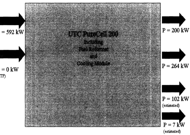
Based on information supplied from UTC power, I was able to produce a First Law energy balance for the PureCellTM 200. I used the HHV of natural gas17to calculate both the electrical and total efficiencies of the PAFC. The fuel cell has an electrical efficiency of 34.6 percent and a total efficiency of 80.2 percent. Please refer to Figure 2 to see the energy into and out of the control volume around the power plant.
P = 200 kW P = 264 kW P = 102 kW (estimated) P = 7 k (estimated
Figure 2 - Energy Diagram for UTC Pure Cell 200
The temperature of the air exiting the cooling module is known to be about 40 F above ambient temperature, but the exact massflow is unknown; the energy carried away from the fuel cell by the cooling air was estimated to be about 7 kW.
Siemens Westinghouse
Siemens Westinghouse is developing a solid oxide fuel cell for commercial release in 20(}7 called the SFC 200. Their product is a 125 kW stack that also produces 115 kW of thermal energy to be released to a hot water loop. Each stack unit requires approximately 375 square feet, so the stack is able to produce 333 W per square foot. A 5.4 MW power plant made from 44 125 kW SOFC stacks would also produce about 5 MW of thermal energy which could be used for campus heating. The footprint of all the subunit stacks in the power plant alone would be 3069 square feet, but this number does not include the balance of plant modules such as heat exchangers, electricity conditioners, etc.
SOFCs 18 are an attempt to build a fuel cell using cheaper and more tolerant
electrolytes and electrodes. Most SOFC electrolytes are made with yttria-stabilized zirconia with nickel catalysts instead of expensive noble metals. In order to have the electrochemical reaction on the anode occurring at a suitable rate, SOFCs must operate at high temperatures on the order of 1000 C. The rate at which the zirconia can transport 02- ions drops precipitously at temperatures lower than 1000 C.
There are many advantages and some disadvantages to this high operating temperature. The most notable advantage is that the fuel cell is hot enough to able to reject heat to steam production for a bottoming cycle or cogeneration. I have been told that the SFC 200 is being developed to reject heat to a hot water loop, but that it would be possible for customers to work with Siemens Westinghouse to link the fuel cell to a heat recovery steam generator9. A second advantage of the SOFC is the cheaper and more
18 Solid Oxide Fuel Cell '9 HRSG
robust electrolyte and catalyst material, but the cost savings are tempered by the need for more costly heat resistant metal housings. The high operating temperature also means that SOFC have extremely long startup times. This means that the fuel cell is more appropriate for stationary applications rather than intermittent backup power. MIT imports its peak power demand from the local Cambridge utility, NSTAR, so the campus does not need standby auxiliary power. There is ongoing research here at MIT and at other universities trying to increase the ion transport rate of the SOFC electrolyte at lower temperatures, thus lowering the operating temperature and allowing the use of cheaper housing metals.
Greater fuel tolerance is also a large benefit for using SOFCs. They are able to oxidize both hydrogen and carbon monoxide to produce electricity. SOFCs and, as I will mention later. the Molten Carbonate Fuel Cell are also capable of internal fuel reforming where steam and methane are mixed in the presence of the proper catalyst, usually nickel, to produce hydrogen. This is the same reaction as Eq. 3, which must occur outside of the PAFC. This endothermic reaction is able to use heat from the fuel cell, helping to moderate the temperature of the fuel cell. Internal reforming will continue to be attractive with natural gas powered fuel cells until there is a large readily available source of hydrogen for distributed power production. The electrochemical reactions at the electrodes are as follows for SOFC:
Cathode:
02 + 4e = 202- Eq. 5
Anode (for hydrogen fuel):
Anode (for Carbon monoxide):
2CO + 202- = 2CO2+ 4e Eq. 7
A quick inspection of Eq. 7 shows that CO2 is a byproduct of the electrochemical reaction
that produces electric power. While SOFCs are not zero emission power plants, but it is hoped that with the higher efficiency of the fuel cell (in the neighborhood of 47 percent for the SFC 200) SOFC produce fewer kilograms of CO2 per unit of useful energy
produced.
A thermodynamic model of the system shows that the SOFC fuel cell has an electrical efficiency of 40.9 percent and a total efficiency of 78.5 percent. To see the energy flows into and out of the cell please refer to Figure 3
P = 125 kW
P= 115 kW
P=34 kW
The difference between the energy out and in is 31 kW which represents about 10 percent of the energy carried in by the natural gas. This energy loss is assumed to be heat loss through the fuel cell vessel to the atmosphere.
Fuel Cell Energy
The DFC 3000 is a 2.2 MW molten carbonate fuel cell plant. Within the plant are two fuel cell modules that each produce 1.1 MW. In addition to the fuel cell modules, each plant has: a module for conditioning the electricity, a fuel treatment module, a water treatment module, and a heat recovery module. In total the 2.2 MW plant has a footprint of 5700 square feet, or about 386 watts per square foot. One DFC 3000 would produce
1.78 MW of thermal energy.
Molten carbonate fuel cells have an electrolyte of molten alkali metal carbonates that are able to transport the ion C032- from the cathode to the anode at temperatures
above 600 C. This leads to one of the MCFC's largest drawbacks, the high temperature and aggressive electrolyte leads to corrosion problems within the cell. Expensive materials such as stainless steel bipolar plates must be utilized20, but this temperature allows the use of nickel catalysts similar to those found in the SOFC. Also similar to the SOFC, the MCFC can internally reform fuel as it comes into contact with the catalysts on the anode. It should be noted, though, that the temperatures usually found in the MCFC are not high enough to completely convert all the natural gas into hydrogen and carbon monoxide. The pass-through fuel containing the un-reacted fraction of fuel is later combusted to preheat the cold air coming into the fuel cell. The electrochemical reactions that occurs at the fuel cell electrodes are:
Cathode:
02+ 2C0 2+4e = 2C0 32- Eq. 8
Anode (for hydrogen fuel):
2H2 + 2CO32-= 2H20 + 2CO2 + 4e- Eq. 9
Anode (for carbon monoxide fuel):
2CO + 2C032 = 4 C02 + 4e Eq. 10
It is important to note that CO2 appears in both the cathode and anode equations. Molten
carbonate fuel cells use the greenhouse gas as a carrier of ions across the electrolyte. As long as the CO2 is harvested from the exhaust stream and recycled back to the cathode,
there is no release of CO2 to the atmosphere. MCFC could potentially release no
greenhouse gases. The way DFC 3000 recycles CO2 from the exhaust gas is similar to
how other fuel cells choose to preheat their incoming air, but it involves cycling the exhaust from the anode through a burner.
A fraction of the natural gas that comes into contact with the anode is not electrochemically reacted. This is a result of the fact that the nickel reforming catalysts do not work s well at the relatively low temperature of 650 C as they do at the higher temperatures of SOFC. The exhaust from the anode contains CO2, steam, and a fraction of un-reacted natural gas. This anode exhaust gas is mixed with cold air headed for the cathode. This mixture is then sent to a combustor where the remaining fuel is burned, creating additional CO2. This process not only recycles the CO2 from the exhaust of the
of recycling CO2 from the anode to the cathode as well as combusting fuel does produce
a net gain of CO2 that is then exhausted to the atmosphere. Please see Figure 4 for a
diagram of the gas routing through the MCFC.
CO2 KT,-4 1 -,. Steam 1 Natural Ga in Cold Air
Cathode
-Heated Air A ;r CO2 co2 steam 2 SteamFigure 4 - Exhaust recirculation in MCFC
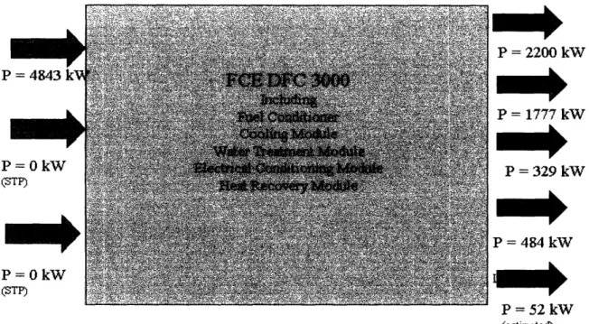
The theoretical electrical efficiency of the MCFC, should be higher than most other fuel cells by virtue of the electrolyte chemistry that yields a higher open circuit voltage. After doing a thermodynamic analysis on data I received from Fuel Cell Energy, I found that the DFC 3000 had an electrical efficiency of 45.4 percent and a total efficiency of 82.1 percent. Please refer to Figure 5 for details describing the energy flows into and out of the control volume around the power plant.
P = 2200 kW P= 1777 kW P = 329 kW P = 484 kW '1- I.-'1Y
r
- J KW (estimatecd)Figure 5 - MCFC Energy Flow Diagram
Initial Model to Compare Fuel Cells with Solar Taurus 60
The initial model I examine compares the three fuel cells described above to the gas turbine proposed in the MIT gas turbine feasibility study. The Solar Taurus 60, the gas turbine proposed for the expansion of the MIT cogeneration plant, can produce 5.5 MW of electricity and 25000 lbs/hr of steam. I calculate how a comparably sized 5.5 MW fuel cell power plants compare to Solar Taurus 60 in making steam without the help of duct firing2'. While I made electrical output the same for the gas turbine and all the fuel cells, the thermal output for each fuel cell varies so differences showed up in the
21 Duct firing is when natural gas is burned in the exhaust duct of the fuel cell to help boost the thennrmal performance of the fuel cell.
22
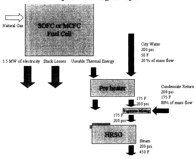
mass flowrate of steam the fuel cell is able to produce2 2. It should be noted that the UTC PureCellm 200 only rejects heat at 140 F and 250 F and is unable to raise the 450 F steam without the aid of duct firing. Therefore there is no initial model for the PureCellTM 200, but there will be a duct firing model discussed later. The unfired SOFC and MCFC models can be described by the figure on the following page.
Figure 6 - Model 1 Energy Flow Diagram
Natural Gas Natural Gas
City Water 200 psi
50 F
5.5 MW of electricity Stack Losses Useable Thermal Energy 20% of mass flow
It
Condensate Return 175 200 psi
200 psi 80% of mass flow
175 F
200 psil
Steam
4
200 psi 450 FTo calculate these states I used the Steady State Energy Equation:
Q - = m * (hn-ho.t) Eq. 11
22 Strictly speaking, no company advertised their fuel cell for generating steam, I am assuming that, given a
high enough operating temperature, it is possible to attach an HRSG to the fuel cell to harvest its thermal energy.
This equation assumes that velocity and potential energy terms are negligible. I would find the total efficiency through the following equation:
q = (W + Q)/(m * AHnaturai gas) Eq. 12
The Siemens-Westinghouse SFC 200 fuel cell is the baseline unit for a 5.5 MW system that also produces 5.06 MW of thermal energy for a total efficiency of 78.5 percent2 3.
This thermal energy is rejected at a temperature of 842 F, so there is no problem with the exhaust being too cool to generate steam. The mass flowrate that the fuel cell is able to sustain with this thermal output is 15,350 lb/hr of steam. The required footprint for the plant is 16,500 square feet, and the fuel cost would be approximately $1.917 million a
24
year4
The Fuel Cell Energy's DFC 3000 comes as a 2.2 MW units. In order to hold the electrical outputs of the Taurus 60 and other fuel cells constant at 5.5 MW, I have analyzed 2.5 units of the DFC 3000. Fuel cells are, by nature, modular, and the DFC 3000 is made of two fuel cell modules serviced by the balance of plant components. In fact, it is possible to buy a single fuel cell module from Fuel Cell Energy. The 5.5 MW plant would also produce 4.45 MW of thermal energy and has a total efficiency of 82.1 percent. This system could raise about 13,475 lbs/hr of steam for a yearly fuel cost of about $1.727 million. The footprint required for this fuel cell would be about 14,250 square feet.
23 When using natural gas's higher heating value of 50 MJ/kg
24 Using a fuel price of $0.004523 per MJ of natural gas calculated from average price charged to MIT
Model of Fuel Cell Plants with Duct Firing
The Solar Taurus 60 gas turbine can also be run with duct firing to generate a larger steam mass flow. This can be up to 105,000 lbs/hr of steam. I analyzed both the SFC 200 and DFC 3000 power plants' performance when aided by natural gas combustion to produce 450 F and 200 psi steam at this mass flowrate. The energy flow diagram for this model is given in the figure below.
Natural Gas> Natural Gas
City Water
200 psi f5 F
5.5 MW of electricity Stack Losses Useable Thermal Energy 20 % of mass flow
I "I
Condensate Return
1 F 75 200 psi
175 F 175 F
.. UW200 psi 80% of mass flow
175 F _U 200 psi
Stack Losses
(5% of Natural Gas Energy)
Figure 7 - Model 2 Energy Flow Diagram
I had to model the UTC PureCellTM 200 differently because of its unique temperature rejection constraints, so it will be addressed at the end of this section with its own energy flow diagram.
In order for the Siemens-Westinghouse 5.5 MW plant to generate 105,000 lbs/hr of steam, 31.1 MW of natural gas must be added2 5. The natural gas flow would be 0.62 kg/sec, and the combined fuel cost of the fuel cell and the duct firing would be $6.35 million a year. The overall efficiency of the SOFC/duct firing system is 90 percent. The reason for this combined system's higher total efficiency compared to the SOFC alone is that using natural gas heating efficiently produces useful thermal energy. In order to normalize this model's results it is I created a parameter, lbs of steam per dollar, that measures how cost effectively each fuel cell generates steam. This parameter is tied to the overall efficiency of the fuel cell/natural gas system. The SOFC can produce 144.7 lbs of steam per dollar spent on fuel.
The Fuel Cell MCFC power plant would need a mass flowrate of 0.64 kg/sec of natural gas, which is equal to 31.8 MW of chemical energy entering the system. Combined fuel costs would be about $6.256 million, or 147 lbs of steam per dollar spent. The overall efficiency is 91.4 percent.
The UTC PureCellTM 200 fuel cell is problematic when you try to use it to raise steam. It is possible to use it to preheat water, but it does not operate at a high enough temperature to actually reach the saturation temperature of water at 200 psi (382 F). So to compare this fuel cell to the Solar Taurus 60 gas turbine and the other fuel cells, I created a 5.4 MW plant that consisted of 27 PureCellTM 200 stacks. I found the maximum liquid water flowrate this system could handle with the thermal energy it outputs and calculated the flowrate of natural gas needed to raise steam at 200 psi and 450 F at this maximum flowrate. The heat rejection becomes even more tricky when one tries to model the fact that half of the thermal energy produced is at 140 F and half is
produced at 250 F. This causes a pinch point where much of the low temperature heat generated by the fuel cell cannot be used and must be thrown away. The figure below gives a good idea of the energy flows in this model.
Stack Losses 5.4 MW of electricity 3.564 MW @ 25 3.564 MW ! 140 F I Condensate Re 200 psi 175 F 80% of mass r .140 F 200 psi City Water 200 psi 50 F 20 % of mass flow Stack Losses 2.77 MW 169 F 200 psi Stack Losses (5% of N.G. Energy) 200 psi
l
450 FFigure 8 - UTC Duct Firing Energy Flow Diagram
Natural Gas
Natural Gas
oil
Mmonk
The UTC power plant generates 7.13 MW of thermal energy, but 2.77 MW is wasted up the stack. The total efficiency of the plant is 62.4 percent. The maximum water flowrate that this fuel cell can accommodate is 149,600 lbs/hr. The thermal energy flow needed to heat the water to saturation and then to raise steam is 47.26 MW, which results in a gas mass flowrate of 0.945 kg/sec. The total fuel cost of the fuel cell and the duct firing is $8.969 million a year, or about 146 lbs per dollar. This system has a footprint of 6,370 square feet.
Third Fuel Cell Model for Preheating HRSG Feedwater
I have looked at the viability of using fuel cells to preheat the feedwater going into the existing HRSG connected to the ABB GT-10 gas turbine currently installed in the cogeneration plant. I was interested in creating this model to see if there is any monetary or environmental advantage to installing fuel cells with the existing gas turbine. I scaled the fuel cell power plants to be a quarter of the electrical power output of the gas turbine, so that the electrical output is roughly equal to that of the Solar Taurus 60 gas turbine2 6.
The MIT campus is laced with steam tunnels that distribute and return steam and condensate generated in the MIT cogeneration plant. The condensate returns to the cogeneration plant at approximately 175 F and must be heated up to 225 F in the deaerator, which drives off any oxygen that might react with the boiler tubes. City water replaces any losses in the condensate return, which are generally twenty percent of the steam mass flowrate out to campus. The city water must be heated up from 50 F to 175 F
before it goes into the deaerator with the condensate flow. The deaerator is an insulated tank that heats the water up to 225 F in order to drive off oxygen that might react with the
boiler tubes. The condensate flow is heated in the deaerator by mixing steam from a low-pressure system circuit with the feedwater. If this circuit were ever to fail and the water temperature in the deaerator were to drop, the boiler tubes would be at risk for corrosion and, if unchecked, tube rupture. Fuel cells could be utilized to replace the steam blanket (the low pressure steam) injected into the deaerator and it would be a more reliable and possibly money saving endeavor. The thermal energy from the fuel cell power plant can also used to heat up the city water.
The final state of the steam is known, 450 F at 200 psig, and the performance characteristics of both the fuel cells and the ABB GT-10 gas turbine are known for 100 percent load. I iteratively solved for the mass flow that satisfied the equations of states of the model. I will pay particular attention to the net electrical and thermal output, the total efficiency of the fuel cell/gas turbine system, the electrical efficiency, and the cost savings over a scaled gas turbine that performs similarly to the ABB GT-10. I looked at scaling the gas turbine with both the electricity and thermal energy produced by the combined system. I got quite different results based on what is more important to the cogeneration: electricity or steam. The energy flows described by the model are illustrated by the following figure:
Natural Gas Naltural Gas Electricity Use
l
87MW Of Natural Gas _ 8 as < a ~oTM I 21 MWel
able Thermal E ./ Stack Losses aergyj
City Water 45 psi 50 F 20 % of nmas flow F psi Work I Condensate Return 200 psi 175 F 80% of mass flowI
Steam 200 psi 450F Stack LossesFigure 9 - GT/Fuel Cell Hybrid Diagram
For comparison purposes, I also estimated the cost to run a scaled up version of the ABB GT-10 that would output the same outputs as the fuel cell/gas turbine system I modeled. The electrical scaling is calculated by the following equation:
(Welectric)FC and GT(electric)full power GT * GT electrical work Eq. 13
The thermal scaling is calculated by the following:
(Qthermal)FC and GT/(Qthermal)full power GT * GT thermal output Eq. 14
The cost of both the natural gas and #2 oil2 7 used in the gas turbine was taken into account when calculating the annual GT fuel cost.
In order to compare the combined fuel cell/gas turbine systems with the existing ABB GT-10 alone, I calculated the total and electrical efficiencies as well as the fuel costs for the turbine using my model. Running at 100 percent load, the ABB GT-10 is capable of producing 21 MW of electricity and 42.9 MW of thermal energy from 87 MW of natural gas and #2 oil. This gives an overall efficiency of 73.3 percent and an electrical efficiency of 24.1 percent. The annual fuel cost to run the gas turbine at 100 percent is $10.8 million a year. I used an averaged availability of 86.3 percent28.
Combining 42 Siemens-Westinghouse SFC 200 stacks produces a power plant one quarter the size of the ABB GT-10. The fuel cells produce 5.25 MW of electricity and 4.83 MW of thermal energy. The pump that raises the city water pressure up to 200 psi consumes 3.1 kW. The combined footprint of the 42 fuel cell stacks is 15,750 square feet. The gas turbine and the fuel cells are able to generatel44,600 lbs of steam an hour. The SOFCs are able to heat the feedwater and city water up to 264 F, so there is no need to bleed steam off the HRSG to heat the deaerator. The effect of preheating the feedwater with the SOFC increases the total efficiency of entire system only slightly: 73.9 percent as opposed to the original gas turbine's 73.3 percent. However, the electrical efficiency of the combined system has increased to 26.2 percent. The dramatic increase in electrical efficiency with little change to the overall efficiency is explained by the fact that the SOFCs have much higher electrical efficiencies but similar total efficiencies when compared to the ABB GT-10. The combined system creates 25 percent
27 # 2 Oil costs $0.00496 per MJ and provided 5.1 percent of the annual chemical energy entering the gas turbine.
more electrical power than the gas turbine alone, and I found that the combined system could save MIT an estimated $1.113 million a year in fuel costs compared to a scaled up gas turbine producing the same amount of electrical power. On the other hand, the system only generates 11 percent more thermal power than the original gas turbine, and the fuel costs of the combined system exceed those of a gas turbine scaled up 11 percent by $365,500 a year. The economics of adding a fuel cell preheater depend on what utility is of more value: steam or electricity.
In order to approach a fuel cell/gas turbine power ratio approaching 0.25, it is necessary to use 2.5 Fuel Cell Energy's DFC 3000 modules29. This power plant produces 5.5 MW of electricity and 4.44 MW of thermal energy. The required footprint is 14,250 square feet. The combined system can produce 143,430 lbs of steam an hour and has an overall efficiency of 74.3 percent. The electrical efficiency is 26.7 percent, an increase of 2.4 percentage points. The MCFC fuel cells can replace the steam blanket in the deaerator because it is able to heat the water up to 256 F. Compared to a gas turbine scaled up to provide 26.5 MW of electricity, the fuel cell/gas turbine combination saves MIT $1.33 million a year in fuel costs. If steam is more important than electricity, the combined system generates 10 percent more thermal energy than the original gas turbine and MIT would loose $373,580 a year in fuel costs if it installed the fuel cell instead of operating a scaled up gas turbine.
UTC Power's PureCellTM 200 operates a comparatively low temperature and, to make matters worse, rejects its thermal load at two different temperatures: 140 F and 250 F. Half the thermal energy generated by the fuel cell is only able to pre-heat the city
water up to 140 F. Since the flowrate on the city water is rather low, only twenty percent of the total flowrate, most of the low temperature heat is wasted. Even the heat rejection at 250 F is problematic because it limits the temperature at which water can exit the fuel cell as well as the energy that the fuel cell is able to impart to the feedwater. The diagram in Figure 10 will illustrate the energy flows described by my model.
Natural Gas ) Stack Losses y Water psi F % of mass flow ick Losses Return s flow
21 MW of Stack Losses Possible . _W Electricity Stack Losses
Figure 10 - UTC Model with Gas Turbine
29 This is possible by virtue of the fact that the DFC 3000 is actually made from two 1.1 MW fuel cell
It takes 26 PureCellTM 200 modules to create a fuel cell/gas turbine power ratio of 0.25, but care must be taken to not make the ratio too much larger because it is possible to heat the water up to 250 F without utilizing all the available thermal power supplied by the fuel cell. Any excess thermal power not absorbed by the feedwater must be rejected to the atmosphere, which negatively affects the overall efficiency of the fuel cell. The PureCellTM 200 power plant produces 5.2 MW of electricity and 6.9 MW of thermal energy, but because of the energy wasted in the low temperature heat rejection, only 4.2 MW of this energy can be used. This thermal power can use used generate 142,640 lbs/hr of steam. The footprint required for this system is 6,136 square feet. With a power ratio of 0.25 between the fuel cells and the gas turbine, the feedwater emerging from the fuel cell at just shy of 250 F. It would be possible to remove the steam heating of the deaerator. The overall efficiency of the combined system is 71.6 percent, which is 1.6 percentage points lower than the existing gas turbine alone. One benefit is that the electrical efficiency has increased to 25.6 percent. This system could save MIT $658,000 a year in fuel costs when compared to a scaled gas turbine producing the same amount of electricity. The system produces 10 percent more usable thermal power than the GT alone, and the fuel costs for this system would cost $799,900 more than the scaled up gas turbine. An estimate for the capital cost of the fuel cells alone is $23.4 million30.
C0
2Emissions
MIT must comply with the City of Cambridge Climate Protection Plan which calls for a 20 percent reduction of 1990's CO2 emissions. MIT was on track to cut its
CO2 emissions down when the campus Cogeneration plant came online in 1996, but
subsequent increase in demand means that MIT must cut its CO2 emissions by 23
percent. Please see Figure 11 to see MIT's yearly CO2emissions.
Total Utility Equivalent Metric Tons of CO2Emissions
vs Fiscal Year uuu nn LOU, UUW C(4 0 200,000 ., 0 o '90 150,000 ..-I 100,000 -u a .~ 50000 :: 1990 1991 1992 1993 1994 1995 1996 1997 1998 1999 2000 2001 2002 2003 Fiscal Year
Figure 11 - MIT C02 emissions
It is inherently difficult to measure the CO2 emissions for a cogeneration plant.
The convention for power plants is to calculate the kgs of CO2released for every kWh
produced by the power station. Unfortunately, this begins to break down when both electricity and steam are produced and carbon dioxide is released. Scaling the CO2
emissions with one usable produce, steam or electricity, leaves information out about the excess fuel consumed to produce the other commodity. For example, the HRSG is equipped with duct firing to help raise more steam if needed, but basing CO2 emissions
on the electrical energy generated does not accurately reflect what is actually happening when duct firing is occurring. The carbon is not created only by producing electricity or
only by raising steam. Pretty much the only way to effectively gauge that CO2 emissions
3 1
have been reduced is to increase the overall efficiency of the system3 .
The absence of a hydrogen economy necessitates that modem fuel cells use natural gas. The reforming process that produces both CO and CO2from natural gas will always mean that CO2 will be present in the flue gases of these fuel cells. Based on
overall efficiencies one would expect your choice in fuel cell would dictate whether the plant emissions goes up, stays the same, or falls. Based on the results of the combined fuel cell/gas turbine model, adding the PureCellTM 200 actually reduces the overall efficiency of the cogeneration plant, so more carbon needs to be ejected to the atmosphere to get the same power, both thermal and electrical, output. The Siemens Westinghouse SFC 200 does not change the overall efficiency of the gas turbine much, so the carbon dioxide emissions will not change much. Finally the Fuel Cell Energy DFC 3000 has the potential to reduce carbon emissions by actually raising the overall efficiency.
Even though it simplifies the relationship between electricity and thermal power production in a fuel cell, I created an overall carbon emission value for each fuel cell. It measures how many kg of CO2are released per MJ of usual energy, be it either electricity
or steam. The equation is as follows:
CO2kg/MJ = fuel flowrate (kg/sec) * 12/(12+3.8+1.4) * 44/12 / MW produced
Eq. 15
The PureCellTM 200 emits the most carbon per MJ of useful energy with 0.0653 kg/MJ. The Siemens Westinghouse SFC 200 is next with 0.0651 kg/MJ. The DFC 3000, with the highest overall efficiency, has the lowest carbon emission with 0.0623 kg/MJ.
Conclusion
Fuel Cells are still at a rather experimental stage in their development and do not seem to be ready to compete with the gas turbine cogeneration technology head to head. One problem that makes them non-ideal for MIT is their rather poor power to footprint ratio, which is orders of magnitude smaller than gas turbines. For example the DFC 3000, which produces 2.2 MW, requires 5700 square feet as a footprint while the Solar Taurus 60 is requires only 256 square feet and produces over twice the electrical power and an additional 10,000 lbs/hr of steam.
Both MCFCs and SOFCs produce enough thermal energy to raise about 15,000 lbs/hr apiece if assembled into 5.5 MW power plants. I also found that if duct firing were to augment the fuel cells thermal energy, all three fuel cells would be able to raise between 145 and 147 lbs of steam per dollar spent on natural gas. UTC's phosphoric acid fuel cell is a special case where the fuel cell is not hot enough to raise steam on its own, so it depends on duct firing to raise steam.
For my last model I looked at preheating the feedwater of the existing HRSG installed in the MIT cogeneration plant with all three of the fuel cells. I found that as long as no thermal energy from the fuel cell is wasted, the overall efficiency changes to the gas turbine depend on the overall efficiency of the fuel cell. The MCFC will increase the overall efficiency of the gas turbine because it has a slightly higher overall efficiency, the Siemens Westinghouse SFC 200 did not change the overall efficiency very much, and
the UTC fuel cell was the most interesting result. The PureCellTM 200 was forced to throw away a large portion of its thermal production by virtue of its low operating temperature. This negatively affected the overall efficiency of both the fuel cell and the system as a whole.
It is difficult to define a single number for CO2 emissions because thermal and
electrical energy flows are useful to the plant operators. That being said, if the overall efficiency of the plant increases, less fuel is required to produce both useful energy flows and CO2emissions would drop as a result. My models show that adding fuel cells to the existing plant, or even using fuel cells alone does not necessarily mean that CO2
emissions will be cut.
Even though the overall efficiencies might have risen, fallen, or remained the same depending on which fuel cell was installed, the electrical efficiencies for the combined systems all increased. Fuel cells are more efficient at producing electricity. In general, they produce equal proportions of electrical and thermal power while the gas turbine installed in the MIT cogeneration plant will produce electricity and thermal power in the proportion of 1:2. It is worthwhile for MIT to utilize a combined fuel cell gas turbine system if there is a premium on electricity production. I showed that the increase in electrical efficiency could save money in the form of fuel costs, up $1.3 million a year, when compared to operating a larger gas turbine to generate the same amount of electrical power. If steam is valued over electricity production then it is not worthwhile to install fuel cell. MIT would end up paying more money fueling the fuel cell/gas turbine combined system than a similarly scaled gas turbine. More investigation is needed in the area of capital costs, which are quite high for all fuel cell and could negate
any annual savings that fuel cell systems could provide over their lifetime. I was able to obtain the cost for UTC's PureCellTM 200 can be as high as $4500 per kW3 2.
References
Groode T.A. (2004), "A Method for Assessing MIT's Energy Use and Greenhouse Gas Emissions", MS Thesis, MIT, May 2004
Haskell M. (2004), "Cogeneration Feasibility Study Prepared for MIT", Vanderweil Project No. 21153.00, Vanderweil Engineers, Inc. Boston, Dec. 7 2004 Hooders, G. (ed) (2003), Fuel Cell Technology Handbook, CRC press, Boca Raton
Lond, Washington, DC. 2003
Larminie J. and Dicks A. (2003), Fuel Cell Systems Explained, 2nd Edition, John Wiley &
Appendix A
This appendix contains the raw information I was able to get from UTC, Siemens-Westinghouse, and Fuel Cell Energy regarding the performance of their fuel cells. Most contact was over telephone or e-mail, so details were difficult to obtain.
Table I - SFC 200 Given Data Siemens-Westinghouse
Electrical Power Thermal
Fuel Imput
Air consumption
Vapor Exhaust Flowrate Vapor Exhaust Temp Vapor Exhaust Pressure
Length Width SFC-200 125kW 115kW 22kg/hr 1320kg/hr 1340kg/hr 450C 1 bar 37.5ft 1 Oft
Unfortunately I was not able to get much information about energy loss from air-cooling the SFC-200
Table 2 - PureCell 200 Given Data United Technologies
Electrical Power Thermal
Fuel Imput
Air consumption Cooling Air Exit Temp Vapor Exhaust flowrate Vapor Exhaust Temp
Vapor Exhaust Pressure
Fuel Cell Length Fuel Cell Width
Cooling Module Length Cooling Module Width
PureCell 200 200kW 264kW 2050scf/hr 21601bs/hr 40 above ambientF 22401bs/hr 125F "few"lnches of water 18ft 1 Oft 4ft 14ft
Table 3 - DFC 3000 Given Data
Fuel Cell Energy DFC 3000
Electrical Power 2200kW
Thermal 2.8MMBTU
Fuel massflow 286cfm
Air consumption 3698cfm
Water Consumption 562cfm
Water In Temp atmosphericK
Water In Pressure atmosphericbar
Vapor Exhaust flowrate 28001bs/hr
Vapor Exhaust Temp 700F
Vapor Exhaust Pressure "few" inches water
Area 5700ftA2
Table 4 - DFC 3000 Exhaust Components
Exhaust Components H20 CO2 Molar percent 21 6 N2 67 02 6
The DFC 3000 was the most problematic fuel cell to try to balance the First Law with. Then working with these numbers there is shortfall of about 1.5 MW exiting the control volume. I began to suspect that the thermal output for this fuel cell was unusually low for a fuel cell of this size, so I asked the company for a breakdown of the energy flow out of the power plant. I got a verbal confirmation of the following.
Table 5 - DFC 3000 Energy Percentages
Electricity Heat loss through Thermal
Vessel
.45 .10 Balance
From this information I took found the useable thermal energy by subtracting the stack losses, which I could calculate, as well as a small energy flow out of the system in the form of a liquid water stream. I found the useable energy to be much higher than the 2.8 MMBTUs stated.
Appendix B
This appendix contains the data I used to calculate my three fuel cell models.
Table 6 - SOFC and MCFC Sizing and Power Output
Siemens
FCE ootprint Westinghouse footprint
DCF 3000 1425 sq. ft. SCF 200 16500sq. ft.
MCFC _ SOFC
2.5cells 44cells
220 kWe 125kWe
_ 1777 kWt 115kWt
Natural gas 12.1MW Natural Gas 13.4 MW
electrical t hermal electrical thermal
5.5 MW 4.44 MW 5.5MW 5.06 MW
The relationship between the energy in and out of the gas turbine is calculated from data found in Groode (2004).
Table 7 - ABB GT-10 and PureCell 200 Sizing and Power Output
ABB UTC footprint
GT-10 PureCell 200 6372sq. ft.
_, 1 turbine SOFC
2100 kWe 27cells
42900 kWt 200
kWe
_____
________
_______264kW
t
Energy In 87.1MW Natural Gas 15.6MW
electrical thermal electrical thermal
The states of the City Water as it enters the cogeneration plant (State 1) and that it needs to be heated up to before it can be mixed with the steam (State 2). The city water mass flow is 20 percent of the steam massflow.
Table 8 - City Water Flow
State 1 Pressure 45 Psi
Temperature 50 F
Enthalpy 43.4 kJ/kg
State 2 Pressure 200 Psi
Temperature 175 F
Enthalpy 352.6 kJ/kg
Delta Enthalpy 290.3 kJ/kg
These are the states of the water before it is boiled by the fuel cell and after.
Table 9- Condensate Flow
State 1 Pressure 200 Psi
Temperature 175 F
Enthalpy 333.7 kJ/kg
State 2 Pressure 200 Psi
Temperature 450 F
Enthalpy 2886.6 kJ/kg
Delta Enthalpy 2553 kJ/kg
Table 10 - Cost Calculations
Gas $0.00452 Per MJ % Energy Input 94.9
(HHV 5OMJ/kgl into ABB GT-10
Oil $0.00496 Per MJ % Energy Input 5.1