HAL Id: inria-00485019
https://hal.inria.fr/inria-00485019
Submitted on 19 May 2010HAL is a multi-disciplinary open access archive for the deposit and dissemination of sci-entific research documents, whether they are pub-lished or not. The documents may come from teaching and research institutions in France or abroad, or from public or private research centers.
L’archive ouverte pluridisciplinaire HAL, est destinée au dépôt et à la diffusion de documents scientifiques de niveau recherche, publiés ou non, émanant des établissements d’enseignement et de recherche français ou étrangers, des laboratoires publics ou privés.
Modelling Feedback Control Loops for Self-Adaptive
Systems
Russel Nzekwa, Romain Rouvoy, Lionel Seinturier
To cite this version:
Russel Nzekwa, Romain Rouvoy, Lionel Seinturier. Modelling Feedback Control Loops for Self-Adaptive Systems. Third International DisCoTec Workshop on Context-Aware Adaptation Mech-anisms for Pervasive and Ubiquitous Services, Jun 2010, Amsterdam, Netherlands. pp.1-6. �inria-00485019�
Proceedings of the
Third International DisCoTec Workshop on
Context-Aware Adaptation Mechanisms for
Pervasive and Ubiquitous Services
(CAMPUS 2010)
Modelling Feedback Control Loops for Self-Adaptive Systems
Russel Nzekwa, Romain Rouvoy and Lionel Seinturier6 pages
Guest Editors: Sonia Ben Mokhtar, Romain Rouvoy, Michael Wagner Managing Editors: Tiziana Margaria, Julia Padberg, Gabriele Taentzer
ECEASST
Modelling Feedback Control Loops for Self-Adaptive Systems
Russel Nzekwa, Romain Rouvoy and Lionel Seinturier
ADAM Project-Team INRIA Lille – Nord Europe
University of Lille 1, LIFL CNRS UMR 8022 F-59650 Villeneuve d’Ascq
Abstract: Feedback Control Loops (FCLs) are the heart of any self-adaptive sys-tem. Existing engineering approaches for building self-adaptive systems mask FCL by providing abstraction layers that hide the application complexity. In this paper, we investigate a model-driven approach for the engineering of FCLs whose archi-tecture is based on the Service Component Archiarchi-tecture (SCA) model. Our proposal consists in exploiting the data streaming model, to specify the characteristics of the control policies, and to generate FCLs of self-adaptive systems deployed in large-scale environment. We argue that the use of a data-oriented model for designing self-adaptive systems significantly increases FCL visibility.
Keywords: Modelling, Feedback Control Loop, Self-Adaptation
1
Introduction
This last decade, there has been an increasing demand for self-managing systems, achieving de-sired quality requirements with a reasonable cost. Self-adaptive systems (or autonomic systems) are self-managing system that use Feedback Control Loops (FCLs) to monitor, analyse, plan, and act according to changes occurring in their environment. Existing engineering techniques for building self-adaptive systems hide software complexity behind abstraction layers. However, these layers do not provide support for handling control elements (sensors, actuators, etc.) of the system explicitly. This situation results in fastidious, opaque (there is no explicit view of different politics implemented by the FCL), and not scalable FCLs [BSC+09]. In this paper,
we introduce a model-driven approach for generating distributed FCLs. In particular, this ap-proach exploits the data streaming model [BBD+
02] to specify the flow and the deployment of the components implementing FCLs. The originality of the proposed approach lies in the use of annotations within models, which are seamlessly processed as specific runtime artefacts. We illustrate the key elements of our approach on a case study, focusing on real-time tracking of a large fleet of trucks. The rest of this paper is organized as follows. After introducing some back-grounds on FCL, we next present an example of a large-scale self-adaptive system, dedicated to the real-time tracking of a fleet of trucks (cf. section2). Then, we introduce our design approach and the associated distributed infrastructure (cf. section3). After that, we compare our approach with some state-of-the-art related works (cf. section 4). Finally, we conclude and discuss the perspectives of this work (cf. section5).
2
Background & Scenario
This section presents some background on autonomic FCL and a motivation scenario, that we use later to illustrate our modelisation approach for FCLs in a self-adaptive systems.
2.1 MAPE-K Loop
The reference standard from the IBM Autonomic Computing Initiative, codifies an external, FCL approach in its Monitor-Analyze-Plan-Execute (MAPE) Model [IBM06].
Monitor Analyze Plan Execute Execution Environment Supporting Platform adaptation policy adaptation situation adaptation plan Application Effectors Sensors Autonomic Manager Managed Resources Knowledge
Figure 1: Overview of the autonomic MAPE model
The Monitor part provides the mechanisms that collect, aggregate, filter and report infor-mation (such as metrics and topologies) col-lected from managed resources. The
Ana-lyze part contains the mechanisms that
cor-relate and model complex adaptation
situa-tions. The Plan function encloses the
mech-anisms that construct the actions needed to achieve goals and objectives. The planning mechanism uses adaptation policies informa-tion to guide its work. The Execute funcinforma-tion groups the mechanisms that control the exe-cution of an adaptation plan with consider-ations for dynamic updates. In the MAPE-K loop model as shown in Figure1,
Knowl-edge (symptoms, policies) is the relevant data
shared amongst the Monitor, Analyze, Plan and Execute activities of the Autonomic Manager. The run-time knowledge must be complete—i.e., including the whole aspects influencing adap-tation decisions—, modifiable—i.e, following the application changes—, and at a high-level of abstraction—i.e, comprising only relevant information.
2.2 Motivating Scenario
We consider a self-adaptive application for the management of the truck fleet (80,000 to 1,000,000 trucks) of a company specialized in the transportation of fragile products. The trucks do not have the same characteristics: some are equipped with good a air conditioning system, while others provide a robust slip system. In the same way, transported goods do not have the same re-quirements: some are very sensitive to temperature variations, while others need high security systems. The overall objective of the application is to make sure the trucks reach their desti-nation on time. The application must be able to detect stop times, temperature variation inside containers, security violation and truck position. The application is also connected to remote services, like the weather service or the city traffic service. The self-adaptive application must also notify the destination platform about truck arrivals. All the aforementioned information is sent to the central control center, which processes and decides which adaptation process can be triggered. From the analysis of the data exchanged between the nodes (hosts) of the application,
ECEASST
several adaptations can result, such as the frequency of the positioning requests or the number of resources (server node) allocated to process data.
3
Feedback Control Loops Engineering
This section introduces the design and runtime architecture of FCL for the scenario presented in Section2using our approach.
3.1 Feedback Control Loop Metamodel
+name: String
Node
Edge
#name:String
Localisation
Stabilisation Security QoS
* NodeType Planner Actor Analyser Sensor Property Time Accuracy Encryption +Mobile +Stable <<enumeration>> HostType Processor +name:String System Graph #hostType: HostType Host from to 0..* * 1..* Property
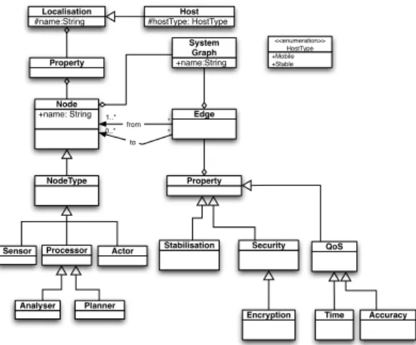
Figure 2: Feedback Control Loop Metamodel One way to provide visibility for FCL in an
application, is to find a way of specifying re-quired control features. To meet this goal, we present here a meta-model to express con-trol properties in the application. The pre-sented metamodel allows to express control elements concepts like sensors, processors,
or actors which correspond to architectural
el-ements aiming to sense, process, or act on the system respectively. The metamodel charac-terizes also the process flow between the ele-ments of the system, by offering concepts to express non-functional properties such as sta-bilization or security. All these concepts can
be used at design time by the application architect in order to specify control elements of the sys-tem, using annotation artefacts. The following section shows an example of how this metamodel can be used, by presenting a variant of the data processing model for the scenario presented above.
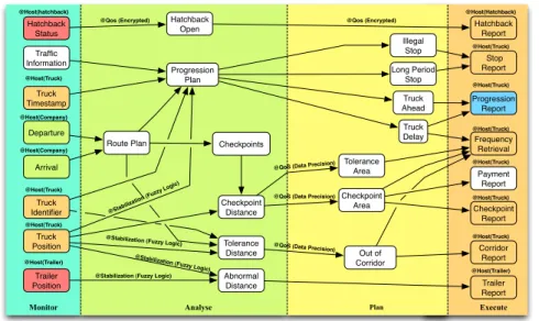
3.2 Data-oriented Modelling of Feedback Control Loops
Our model is inspired by the context policy specification of the COSMOS context processing framework [RCS08]. Concretely, the data processing model that we defined is a connected graph where the nodes reflect processed data, and the edges identify data dependencies. Nodes on the left side of Figure 3 are raw data sensors, while the right-side nodes describe decision actuators. Nodes located in the middle are called processor (analyzer, planner) nodes. The data therefore flows through the nodes, where it is incrementally transformed into information of an higher level of abstraction.
Figure3shows the specification of the real-time truck tracking infrastructure, that we intro-duced in Section 2. The shaded nodes of the graph identify data sensors and effectors of the infrastructure, whose location is statically assigned. For example, the Truck Position node is shaded to specify that the associated sensor is necessarily deployed in the truck. White nodes represent data processors, whose host is not explicitly identified and can therefore be deployed in any part of the infrastructure.
Truck Position Tolerance Distance Progression Plan Out of Corridor Frequency Retrieval Illegal Stop Long Period Stop Corridor Report Route Plan Traffic Information Hatchback Status Hatchback
Open Hatchback Report
Stop Report Arrival Truck Timestamp Truck Identifier Trailer Position Abnormal Distance Trailer Report Progression Report Truck Delay Truck Ahead Checkpoints Checkpoint Distance Tolerance Area Checkpoint Area Payment Report Departure Checkpoint Report
Monitor Analyse Plan Execute
@Qos (Encrypted)
@QoS (Data Precision) @QoS (Data Precision)
@Stabilization (Fuzzy Logic) @Stabilization (Fuzzy Logic) @Host(hatchback) @Host(Trailer) @Host(Truck) @Host(Company) @Host(Company) @Host(Truck) @Host(Truck) @Host(Hatchback) @Host(Truck) @Host(Truck) @Host(Truck) @Host(Truck) @Host(Truck) @Host(Truck) @Host(Trailer) @Qos (Encrypted)
@QoS (Data Precision)
@Stabilization (Fuzzy Logic)
@Stabilization (Fuzzy Logic)
Figure 3: Data Processing Model of the Feedback Control Loop.
Trailer Truck Geo Hub Customer Company Internet
Figure 4: Physical Infrastructure Deployment Model.
Then, the deployment infrastructure shown in Figure 4, specifies how the infrastructure is deployed as a network of physical or vir-tual devices, which can evenvir-tually host the data processors. The connections between the devices describe the available communication links.
3.3 Deployment and Execution of Feedback Control Loops
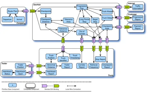
This section describes the runtime part of our approach, which exploits the data-oriented specifi-cation of the FCL, to generate a component-based infrastructure that implements it. In particular, during the feedback loop generation process, we convert the previously introduced models into software components, by combining the data processing and the deployment infrastructure mod-els. We can assign the unshaded data processors to the devices of the infrastructure. For each unallocated data processor, the algorithm computes the list of devices which are 0 or 1-hop away from the data dependencies. Then, the most relevant device selected for hosting the data proces-sor is the one that minimizes the memory consumption and the communication cost. Figure5
depicts a candidate architecture obtained when applying this algorithm.
The resulting architecture is mapped to the Service Component Architecture (SCA) [SCA] standard by applying the following rules: i) the nodes of the connected graph are mapped into
primitive components, ii) local data dependencies are converted into component wires, while
remote data dependencies are exposed through bindings, and finally iii) nodes that are located on the same device are grouped within composite components.
ECEASST Customer GeoHub Truck Internet Trailer Company push push push push push push push push push push push push push push push push pull pull push push push push A
Primitive Data Component Composite Component Remote SCA Binding Local Wire Connection
Hatchback Status Hatchback Open Trailer Position Route Plan Arrival Departure Truck Position Tolerance Distance Progression Plan Out of Corridor Retrieval Frequency Illegal Stop Long Period Stop Corridor Report Traffic Information Hatchback Report Stop Report Truck Timestamp Truck Identifier Abnormal Distance Trailer Report Progression Report Truck Delay Truck Ahead Checkpoints Checkpoint Distance Tolerance Area Checkpoint Area Payment Report Checkpoint Report
Figure 5: Component-based Architecture of the Feedback Control Loop.
4
Related Work
The RAINBOW[GCH+
04], ENTROPY[HLM+
09], and CAPPUCINO[RRS+
09] frameworks pro-vide components that fulfill the MAPE Loop (cf. section2.1) phases to support self-adaptation. Nonetheless, these frameworks propose a static or closed infrastructure for managing the adap-tation policies. Besides that, in terms of autonomic software system, literature abounds of many resources, such as KX (Kinesthetics eXtreme) [KPGV03], Astrolabe [BRV03], or Unity [CSWW04]. However, as in the case of autonomic frameworks, the lack of transparency in the design and the management of the FCL systems is one of the major limitations to the scalability of such systems. To solve the problem of the opacity and the non-scalability of existing FCL, some recent research works suggest that, “the feedback loops that control self adaptation must
become first-class entities.” [BSC+09]. The approach we propose in this paper stands in that
perspective. The idea is to generalize the autonomic MAPE model and to extend the CAPPU-CINO framework to address very-large-scale environments. In particular, we propose to reify the MAPE model as a very-large-scale data processing infrastructure, which converts data col-lected in the environment into real-time reactions. The data processing distribution is driven by the specification of data dependencies [RCS08] in order to maximize the performances of the system and balance the processing load among the nodes available in the environment.
5
Conclusion
We have outlined in this paper an approach for the engineering of FCLs drawing on the data flow model. We argue that, the data flow model comes with additional information that can be crucial for FCL engineering earlier at design time, to understand ongoing control mechanisms,
and later at runtime for an efficient adaptation of the system. We used the truck tracking scenario, to explain how to specify a data-oriented model of a FCL, and how to generate the underlying execution platform with the SCA standard. As futur works, we are planning to evaluate the overhead introduced by our approach in a realistic deployment.
Acknowledgements: The work reported in this paper is partly funded by the ANR ARPEGE SALTY project (http://salty.unice.fr) under contract ANR-09-SEGI-012 and FEDER project.
Bibliography
[BBD+
02] B. Babcock, S. Babu, M. Datar, R. Motwani, J. Widom. Models and issues in data stream
systems. In In Proceedings of the twenty-first ACM SIGMOD-SIGACT-SIGART symposium
on Principles of database systems (PODS’02). Pp. 1–16. ACM, New York, NY, USA, 2002.
[BRV03] K. P. Birman, R. V. Renesse, W. Vogels. Navigating in the storm:using astrolabe for
dis-tributed self-configuration, monitoring and adaptation. In Proceedings of the autonomic
computing workshop, 5th international workshop on active middleware services (AMS’03).
Pp. 4–13. 2003.
[BSC+
09] Y. Brun, G. D. M. Serugendo, H. G. Cristina Gacek, H. Kienle, H. M. Marin Litoiu,
M. Pezz`e, M. Shaw. Software Engineering for Self-Adaptive Systems (SEfSAS). LNCS 5525, chapter Engineering Self-Adaptive Systems through Feedback Loops, pp. 48–70. Springer, 2009.
[CSWW04] D. M. Chess, A. Segal, I. Whalley, S. R. White. Unity: experiences with a prototype au-tonomic computing system. In Proceedings of IEEE first international conference on
auto-nomic computing. Pp. 140–147. May 2004.
[GCH+04] D. Garlan, S.-W. Cheng, A.-C. Huang, B. Schmerl, P. Steenkist. Rainbow:
Architecture-Based Self-Adaptation with Reusable Infrastructure. IEEE Computer 37(10):46–54, Oct. 2004.
[HLM+
09] F. Hermenier, X. Lorca, J.-M. Menaud, G. Muller, J. Lawall. Entropy: a Consolidation Man-ager for Clusters. In Proceedings of the ACM SIGPLAN/SIGOPS international conference
on Virtual execution environments (VEE’09). Pp. 41–50. ACM, New York, NY, USA, 2009.
[IBM06] IBM. An Architectural Blueprint for Autonomic Computing. White paper, June 2006.
[KPGV03] G. Kaiser, J. Parekh, P. Gross, G. Valetto. Kinesthetics eXtreme: an external
infrastruc-ture for monitoring distributed legacy systems. In Proceedings of the autonomic computing
workshop, fifth international workshop on active middleware services (AMS’03). Pp. 22–30.
ACM, June 2003.
[RCS08] R. Rouvoy, D. Conan, L. Seinturier. Software Architecture Patterns for a Context Processing
Middleware Framework. IEEE Distributed Systems Online (DSO) 9(6):12, June 2008.
[RRS+
09] D. Romero, R. Rouvoy, L. Seinturier, S. Chabridon, D. Conan, N. Pessemier. Enabling
Context-Aware Web Services: Methods, Architectures, and Technologies. Chapter Enabling
Context-Aware Web Services: A Middleware Approach for Ubiquitous Environments, pp. 113–135. Chapman and Hall/CRC, July 2009.