HAL Id: hal-00432238
https://hal.archives-ouvertes.fr/hal-00432238
Submitted on 15 Nov 2009HAL is a multi-disciplinary open access archive for the deposit and dissemination of sci-entific research documents, whether they are pub-lished or not. The documents may come from teaching and research institutions in France or abroad, or from public or private research centers.
L’archive ouverte pluridisciplinaire HAL, est destinée au dépôt et à la diffusion de documents scientifiques de niveau recherche, publiés ou non, émanant des établissements d’enseignement et de recherche français ou étrangers, des laboratoires publics ou privés.
Pyramidal multi-band antennas for
GPS/Galileo/MicroSat application
Sami Hebib, Hervé Aubert, Olivier Pascal, Nelson Fonseca, Lionel Ries,
Jean-Marc Lopez
To cite this version:
Sami Hebib, Hervé Aubert, Olivier Pascal, Nelson Fonseca, Lionel Ries, et al.. Pyramidal multi-band antennas for GPS/Galileo/MicroSat application. Antennas and Propagation International Sympo-sium, 2007 IEEE, Jun 2007, Honolulu, United States. pp. 2041 - 2044, �10.1109/APS.2007.4395925�. �hal-00432238�
Pyramidal multi-band antennas for GPS/Galileo/MicroSat application S. Hebib* (1, 2), H. Aubert (2, 3), O. Pascal (1), N. Fonseca (4), L. Ries (4) and
J. M. Lopez (4)
(1) AD2M-UPS, 118 Route de Narbonne, 31062 Toulouse, FRANCE (2) LAAS-CNRS, 7 Avenue du Colonel Roche, 31077 Toulouse, FRANCE (3) INPT-ENSEEIHT, 2 Rue Charles Camichel, 31071 Toulouse, FRANCE
(4) CNES, 18 Avenue Edouard Belin, 31401 Toulouse, FRANCE Introduction
There is a constant increase of interest for multi-band antennas, mainly driven by the objective to reduce the number of onboard and ground antennas by integrating several applications on a single radiating element. In the framework of the Galileo satellite navigation system, the French Space Agency (CNES) proposed to study the possibility of combining GPS, Galileo and MicroSat telemetry (TM) applications on the same multi-band antenna. The GPS / Galileo bands used here include for example ARNS as well as high precision applications. This communication introduces a novel topology of trap-loaded multi-band antenna based on pyramidal structures [1]. The experimental results confirm the good performances observed during the electromagnetic simulations. The multi-band behavior and the required circular polarization characteristic of the proposed pyramidal antenna are validated experimentally.
Antenna design
Two interesting configurations can be considered to obtain circularly polarized antennas from linearly polarized ones. The first configuration uses quadratic phase excitations placed at the center of the structure [2] while for the second configuration, the quadratic phase excitations are located at the border of the antenna [3]. According to electromagnetic simulations, the latter configuration provides higher directivity with wider bandwidth as compared to the first one. Furthermore, the four feeding ports in this second configuration are all disjointed, making it easier to feed. However, this configuration suffers from a spurious interference effect which is an array effect induced by the non homothetic antenna shape. In addition to this, for our application, it presents insufficient radial directivity at high frequencies.
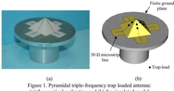
A solution to overcome these two drawbacks involves the use of the axis perpendicular to the antenna surface. The resulting pyramidal antenna (figure 1) provides a good radial radiation, hence possible improvement in the radial directivity. Furthermore, with this configuration, the feeding ports are brought closer to each other, leading to a reduction or even suppression of the
cumbersome array effect. A pyramidal inclining angle of 45 degrees presents a good trade-off between the expected radial and axial radiation performances. The multi-band behavior of this antenna is obtained using trap-loads. These loads can be lumped [3] or distributed [4, 5] elements. In order to simplify the process of antenna design and to reduce the computation time, the trap-loads used in the electromagnetic simulations are considered as ideal ON/OFF switches. The design and the simulation of the proposed antenna are performed using IE3D software based on the Method of Moments.
Antenna manufacturing
According to IE3D simulations results, the best impedance matching is obtained when the four feeding ports are located at the vicinity of the circular central hole of the ground plane. However, in practice, it is not convenient to place the SMA connectors at the edge of this hole. A solution is to locate the SMA connectors at a more convenient position and to use 50 Ω microstrip lines to connect them to the radiating elements, as shown on figure 1. The outer radius of the circular ground plane is chosen in order to reduce the edge radiation produced by the surface current on the ground plane. The four radiating elements that constitutes the antenna are printed with copper (width = 1 mm) on a relatively low-permittivity substrate (relative low-permittivity = 2.08 and thickness = 762 µm). The same substrate is used for the realization of the 50Ω-microstrip lines.
(a) (b)
Antenna measurements
The input return losses and the bandwidth performances of the antenna with ideal trap-loads are presented in Table 1. Measurements of input reflection coefficients were performed using the vector network analyzer WILTRON 37269A. It can be seen that the impedance matching in all bands is quite good, particularly for the second and the third bands (around ---18dB). A weaker impedance matching is obtained in the first frequency band (---13.11dB): post-simulations using CST
Figure 1. Pyramidal triple-frequency trap loaded antenna: (a) the practical realization and (b) the simulated model
50 Ω microstrip line Trap-load Finite ground plane
-180 -120 -60 0 60 120 180 -50 -40 -30 -20 -10 0 10
Elevation Angle (deg)
D ir ec tiv ity ( dB i) -180 -120 -60 0 60 120 180 -50 -40 -30 -20 -10 0 10
Elevation Angle (deg)
D ir ec tivit y ( dB i) -180 -120 -60 0 60 120 180 -50 -40 -30 -20 -10 0 10
Elevation Angle (deg)
D ir ec tiv ity ( dB i)
Microwave studio software have shown that this low impedance matching is caused by the metallic cylinder placed beneath the ground plane to reduce rear radiations (this post-simulations have confirmed that this cylinder has a little impact on the return losses of the two other frequency bands). Optimization of the full antenna using CST Microwave studio software is under way.
First band (GPS/Galileo) Second band (GPS/Galileo) Third band (MicroSat) Minimum return loss -13.11 dB -17.48 dB -18.91 dB Minimum RL Frequency 1.215 GHz 1.580 GHz 2.260 GHz
110 MHz 206 MHz 454 MHz Bandwidth
(|S11|<-10 dB) 9 % 13 % 20 %
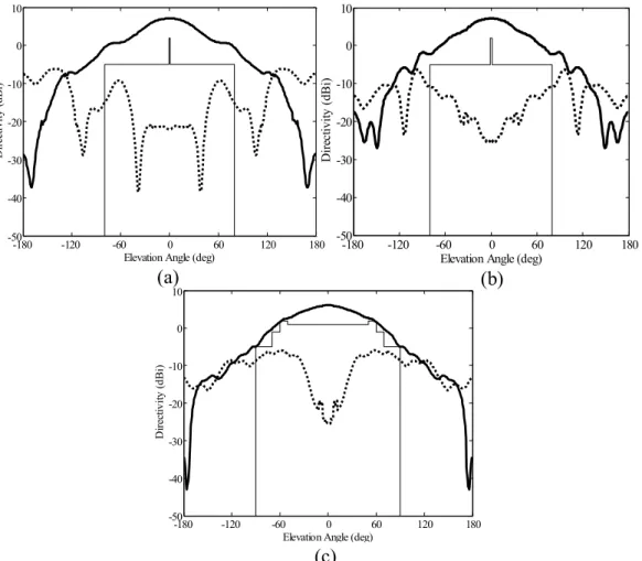
Radiation measurements were performed using the Compact Antenna Test Range (CATR) at CNES. Fig. 2 displays the measured RHCP and LHCP directivity patterns of the antenna at the three desired operating frequencies.
Table 1. The measured return losses and bandwidths for the multi-band antenna
Figure 2. The measured radiation patterns (RHCP : — ; LHCP : ··· ; Minimum required RHCP :
―
) for the multi-band antenna at:(a) 1.197 GHz, (b) 1.575 GHz and (c) 2.245 GHz
(a) (b)
The radiation specifications are satisfied in the GPS/Galileo frequency bands (centered at 1.197 GHz and 1.575 GHz) and slightly out of the technical requirements in some radiating direction for TM frequency band (centered at 2.245 GHz). Some minor adjustments can be proposed to improve radiation performances in this frequency band: for instance adjusting the inclination of the four radiation monopoles. From these experimental results we conclude that the multi-band behavior and the circular polarization of this antenna with ideal trap-loads have been validated experimentally.
Conclusion
A novel solution based on pyramidal structures with traps was designed and tested experimentally. The measurements results confirm the good performances obtained from the electromagnetic simulations. The solution suggested in this communication has been developed for a tri-band application but, it could also be advantageously applied for applications in multiple frequency bands. Moreover the exploitation of available volume offers new degrees of freedom for the design of the antennas such as the angle of inclination of the pyramid and the radius of the circular hole bored in the ground plan as well as the length of the cylinder beneath. The proposed multi-band antenna is easy to design and is flexible. It is a good candidate for other multi-band applications.
Acknowledgement
The authors would like to thank José DaBenta and Olivier Pigaglio for their contributions to the manufacturing of the antennas and Lise Feat, Mael Ferret and Daniel Belot for their contributions to the measurements of the various prototypes.
References:
[1] S. Hebib, H. Aubert, O. Pascal, “Multi-band antennas for GPS/Galileo applications,” Final Report, CNES contract: 60168/00, CNES, Dec. 2006, 47 pages.
[2] M. Ben Abdillah, O. Pascal, H. Aubert, “Cross shaped fractal antenna: a compact circularly polarized radiating element,” Microw. Opt. Technol. Lett., vol. 43, no. 6, pp. 518-521, Dec. 2004.
[3] B. Rama Rao, M. A. Smolinski, Cuong C. Quach, E. N. Rosario, “Triple-band GPS trap-loaded inverted L antenna array,” Microw. Opt. Technol. Lett., vol. 38, no. 1, pp. 35-37, July 2003.
[4] M. Ben Abdillah, O. Pascal and H. Aubert, “Distributed constant antennas for compact dual-band applications,” IEEE Antennas and Propagation Society Int. Symp., vol. 1B, Jul. 3-8, 2005, pp. 475–478.
[5] J. P. Gianvittorio and Y. Rahmat-Samii, “Fractal Yagi antennas: design, simulation, and fabrication,” Microw. Opt. Technol. Lett., vol. 41, no. 5, pp. 375-380, Jun. 2004.