HAL Id: hal-01745103
https://hal.archives-ouvertes.fr/hal-01745103
Submitted on 27 Mar 2018
HAL is a multi-disciplinary open access
archive for the deposit and dissemination of
sci-entific research documents, whether they are
pub-lished or not. The documents may come from
teaching and research institutions in France or
abroad, or from public or private research centers.
L’archive ouverte pluridisciplinaire HAL, est
destinée au dépôt et à la diffusion de documents
scientifiques de niveau recherche, publiés ou non,
émanant des établissements d’enseignement et de
recherche français ou étrangers, des laboratoires
publics ou privés.
Three-Dimensional Failure Patterns Around an Inflating
Magmatic Chamber
Muriel Gerbault, Riad Hassani, Camila Novoa Lizama, Alban Souche
To cite this version:
Muriel Gerbault, Riad Hassani, Camila Novoa Lizama, Alban Souche. Three-Dimensional Failure
Patterns Around an Inflating Magmatic Chamber. Geochemistry, Geophysics, Geosystems, AGU and
the Geochemical Society, In press, �10.1002/2017GC007174�. �hal-01745103�
Three dimensional failure patterns around an inflating
magmatic chamber
Muriel Gerbault1 , Riad Hassani2, Camila Novoa Lizama1, Alban Souche3
1GET IRD UR154, OMP 14 Av. E. Belin, 31400 Toulouse, France 2Geoazur, 250 rue A. Einstein, Sophia-Antipolis, France 3PGP, Department of Geosciences, University of Oslo, Norway
Key Points:
• The overpressure required for failure at the walls of a magma chamber depends on
its geometry and on the effective bedrock strength.
• Plastic shear bands (faults) initiate either from near the apex or the tip depending
on the symmetry and elongation of an oblate chamber.
• Elastic dilation at oblate chambers tip open concurrent magma pathways whereas
contraction around prolate chambers favors apex failure.
Corresponding author: Gerbault, [email protected]
Research Article Geochemistry, Geophysics, Geosystems
DOI 10.1002/2017GC007174
This article has been accepted for publication and undergone full peer review but has not been through the copyediting, typesetting, pagination and proofreading process which may lead to differences between this version and the Version of Record. Please cite this article as doi: 10.1002/2017GC007174
Abstract
Bedrock failure around an inflating magma chamber is an important factor that controls the occurrence of volcanic eruptions. Here, we employ 3D numerical models of elasto-plastic shear failure around an inflating crustal reservoir, to study how the induced fail-ure patterns depend on the geometry of the chamber, on the host rock strength and on the gravitational field. Our simulations show that either localized of diffuse plastic fail-ure domains develop in 3 stages. Failfail-ure initiates (stage 1) after a critical overpressfail-ure is reached, the value of which depends on effective host rock strength. Next, and with in-creasing applied overpressure, either distributed (for zero friction angle) or localized plas-tic failure zones (for 30◦ friction angle) form (stage 2), until they finally connect to the surface (stage 3). Cylindrical chambers develop prismatic shear zones that simultaneously merge from the surface and chamber walls. For spherical and prolate chambers, diffuse conical zones of failure develop from the chamber’s crest, whereas for oblate symmetri-cal chambers, shear bands initiate at the horizontal tips but bend back above the center of the chamber to reach the surface. In contrast for asymmetrical oblate chambers, shear bands initiate in their cylindrical section and vanish along the elongated direction. Here, magmatic fluids may migrate both through diffuse elastic dilation zones at the tips, and through localized shear zones from the crest. Our results thus suggest that natural obser-vations may be used to constrain the mode of failure occurring underneath a volcano. We discuss several natural examples in this context.
1 Introduction
The conditions for which a magmatic chamber can produce a volcanic eruption, and more specifically how magma breaks its way through crustal rocks, remain incompletely understood. This process depends on a number of coupled physical processes at multiple scales in space and time (Karlstrom et al. [2010], Degruyter and Huber [2014], Bonali
et al.[2015]). Inside the reservoir, the transfer of magmatic material and heat from deep sources, buoyancy, vapor exsolution and crystallisation all contribute to its internal pres-surization. Modelling studies that explore these processes use petrological, structural and chemical data. Outside the reservoir, the response of the surrounding bedrock to varia-tions in internal pressure controls the ability of the reservoir to expand, either as an ex-panding mush or in a more localised mode along dikes and shear zones that serve as mag-matic pathways towards the surface [Anderson, 1936; Petford et al., 2000]. Both mode I
and mode II magma conduits are observed in the field in a variety of contexts Woodcock
and Underhill[1987]; White et al. [2011]; Plateaux et al. [2012]; Spacapan et al [2017]. Several laboratory experiments show that dykes can propagate from self-induced shear failures rather than tensional hydraulic fracturing in the host rock Mathieu et al. [2008];
Abdelmalak et al. [2012]; Haug et al. [2017]. Another type of mechanical approach uses measurements of surface deformation in order to retrieve the geometry and location of magmatic sources at depth, formulating the problem in terms of an inflating or deflating magmatic cavity embedded in an elastic medium [Anderson, 1936; Mogi , 1958;
Mc-Tigue, 1987; Gudmundsson , 1988; Masterlark, 2007; Karaoglu et al. , 2016; Le Mevel
et al. , 2016]. Our approach here is based on this latter view-point, according to which the terms ’reservoir’ or magma ’chamber’ describe a magmatic fluid source of sufficiently low viscosity so that no significant tangential stresses are applied against its walls. Here, magmatic overpressure is conceptualised as an increasing uniform pressure inside a reser-voir of predefined geometry. This overpressure is assumed to increase faster than ther-mal heat transfer and viscous relaxation, and the reader is refered to other studies that ex-plore such thermal aspects [Gelman et al., 2013; Jellinek and de Paolo , 2003; Burov et al., 2003; Karlstrom et al. , 2010]. The influence of a volcanic edifice, bedrock mechanical heterogeneities and tectonics stresses [Pinel and Jaupart, 2005; Menand, 2011; Currenti
and Williams, 2014; Karaoglu et al. , 2016] are also neglected here but will be briefly dis-cussed later on.
The present study aims at assessing 1) the pressure threshold for and 2) the pattern of elasto-plastic deformation in a three-dimensional (3D) bedrock space, extending the two-dimensional (2D) study of Gerbault [2012a]. Here the term ’plasticity’ is used in the sense of time-independent plasticity (no viscous effects) to describe brittle failure alone.
The community appears divided on whether it is appropriate or not to account for the gravity body force in numerical models of volcanic inflation (Grosfils et al. [2015]). Obviously, gravity plays a first order role on bedrock failure conditions [Gerbault, 2012a], on the geometry of magma propagation with respect to an edifice load [Corbi et al., 2015], and on buoyancy contrasts driving magma upward [Lister and Kerr , 1991; Watanabe et al. , 2002]. However, many models neglect the gravitational loading of the bedrock itself, assuming that volcanic deformation and eruptions result from a change with respect to a stage previously at equilibrium and without deformation; therefore the influence of the isotropic component of the stress field is supposed to cancel out. Actually neglecting
grav-itational loading is implicitely equivalent to the assumption that the crust has lithostatic fluid pore-pressure everywhere. The validity and implications of this assumption have been recently thoroughly discussed in Grosfils et al. [2015], and it is not the aim of the present study to debate this. Nevertheless, in the aim of bridging the gap between com-munities we shall present here models with and without gravity, and with and without friction. A situation in which gravity is neglected thus aproximates a bedrock with litho-static pore-fluid pressure everywhere, whereas a case with gravity and zero friction angle approximates a dry crust that has been thoroughly weakened by multiple fractures and mo-bilization [Ikari et al., 2009], End-member models without friction and without gravity constitute extreme cases where the bedrock fails at a minimum applied internal pressure. On the other hand, cases with friction and gravity correspond to standard dry resistant bedrock, that fails at maximal internal pressure conditions.
The questions adressed here are: 1) can 3D failure patterns be directly deduced from 2D predictions? and 2) what can such predictions of 3D deformation patterns and pressure conditions teach us about the underlying magma reservoir geometry? In the following, we first recall previous predictions of the critical overpressure leading to bedrock failure around cylindrical (2D) and spherical (3D) magma chambers. Next we present our nu-merical method and reproduce in 3D previously published 2D results. We display a com-parison of the overpressure necessary for the onset of shear failure at the chambers walls for various oblate to prolate geometries, using the study of Currenti and Williams [2014] and an alternative code (A. Souche, pers.comm.). Section 3 details the evolution of the stress and strain fields with increasing overpressure, for spherical, oblate and prolate reser-voirs. Cases without friction and without gravity are also discussed. We finally comment on the influence of these chambers geometries on surface deformation, on the conditions for mode I versus mode II failure, and on how magmatic pathways may be influenced by such patterns of stress and deformation. We briefly review other parameters that may play a role as well and draw some implications for natural volcanic systems.
2 Previous predictions of failure initiation, mechanical model and numerical method
2.1 Analytical predictions for bedrock failure
The stress and strain fields resulting from an inflating spherical source have been studied for nearly a century, since pioneer works in an elastic half space (Jeffery [1921];
Anderson[1936]; Jeffery [1921]; Mogi [1958]). It is (still) commonly assumed that ten-sile failure (mode I) initiates along the walls of a magmatic chamber submitted to an in-ternal overpressure (radial ∆P), in locations where the tangential stress is minimal (or hoop stress σθθ, defined as the normal stress perpendicular to the radial direction acting in the tangential plane, Jeffery [1921]; McTigue [1987]). Here, overpressure ∆P is the pressure in excess of the lithostatic pressure Pl = ρ g z (at depth z, negative downward).
For a spherical chamber, the critical overpressure is expressed as a function of the cham-bers depth H and radius R, and the bedrock’s tensile strength To (e.g. Pinel and Jaupart
[2005]):
∆PT =
H2− R2
H2 · To. (1)
Grosfils [2007] demonstrated the necessity of accounting for gravity when assess-ing the conditions for tensile failure, since indeed the force balance involves a gravity-dependent hoop stress that does not cancel out. Consequently when accounting for a grav-itationally loaded half space, much larger critical overpressure is required for the onset of failure at the chamber walls. Grosfils [2007] predicted that this critical overpressure depends on depth z and on the free surface shape factor C1 = 1 + 2 tan2α (α the angle
measured from the origin at the surface and between the vertical axis and a point along the chamber, Jeffery [1921]) :
∆PT G =
2 C1
· (To−ρgz). (2)
For ellipsoidal magma chambers embedded in a gravity field, Grosfils [2007] predicted that vertical dikes tend to form at the apex of spherical and prolate chambers at depths greater than 2 km, whereas lateral sills form instead around oblate chambers deeper than 1 km.
With gravity and in 2D, Gerbault [2012a] investigated the conditions for either ten-sile (mode I, hydrofracture) or shear failure (mode II, Coulomb type), by modeling the evolution of deformation and failure around a progressively increasing internal pressure.
Gerbault et al.[2012] fitted tensile failure predictions by Grosfils [2007], however shear failure was actually found to be triggered prior to tensile failure at the chamber walls, unless the bedrock has a lithostatic pore fluid pressure. In that case, the liquid pressure inside the pores of the bedrock exerts a resisting buoyancy force to the ambient normal component of the stress tensor [Hubbert and Rubey, 1959], which thus cancels its influ-ence on the yield threshold. Even a medium at an intermediate state of hydrostatic pore
fluid pressure was found to still fail under mode II prior to mode I at the walls of the chamber. Gerbault [2012a] evaluated (in 2D), the critical overpressure ∆PMCS necessary
to reach the Coulomb yield envelope at any point at depth z along the chamber wall, as a function of bedrock friction φo, cohesion Co or tensile strength To (Co = To· tan φo), and
the free surface factor C1 :
∆PMCS= 2
sin φo
1+ sin φo+ C1· (1 − sin φo)
· (To−ρgz). (3)
When failure occurs at the apex, α= 0, C1 = 1 and ∆PMCS= (To−ρgz) · sin φo.
In an elastic 3D medium, the stress balance at a spherical cavity wall requires that the tangential stress is half the exerted outward normal pressure (J2 = ∆P/2, [Timo-shenko and Goodier, 1970], as opposed to a cylindrical cavity where they become equal (J2 = ∆P). Consequently, Gerbault [2012a] predicted that for a sphere, the critical
over-pressure for the initiation of shear failure would be approximately multiplied by 2 com-pared to plane-strain conditions. Currenti and Williams [2014] obtained slightly lower val-ues. For comparison, the state of stress produced by a spherical inflation in an infinite 3D elastic medium is available from e.g. Timoshenko and Goodier [1970]: the surrounding external pressure is null along the chamber walls, cancelled out by the hoop and shear stresses. If the medium is elasto-plastic with a Tresca yield stress k, a spherical plastic zone of radius c develops and increases with increasing internal pressure ∆P. The result-ing overpressure Pp inside the plastic domain (r < c) relates to the applied ∆P as:
Pp(r< c) = 2 · k · (ln r R+ 1 3) − ∆P= 2 · k · (ln r c). (4)
We deduce a crude estimate of the state of pressure necessary to generate shear failure (mode II) at the chamber wall (∆P = 2k/3) up to the surface (∆P = 2k(ln H/R + 1/3)). Note that a Tresca yield criterion corresponds to a Coulomb failure criterion with friction φo = 0 and cohesion Co = k/2. We will compare and discuss our numerical results with
these values in section 3 below.
2.2 Mechanical model, numerical setup and method
The mechanical model, its governing equations and the elasto-plastic constitutive law are provided in Supplementary material. Below we describe the initial geometry of the model domain and our choice of boundary conditions. Our numerical method, Adeli, is also presented.
Initial geometry and boundary conditions
Because of obvious symmetry, the model’s initial geometry covers only a quarter of domain Ω. It is defined as a cubic domain of side length L, containing an ellipsoidal cav-ity of principal axes parallel to the coordinates axes and centered at point (0, 0, −H) (Fig. 1). The vertical semi-axis (z direction) of this cavity is denoted by a, the two horizontal semi-axes (x and y directions, respectively) by b and c. Boundary conditions are:
• the top ground surface (initially at z= 0) is a stress-free surface: σ · n = 0,
• the vertical boundaries (at x= 0, x = L, y = 0 and y = L) and the bottom boundary
(z = −L) are free-slip and held stationnary in their normal direction: vtn = 0 and
σt= 0 (where σt = (I − n ⊗ n)σ · n is the tangential stress vector),
• the curved wall chamber boundary is submitted to a normal stress corresponding to
the sum of lithostatic pressure pl = ρg|z| (where g = kgk) and an overpressure ∆P:
σ · n = −(pl+ ∆P) n.
All models are initialised with isotropic lithostatic stress components everywhere (the weight of overburden rock ρ g z), a uniform density ρ= 2500 kg m−3, and gravity, set either to g= 0 or g = 10 m/s2. Thus models begin at ∆P= 0 at equilibrium, e.g. with no initial deformation. Throughout this study, tensile stresses are defined positive.
In the models, the abrupt application of a normal load on the chamber walls can locally exceed the brittle yield stress and thus lead to unrealistic distorsions. Therefore the internal overpressure ∆P is applied in incremental steps δp, large enough for the total computing time to remain reasonable, but small enough to achieve non-linear convergence during each pressure increment (as in Gerbault et al. [2012]). Consequently our model results below have an uncertainty in ∆P of about ' 10% corresponding to the step-wise pressure increment and to the sampling frequency of the output.
The mesh is defined with tetrahedral elements of length size 25 m in the first 10 km3 of the domain, departing at coordinate (0, 0, 0). Grid resolution progressively reduces in all directions to a maximum size of 10 km at the opposite corner of the mesh-domain located at coordinate (80, 80, −80) km. The total number of elements is on the order of 2 − 6 × 10⁶ depending on magma chambers geometries.
A reference spherical chamber model is set up with a center depth H = 7 km and radius R = 2 km. Relative to this case, the shape of oblate chambers is explored while
maintaining a constant vertical axis a= R and varying the horizontal axes b and c. Sym-metrical oblate chambers have two elongated horizontal axes (pancake shape), while asym-metrical oblate chambers have only one elongated axis c, along direction y (in the two other directions b = a = R = 2 km). Prolate chambers in turn are studied with constant horizontal axes (b= c = R), and a variable vertical a axis (cigar shape).
Numerical method
An approximate solution to the continuous problem (Eq. S1-1) is computed using the finite element code Adeli [Hassani et al., 1997]. Adeli has been used to simulate a va-riety of geodynamical contexts, including subduction zones [Hassani et al., 1997; Cerpa
et al., 2015] and the seismic cycle [He and Chéry, 2008; Contreras et al., 2016]. This code uses the dynamic relaxation method (Cundall and Board [1988], Cundall [1989]) to solve the set of non linear equations obtained after a finite element discretization of the quasi-static equilibrium equation. This time-explicit method uses an adaptative time-step and basically damps the out-of-balance forces; it was designed specifically to track the development of localised plastic strain. It has been widely tested in the engineering and academic Earth Sciences communities, as a product of the commercial Itasca Consulting
Group(FLAC code), and via academic codes such as Parovoz [Poliakov et al., 1993;
Ger-bault et al., 1998; Burov et al., 2003] (or Flammar later on) and Adeli. In Adeli, common time-integration algorithms like elastic prediction-plastic correction [Ortiz and Simo, 1986] are used to compute the current stress state. More details about numerical aspects can be found in Hassani and Chéry [1996]; Chéry et al. [2001]; Cerpa et al. [2015].
2.3 2D behavior
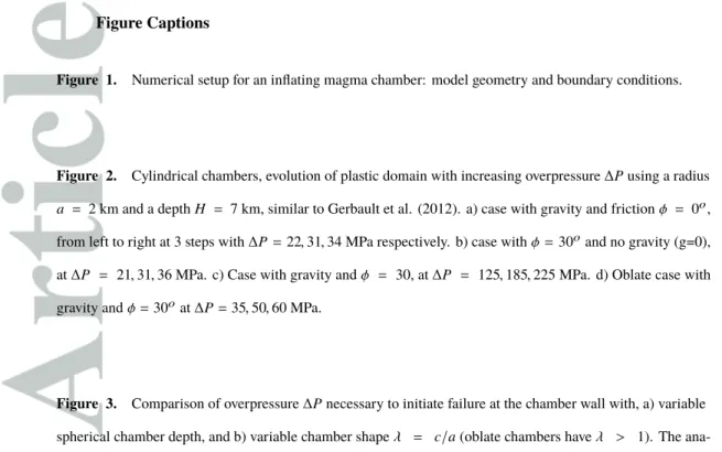
In plane-strain, with gravity and φ= 30o, three stages characterise the development of plastic deformation with increasing overpressure (Fig. 2c, Gerbault et al. [2012]), and with which we subsequently compare our 3D models :
• Stage 1, failure initiates at the surface above the center of the magmatic chamber, • Stage 2 shear failure initiates along the chamber wall (at overpressure satisfying
Eq.3. Shear zones develop oriented ∼ 60o apart, and depart at about a quarter arc distance from the chamber’s apex, consistent with predictions (Grosfils [2007];
geom-etry (a term that describes the slip lines obtained by Nadai [1931]; d’Escatha and
Mandel[1974]). Both the upper plastic domain at the surface, and the excentric plastic domain at the chamber walls, form two conical domains that progressively expand towards each-other.
• Stage 3 is defined with the connection of these two conical plastic domains. Shear
bands continue to expand outwards from the chamber, and an increasing number of shear zones develop, directly connecting the wall’s lateral edges to the surface. At this stage the mechanical connection between the chamber and surface is obvi-ous. This geometry is consistent with solutions obtained in tunneling mechanics (Gerbault et al. [2012], and references therein). This stage 3 is likely beyond the eruptive stage of a natural volcanic system, yet it constitutes an upper limit for its general failure.
Figures 2 illustrate four models of two-dimensional reservoirs in three dimensions (equivalent to plane-strain conditions), testing the influence of φ and gravity. For each of these cases the figures display three stages of evolution of the plastic domain (εp) :
• The first model case has a friction angle φ = 0 and gravity (equivalent to a von
Mises criterion Fig. 2.a). Plastic failure develops first at the wall at ∆P1 = 12 MPa,
consistent with Eq. 1, and then at the surface. Connection occurs after ∆P3 = 29.5
MPa (stage 3).
• The second case has friction φ = 30o and no gravity (g = 0), equivalent to a
Coulomb-type bedrock at a state of lithostatic state pore-fluid pressure (Figure 2.b). The evolutionary stages are identical, but excentric shear bands develop at depth and a plastic cone forms at the surface bounded by a sharp 30o to 45o dip-ping shear band. Critical overpressures are obtained of the same order (∆P1 = 12
MPa,∆P3= 32 MPa).
• The third case with friction φ= 30o and gravity accounted for, refers to the
stan-dard situation of dry bedrock. Failure initiates at the surface (stage 1), then at the apex of the chamber wall (stage 2), and these two plastic domains connect (stage 3), similarly to Gerbault et al. [2012]. Critical overpressures now exceed 100 MPa (Table 1).
• The last case displays an oblate-cylindrical chamber with b = 7 km, gravity and
then affects the chamber’s tip at 7 km depth, progressively forming a major inclined shear band that reaches the surface at c.a. x ' 10 km. Critical overpressures reach now ∆P1= 15 MPa and ∆P3= 60 MPa.
The above first two model cases without gravity reach the yield envelope along the cham-ber walls first, whereas the two last cases with gravity fail first at the surface, as expected. The three circular-cylindrical cases see their plastic domain connect the chamber and the surface along the y = 0 plane, forming the typical 2D conical domains on top of radial outward (excentric) domains. Localised structures only appear when φ = 30o, consistent with non-associated plasticity [Vermeer and de Borst, 1984; Gerbault et al., 1998; Nadai, 1931].
The plastic domain evolution around an oblate chamber is noteworthy: while the plastic shear domain initiates from the surface center progressively downward, the final connection of the plastic domain from the chamber to the surface occurs via the tip. This ’outwards-subvertical’ geometry of shear failure is consistent with previous predictions of tensile failure (e.g. Anderson [1936]; Gudmundsson [2006]) based on the coinciding loca-tion of the maximum intensity of the minimum principal stress σ3 and the orientation of
maximum principal stress σ1. We shall see that in 3D this situation becomes more
com-plex, and for sake of discussion clarity below, we will further refer to this conventional prediction as the "σ3/σ1 rule".
3 Three-dimensional geometries and the development of shear failure
Next we study the evolution of elasto-plastic behaviour in 3D. Below, we start with a comparative study that evaluates the critical overpressure necessary to reach wall shear failure as a function of the chamber’s geometrical characteristics. Then for each spherical, oblate and prolate cases we describe the evolution pattern of the stress and deformation fields, the plastic domain and the associated internal overpressure. A final series of tests presents a comparison of surface deformation according to different geometries.
3.1 Comparative study
A comparison of the critical overpressure for the onset of shear failure is performed against the study of Currenti and Williams [2014], in order to check the robustness of the results obtained with Adeli. In addition, we present numerical calculations obtained with
another implicit finite element method (developped by A. Souche, pers.comm., www.bitbucket.org) that allows for a finer spatial discretization of the chamber walls. For this purpose, the
model parameters are set accordingly to those used by Currenti and Williams [2014], which we refer to as the "CW models": Young’s modulus E = 75 GPa, density ρ = 2600 kg/m3,
φ = 35o, C = 5 MPa. We also report the results obtained with R = 2 km corresponding to
our main modeled case, with elasto-plastic properties described in the setup section. The critical overpressures obtained with Adeli and for different depths H, are re-ported in Table 1 and displayed Fig. 3a. Our results fall in between those of Currenti and
Williams[2014] and the approximation by Gerbault [2012a] (Eq.3 multiplied by 2, shift from 2D to 3D). The critical overpressure ∆P varies linearly with increasing chamber’s depth.
The results obtained by A. Souche in Fig.3a (labelled low res. and
Adhoc-high res.) were obtained with a mesh discretization at the wall boundary of 70 m and 8.6 m respectively, and indicate that a lower model resolution leads to an underestimation of the critical overpressure needed for failure. Numerical accuracy could be gained by using even finer mesh discretization, which we haven’t used given the computational cost of 3D calculations. Another comparison was performed with A. Souche’s code assuming either a fixed or a mobile wall boundary (meaning either prescribed zero motion or free motion). These two tests did not show noticable variations of the critical overpressure, allowing to conclude that for this mechanical configuration at least, the fixed wall boundary condition remains valid within the early plastic deformation stages (stages 1 to 2). All subsequent results developed with Adeli were obtained by considering a mobile wall boundary.
The comparison of critical overpressures as a function of the chamber’s shape ra-tio λ = b/a, is displayed for 2 different depths H = 0.5 and H = 2 km in Fig. 3b. The Adeli models slightly overestimate ∆P with respect to the other approaches for very elongated geometries, but it matches the trend that maximum overpressure is required for nearly spherical chambers (λ ' 1.2). This suggests that in nature spherical magma reser-voirs might not be the most appropriate geometry to trigger an eruption. However this is a commonly used geometry when interpreting measured surface deformation [Mogi , 1958;
3.2 Spherical chambers
The reference spherical model is displayed Fig. 4a, with gravity and friction φ= 0o.
Failure initiates simultaneously around the chamber walls, at ∆P ' 13.8 MPa (labelled ∆P1 in Table 1) and fits eq.4 with r = R = 2 km, and k = 20 MPa. This plastic domain
then expands radially and reaches the surface at ∆P = 58 MPa (stage 3, labelled ∆P3 in
Table 1). This modeled pressure can be considered to match the prediction of 63 MPa provided by Eq.4 for a plastic domain of radius r = H = 7 km, as it stands within the ' 10% uncertainty of the applied numerical step-wise pressure increment specified above. The slight difference between both solutions may be attributed to the presence of the free surface that impedes the medium to store stresses above the top surface, as opposed to an infinitely wide medium. Note also that until stage 3, the plastic domain is embedded in the elastic domain so that elastic solutions for surface displacements are still a valid approximation (as shown by Gerbault et al. [1998] and Gerbault [2012a]).
With bedrock friction φ = 30o and no gravity (Fig. 4b, assimilated here to a state of lithostatic pore pressure in the bedrock), the plastic domain around the inflating sphere expands radially as well, and at similar overpressures to the preceding case. However now, both plastic domains merge at about 2 km depth above the chamber’s central axis, as op-posed to the case with φ= 0 and no gravity, where the plastic domain connects at a dis-tance closer to the surface and at ca. 2 km away from the central vertical axis.
With bedrock friction φ = 30o and gravity (Fig. 4c), the inflating spherical
cham-ber fails first at its apex and then at the surface, in reversed order to a cylindrical chamcham-ber. An overpressure ∆P ' 120 MPa is required for failure to initiate at the chamber walls, whereas only 105 MPa were required in the cylindrical case. This difference is justified by the fact that overpressure ∆P against the internal walls of a sphere produces less vol-umetric increase (∆V ) than against an infinitely long cylinder, explaining the necessity of greater loading to reach the failure threshold at the surface.
During stage 2 when overpressure progressively increases in the spherical chamber , we note that maximum values of σ3 develop along the lower half domain of the chamber
walls and that the orientations of σ1 point radially outwards (Figs. 5), thus suggesting that
diking should develop from these deepest edges according to the "σ3/σ1 rule" mentionned
above. However, we also note that the upper half of the sphere develops contraction in a plastic regime (blue domain in mid panel Fig.5b,c), which logically impedes any tensile
opening there. Consequently this explains why the onset of failure actually occurs near the apex of the chamber.
In the spherical chamber, stage 3 describing the connection of the plastic domain from the chamber to the surface, occurs at an overpressure ∆P ' 420 MPa (Fig.5c), much greater than for a cylindrical chamber(∆P ' 160 MPa, Table 1, Fig.5a). Here, both plas-tic domains expanding from the chamber walls upward and from the surface downward slowly converge, revealing the kinematics related to this mechanical system: shear senses that border the upward moving deepest plastic cone immediately above the chamber (con-tracting domain), converge and push inward from below, while shear senses that border the shallowest plastic cone diverge upward (inward dipping fault planes, dilating domain).
3.3 Oblate geometries
Now the chamber is set elongated horizontally, and we distinguish symmetrical and asymmetrical oblate geometries. Symmetrical chambers have equal horizontal axes b= c. Asymmetrical chambers are only elongated along their c axis in the y direction, while their shape remains circular in the y= 0 plane with axis b = a = 2 km.
In all cases now, shear failure initiates closer to the elongated horizontal extremity of the chamber, confirming the prediction based on the standard σ3/σ1 rule without
grav-ity, and those accounting for gravity [Grosfils , 2007; Currenti and Williams, 2014]. This hints that internal magmatic fluids may tend to expel via these lateral edges of the cham-ber. The development of failure at these lateral tips is a logical consequence of prevailing tensile conditions induced by the application of a uniform load along sharply curved walls. Hence dilation occurs in the bedrock surrounding these tips (cf. red areas in mid panel Figs. 6b and 7b). We shall see below that the subsequent evolution pattern may however, become complicated.
For symmetrical geometries, two cases with b= c = 4, 7 km are displayed (Table 1, Figs. 6b-c), which can be understood as intermediate cases to the spherical and cylindrical oblate end-member cases (Figs. 5b and 6a). As the horizontal axis decreases from 7 to 4 km, the critical overpressure for wall failure increases (∆P1, Table 1), plasticity initiates at
the tip for a greater overpressure, and the plastic domain tends to bend back towards the centre above the chamber. The plastic domain at the surface expands radially, and no clear
shear bands manage to localise since they join at a central point at mid-depth (between 1 and 4 km depth).
For asymmetrical geometries, three cases with c = 4, 7 and 20 km (Table 1, Figs. 7) show another type of development of plasticity, also in between the spherical and the cylindrical end-members. First, plasticity develops for smaller overpressure values with increasing chamber’s elongation (increasing axis c). Second, shear bands form at depth along the y= 0 plane, more localised as the chambers’s elongation increases. Shear zones initiating close to the vertical axis produce inward dipping fault planes, and they straighten up as they expand towards the elongated axis (they become more rectilinear in the increas-ing y direction). It might be useful in specific studies, to track how upliftincreas-ing and subsid-ing areas dip and rotate along fault planes with depth, in order to identify the chamber’s geometry. Such inclined structures may appear challenging to track from field exposure and to attribute to a simple consistent tectonic stress field, in particular at the depth where compressional and tensile stress fields merge (blue to red transition in mid panels Figs.7).
A key result from the asymmetrical models is that, whereas shear failure initiates at the chamber’s tip (elongated axis c in the x = 0 plane), it remains confined there. Mean-while the plastic domain develops along the vertical plane y= 0 where the chamber’s wall is circular, connecting the chamber and the surface. In fact, while the tip of the chamber is under a dilating regime, σ3 is not maximum there, but is maximum instead around the
circular section in the vertical plane y = 0 (Fig. 7 right panels). Note also that, although shear failure occurs at the chamber wall in similar locations to those predicted for tensile failure, (at an inclined angle from the vertical, cf. Grosfils [2007]), it then follows a track oriented at 30o from σ1 (in contrast, a dike would be oriented parallel to σ1).
3.4 Prolate geometries
Now we discuss cases of prolate chambers with elongated vertical axis a and fixed horizontal axes b = c = 2 km (Figs. 8, Table 1). A main case has depth H = 9 km and axis a = 4 km, so that the apex remains at 5 km depth for comparison with previous geometries. Other cases test depths H = 7, 12, 23 km and axis a = 7, 20 km, with and without gravity (Table 1).
Whatever the elongation or whether gravity is accounted for or not, the onset of fail-ure always occur at the chamber’s apex, in consistency with other predictions [Grosfils ,
2007; Currenti and Williams, 2014]. Without gravity, both the apex and bottom tip fail si-multaneously (Fig. 8a). Then, during stage 2 an amphora-shaped plastic domain develops, with a cone of diffuse plastic strain at the surface (dilating domain, Fig. 8b), similar to the spherical case.
When considering the deformation and principal stress field (Fig. 8b,c), we note that the sub-vertical walls of these prolate chambers are under a compressional state of stress, in contrast to tension developing at the horizontal edges of oblate chambers. Such contrac-tion should impede the development of radiating dikes, despite an appropriate locacontrac-tion and magnitude of the principal stresses (σ3/σ1 rule, discussed further below).
When considering the plastic pattern produced with different prolate geometries, we note that the plastic domain connects (stage 3) at less overpressure for a less elongated chamber, for a shallower apex, and of course, when gravity is not accounted for (Figs. 8, Table 1). Around very elongated chambers, the connection of the plastic domain to the surface requires high overpressure, even without gravity (Table 1). Yet we note that σ3
along the wall is minimum right at the vertical tip (Fig. 8c) right), in apparent contradic-tion with the classical prediccontradic-tion of tensile failure there.
3.5 Conditions for localised deformation
Non-associated plasticity, which refers to material properties of differing friction and dilatancy angles, is a necessary condition for deformation to localise in a uniformly loaded, homogeneous medium [Nadai, 1931; Vermeer and de Borst, 1984]. In rocks, the friction angle approaches 30◦ while the dilatancy angle approaches 0◦. As a confirmation, in all our models thin localised shear bands only form when the friction angle is non-zero. More specifically, localised shear bands form at depth and relate the chamber walls to the surface in cases when the chamber is sufficiently oblate. The plastic domain remains dif-fuse instead when the chamber’s geometry is prolate.
During the intermediate stage 2 above prolate chambers, an annular ring of plas-tic shear failure develops at the surface at some distance from the chamber’s center (Fig. 9a). We find that this zone of plastic shear becomes perceptible at the surface as when ap-proaches the value H − b, but this remains to be confirmed by complementary tests cover-ing a full range of geometries. It results from a radial contraction exerted in the horizontal plane by the chamber’s overpressure, which propagates upward to the surface. If such an
annular plastic shear zone (perhaps ring or concentric fault zone) is observed by geode-tic measurements above natural magmageode-tic chambers, it may hint to a vergeode-tically elongated magma reservoir at depth (perhaps a plug intrusion,e.g. Dieterich and Decker [1975]).
Some of our models also show the development of localised excentric shear bands at the surface, however at overpressures significantly beyond stage 3. Such overpressures might be considered unrealistic under dry bedrock conditions, since they exceed by a fac-tor of about 5 the standard values derived from estimates for natural volcanic systems, which are generally estimated not to exceed ∼ 100 MPa [Masterlark, 2007; Jellinek and de
Paolo, 2003; Karlstrom et al. , 2010]. In our model of an inflating sphere with φ = 30o and zero gravity, overpressures of about 120 MPa generate excentric shear bands at the surface (Fig. 9c). These structures deserve to be studied in greater detail since they are re-ported in many places worldwide as well as on other planets (Ernst et al. [1995]; Minakov
et al. [2016]).
4 Discussion
Below, we further discuss three points that our modeling results raise specifically: the conditions for either mode I or mode II failure around oblate chambers (section 4.1), the dependency of surface deformation on 3D chamber geometry, with a discussion exam-ple from the Laguna del Maule, Chile (sections 4.2 and 4.3), and the potential influence of our modeled 3D stress and strain fields on magmatic pathways (section 4.4). We dis-cuss these points mentioning briefly specific areas, and we make more general comments on other aspects controling magma propagation from inflating volcanic reservoirs (section 4.5).
4.1 Tip or top failure around oblate chambers
Our numerical study above does not account for the occurrence of tensile failure. Since it had been shown that the shear failure envelope is reached prior to the tensile yield in cylindrical, and by extension to spherical geometries (and with gravity, Gerbault [2012a]), we assumed that to a first order, the same situation would occur in ellipsoidal geometries. Yet this remains to be demonstrated specifically at the tip of ellipsoidal cham-bers. Many approaches based on the theory of elasticity assume that tensile failure occurs in locations where the principal stress σ3 is maximum and in a direction parallel to σ1
(e.g. Anderson [1936]; Gudmundsson [2006]). When plotting these fields in our models we have seen that (i) shear failure does not always initiate in such domains, and (ii) that the location of maximum σ3 does not always occur at the tip of 3D oblate chambers (e.g.
Fig. 7), thus questioning whether mode I failure at the tip of magma chambers is the main mechanism by which magma migrates and potentially erupts at the surface.
The development of a plastic shear zone from the tip of an oblate chamber, either straight up outwards or instead curving back towards the center up to the surface, also likely depends on the depth/shape ratio H/R of the magma chamber. We may gain in-sight on this from an evaluation by Salençon [1969], based on plastic slip-lines theory: the slip-lines departing from a pressurizing indenter of half-width R can intersect prior to reaching the free-surface at a maximum distance H/R > 5.29. We thus guess that oblate magma chambers deep enough will rather produce intersecting slip-lines above their apex instead of failing at their lateral edges. We may extend this reasoning and propose that, conversely, there should be a critical width-to-depth ratio of a magma chamber, beyond which outwards sub-vertical shear zones will connect the lateral tips to the surface. Such a magic number would also depend on the third axis of the magma chamber, thus requiring another set of tests which we choose not to explore in this already lengthy contribution.
As an example, the Torres del Paine pluton, Chile, is a well preserved oblate crustal magma body that has been exposed by glacial erosion. Many dikes protrude from the chamber walls into the host rock, with in appearance a higher concentration at the tip than at the roof of the pluton [Skarmeta and Castelli, 1997; Leuthold et al. , 2012]. However, a large portion of the roof is actually missing. If this pluton can be assimilated to an in-flating oblate magma chamber, we may then propose to interpret the dikes at its tip as aborted structures, and that magmatic fluids in the reservoir either further migrated via failure pathways developping from the roof (however vertical magmatic flow is not ev-ident from field data), or that they stagnated within the reservoir, progressively cooling down without further expansion. This behaviour is consistent with the rather asymmetrical oblate shape of the Torres del Paine pluton (horizontal axes of about 7 and 17 km).
4.2 Surface deformation and 3D chamber geometry
Forty years ago, Dieterich and Decker [1975] numerically modeled the elastic defor-mation produced by inflating spherical and non spherical chambers, concluding that
differ-ent patterns of surface displacemdiffer-ents allow to iddiffer-entify differdiffer-ent source geometries. Today, this issue remains crucial as pointed by Remy et al. [2014], who showed that a sphere, a prolate ellipsoid or a planar crack located at different depths can all explain the surface displacements measured at Lazufre Volcano, Chile. In order to help decipher between pos-sible reservoir geometries, we present two series of comparisons below.
A first series of tests displays surface displacements for a given arbitrary overpres-sure ∆P= 150 MPa. Fig. 10a shows the resulting surface displacements and plastic strain for a sphere, a cylinder, an oblate and a prolate chamber at φ = 30o and with gravity. The spherical case produces a uniform circular bulge, of maximum amplitude ' 1 m, and about 7 times less than in 2D at this given internal overpressure. The associated plastic domain affects a relatively small area at the chambers’ apex, in contrast with the cylindri-cal case where it is about to reach stage 3. This shows that chamber overpressures pro-duce about an order of magnitude differences in surface displacements depending on the chamber geometry.
A second series of tests displays the deformation field associated with an arbitrary maximum surface uplift of 1 meter, for four geometries at a correspondingly different overpressure (Fig. 10b). The spherical case requires ∆P = 170 MPa and shows maxi-mum dilation at the surface. The cylindrical case requires only 30 MPa and dilation at the surface has an amplitude of about half. An oblate chamber (c = 4 km) requires 70 MPa, and maximum dilation occurs at the lateral tip at 7 km depth. A prolate chamber (a = 4 km) requires the greatest overpressure ∆P = 240 MPa, and greatest dilation occurs at its apex. The large overpressure (> 100 MPa) required for both the spherical and prolate chambers to produce 1 m of surface uplift, leads to their failure at the apex. In contrast it is ’easier’ (i.e. less overpressure) for the cylinder and oblate geometries to produce this 1 m of surface uplift, without generating any failure.
4.3 Surface deformation and chamber geometry - Example Application
Many volcanoes worldwide experience important surface uplift, without necessar-ily evolving towards an eruption. An intriguing case is the Laguna del Maule in Southern Chile, which exhibits exorbitant inflation rates since the past ten years, accumulating a ver-tical displacement of 1.8 meters today and is still not erupting (Le Mevel et al , 2016). Using this as an example of a reservoir from which no magmatic conduit reaches the
sur-face, we use our models to seek for a geometry and overpressure able to produce such surface uplift.
Fig. 10c-d shows that if the cause of this 1.8 meter uplift was an inflating prolate chamber, the contraction developing at the walls would impede the propagation of dikes. Moreover for both the spherical and prolate chambers, large overpressures are required to produce such uplift, pleading against such shapes being able to feed volcanic eruptions. Such geometries would rather explain the growth of a pluton supporting multiples injec-tions of magma (increasing ∆P), producing in-depth shear failure not reaching the surface.
The Maule volcanic complex includes past volcanic vents (Hildreth et al. 2010] forming a circular ring around the Maule central lake : this arrangement is consistent with a rather circular reservoir producing a conical failure geometry at depth, along which mag-matic fluids may subsequently erupt to the surface [Mathieu et al. , 2008]. Such conical geometries are consistent with our 3D models of symmetrical oblate chambers. In our models prior to rupture at the walls, we showed (Fig. 6b) that an overpressure of 42 MPa produces dilation at the tip that coincides with the location of maximum σ3. This means
that lateral dikes may nucleate there. In the Laguna del Maule many superficial low mag-nitude (< 2) seismic events were recorded 5 years after the onset of inflation, essentially in a peripherical area 5 km away from the center of inflation [Singer, 2014] and between 1 and 5 km depth, suggesting that indeed shear faults or dikes developed from the edges of the chamber (stage 2). However, in order for the plastic domain to connect all the way from the chamber to the surface, greater overpressure is required, 132 MPa in our example Fig. 6d. This leads us to believe that the overpressure below the Laguna del Maule was so far insufficient to trigger an eruption.
Another information related to the Laguna del Maule, is that the last post-glacial eruptions display rhyolitic compositions [Hildreth et al., 2010], e.g. silicic and of rela-tively high viscosity. Following McLeod and Tait [1999] it is more difficult for high vis-cosity fluids to penetrate through the open cracks or dikes of a bedrock (because of fric-tional resistance), requiring high overpressure for a dike to propagate. Therefore, this may be another reason why the magma below the Laguna del Maule could not expel from its reservoir via lateral diking, consistent with the fact that this reservoir shape does not favor failure all the way from the chamber to the surface. This could explain why this volcanic complex has been inactive for 2.2 Myrs.
Further detailed data analysis combined with numerical modeling are in progress in order to propose a more accurate evolution of the Laguna del Maule volcanic system (Novoa Lizama et al., in prep).
4.4 mode I or mode II failure and magma pathways
In nature, both mode I and mode II magma pathways are observed in a variety of contexts, e.g. Woodcock and Underhill [1987]; White et al. [2011]; Plateaux et al. [2012];
Spacapan et al[2017]. For instance White et al. [2011] recorded seismically the propa-gation of a dike in Iceland over several months, via successive shearing-opening piston-like pulses. How exactly the magma propagates through open conduits remains an open question, as this involves a variety of processes such as material embrittlement, mixing of heterogeneous viscous material, and reactive flow [Rubin, 1995; Petford et al., 2000;
Townsend et al., 2015; Spacapan et al, 2017]. Our study focusses instead on the initiation of the conduit itself (our models are in the limit of the small strain continuum approxima-tion).
By testing numerically whether mode I or mode II failure initiates and propagates from an overpressurised elliptical reservoir in two dimensions, Gerbault [2012a] related these mechanisms to two distinct conceptual views of the topology of the magma-rock wall interface (Rubin [1993] Fig.2). A first view-point, the one adopted here, supposes that the material at the wall of the magma chamber is ’intact’, and then the local stress balance involves the (gravity-dependent) resistance of the hoop stress. This is the hypoth-esis adopted here, consistent with elasto-plastic behaviour at the crustal scale. The other conceptual view considers that the bedrock interface contains a multitude of microcracks so that at least one presents a favorable orientation allowing for the normal resisting litho-static component of the bedrock to be cancelled out by the opposing litholitho-static compo-nent of the internal fluid [Rubin, 1993]. Then hydrofracturing can occur at values close to the bedrock’s tensile strength (Rubin [1993, 1995]; McTigue [1987]). Analogue mod-els of liquid injection into gelatin validate this process and produce various shapes of co-alesced liquid-filled buoyancy-driven pressure cracks [Takada, 1994; McLeod and Tait , 1999; Menand, 2011; Taisne et al. , 2011]. However note that these experiments imply an additional parameter, the buoyancy of the intruding fluid.
A way to bridge mode I versus mode II fracture propagation is indeed to consider the pore-space on either side of the wall interface [Rozhko et al., 2007; Lucantonio et al. , 2015; Keller et al. , 2013], in which case seepage processes involved in the local force balance control the macro-scale failure mode. Lucantonio et al. [2015] observed mode I crack propagation or arrest, at the interface of hydrogel layers of contrasting poro-elastic rigidity (and of identical density) depending on the regional stress field. The experimental works by Abdelmalak et al. [2012] and Mourgues et al. [2011] employing silicon injec-tion in granular material and variable pore pressures, also showed a variety of geometrical evolutions of mode I and II propagating cracks, depending on the proportion of local ver-sus regional pore-pressure.
Our models here do not account for poro-elasticity, but display domains of (mostly elastic) dilation of the order of 10−4− 10−3 over several cubic kilometers around the tips of oblate chambers (red areas in mid panels Figs. 7, 6, 8). These values of macroscopic vol-umetric expansion fall within a common range of processes of fluid mobilisation through crustal rocks (according to data from pressurized fracture experiments, stress oscillations experiments, natural springs or well temperatures, Manga et al. [2012]). Such volume in-crease likely generates microcracks along grain joints at the micro-scale, increasing the micro-porosity and thus increasing the connectivity of the porous medium. This increased connectivity may then enable hydrodynamic infiltration of magma through the bedrock over length scales significantly greater than the grain scale, provided magmatic fluids have a small enough viscosity and that they migrate faster than diffusive cooling [Rubin, 1995;
Petford et al., 2000; Degruyter and Huber, 2014]. Several other strength weakening pro-cesses may further amplify the effective porosity of this connected medium, such as disso-lution/crystallisation reactions between melts and bedrock [Kelemen et al. , 1995] leading to the transient formation and destruction of porous channels, and which over long time scales and length scales may result in diffuse flow of melt towards the surface [Kelemen
et al. , 1995]. The connection of the magmatic fluids with the hydrothermal system via reaction-induced volume changes in the pore space [Delaney, 1982; Petford et al., 2000;
Ingebritsen and Gleeson, 2015; Gardien et al., 2016] may also lead to (catastrophic) hydro-dynamic connection up to the surface.
These informations lead us to propose that the dilational strain developping at the edges of our oblate chambers may well 1) enhance the bedrock’s effective porosity and re-duce its failure threshold, and therefore 2) potentially host magmas migrating out of the
inflating reservoir. This proposition is coherent with other descriptions of magma flow through the crust; when considering the feeding of crustal plutons, Weinberg [1999] en-visaged large dikes conduits, numerous narrow swarms, and the pervasive ÌĎflow of chan-nelled magma. Petford et al. [2000] described processes of magma ascent in the crust, ei-ther channelled along self-propagating dikes or pre-existing shear zones, but also within an " interconnected network of active shear zones and dilational structures". Given the high viscosity of crustal melts, these authors highlight the necessary role of matrix deforma-tion, which is what our models reveal here.
We conclude that in the domain surrounding an inflating magma chamber, concur-rent mechanisms of magma migration may occur, via percolation through the ’activated’ porous medium in dilating ’pockets’ at the chamber edges on the one hand, and along mode II fault conduits forming near and above the chamber’s apex on the other hand. With increasing overpressure, the magma may ultimately reach the surface via a combi-nation of both mechanisms and diking (mode I).
4.5 Complementary thermo-mechanical effects
Heat transport, magma injection rate, chemical differentiation, tectonic forcing, edi-fice loading and mechanical heterogeneities all contribute to a first order in bedrock micro-fracturation and macroscopic deformation. Below, we review the influence of other me-chanical parameters, which basically add a stress component to the overall volcanic sys-tem, and which therefore mainly shifts the magnitude and location of the stress threshold enabling bedrock failure :
• Variations in the elastic and plastic properties throughout the bedrock such as the
presence of weak layers or weak fault zones, are known to enable the relaxation and rotation of the stress field, which affects the geometries of diking and faulting [Gudmundsson , 1988, 2006; Masterlark, 2007; Rivalta et al., 2015; Karaoglu et al. , 2016]. Similarly, a local increase in bedrock permeability such as by meteoritic fluids diminishes the bedrock strength, rotates the stress field and favor its failure [Plateaux et al., 2012].
• Regional tectonic stresses also modulate the pressure threshold for bedrock failure
around a magma chamber. Tectonic extension favors dike emplacement by lower-ing the effective normal stress and thus the failure stress threshold (eg. Buck et al.
[2006]; Gudmundsson [2006]; Grosfils [2007]); structurally, horizontal σ3 favors
vertical diking and normal faulting. In contrast, tectonic compression contributes to increasing the internal overpressure, but also increases the failure threshold (eg.
Watanabe et al. [2002]; Galland et al. [2015]), with horizontal σ1 favoring sill
em-placement. Actually, volcanic activity does not always align according to the re-gional stress field, as for example along the tectono-volcanic Liquine-Ofzqui arc fault zone spanning along Southern Chile [Cembrano and Lara, 2009; Iturrieta
et al. , 2016]. There, volcanic eruptions are not systematically triggered by great subduction earthquakes, although this is a mechanism often invoked to generate a tensile component in this tectono-volcanic fault zone [Bonali et al., 2013].
• The load exerted by an edifice adds a compressional component favoring lateral
propagation of "fluid-filled cracks", as shown by analog [Takada, 1994; Watanabe
et al. , 2002; Rivalta et al., 2015] and numerical work [Pinel and Jaupart, 2005;
Corbi et al., 2015]. However Corbi et al. [2015] for instance fit surface failure struc-tures (radial faults and circumferencial dikes) by considering only the gravitational load of the edifice itself, and neglect the gravity force acting on the entire medium. Given our previous remarks (see also discussion in Grosfils et al. [2015]), we would recommend to perform additional simulatioins that include the gravity force, and seek how to fit such failure patterns by integrating the whole temporal cycles of edifice building and caldera formation. Note that Currenti and Williams [2014] account for gravity and show that the presence of an edifice increases the critical overpressure capable to generate chamber failure, independent on the reservoir’s geometry.
Nevertheless, the geophysical and geodetic record shows that magma chambers may not rupture at well-defined pressure values (e.g. Buck et al. [2006]; Segall [2013]). World-wide statistical data [Manga et al. , 2012] indicate that many volcanic systems evolve at their proper "rythm", relatively independent from the regional stress field.
The buoyancy of magmatic fluids adds a driving force for upward magma migra-tion, via hydrofracturing (e.g.Lister and Kerr [1991]; McLeod and Tait [1999]; Taisne
et al. [2011]; Menand [2011]), shear failure (Keller et al. [2013]; Galland et al. [2015]) or fluid infiltration through the porous medium (e.g. Ingebritsen and Gleeson [2015];
a non-homogeneous density distribution along the chamber walls, with excess overpres-sure occuring at the apex of the chamber where volatiles accumulate in contrast to deeper domains where dense material concentrates [Degruyter and Huber, 2014; Gelman et al., 2013]). Accounting for such vertical variations in mass distribution, in combination with variations in the reservoir’s geometry should help improving the fit to geodetic observa-tions.
In many arc volcanic systems, felsic magmas are erupted from a large central stra-tovolcano, while along the flanks more mafic compositions erupt with increasing dis-tance from the center. Pinel and Jaupart [2005] have shown that the volcanic edifice con-trols the development of distal mafic dikes, which initiate from deeper levels of the reser-voir where magmatic fluids are less differentiated. In our simulations, that do not take a volcanic edifice into account, failure patterns around oblate chambers show that shear failure occurs at the apex, while simultaneously tensile failure can develop at the lateral edges. We thus envision that magma flowing through shear conduits near the apex un-dergoes more frictional resistance and thus more differentiation over time, in contrast to less-viscous magma being able to flow out from deep lateral sources into the dilated pore space of the bedrock. Our models of oblate chambers might thus be good candidates for triggering both felsic central eruptions and distal more mafic eruptions.
Gas exsolution in the magma chamber may enhance mode I failure and trigger ex-plosive eruptions (Ingebritsen et al. [2010]), whereas diffusive cooling can lead to ei-ther ’mushification’ of the bedrock-magma melange [Degruyter and Huber, 2014], or vis-cous indentation of the bedrock [Spacapan et al, 2017]. The rheology of the bedrock via heat diffusion and advection processses thus introduces a time-dependent response of the bedrock [Jellinek and de Paolo , 2003; Karlstrom et al. , 2010] which is often recorded by geodetic data (for instance at the Laguna del Maule, Le Mevel et al. [2016]). Along this line, [Degruyter et al., 2016] argue that different types of eruptions at Santorini, Greece, witness magma transport processes evolving over different scales.
5 Conclusions
We studied the dynamics of bedrock shear failure around an inflating magmatic chamber (reservoir) in three-dimensions. We have evaluated the critical overpressure re-quired for chamber wall failure (stage 1), benchmarked our numerical results against
ana-lytical solutions, and studied the geometrical connection of the plastic domain between the chamber and the surface (stage 3). We have also compared surface deformation and the plastic state of the bedrock, both at given applied overpressure and at given surface uplift. Critical overpressures for the onset of shear failure at the chamber walls (stage 1) are pro-portional to the overburden column weight, unless either the friction angle is set to zero (approximating a weakened bedrock) or gravity is set to zero (approximating a bedrock at lithostatic pore-fluid pressure), in which cases the critical overpressure remains on the or-der of the tensile strength. These values provide upper and lower bounds respectively, for assessing the critical overpressure related to surface deformation above volcanic systems.
Even in a homogeneous bedrock, an inflating magma reservoir generates a hetero-geneous stress field with rotations of 90o in all directions. The observation of tensile
structures above a volcanic system may thus indicate significant inflation of the underlying reservoir. Brittle plastic deformation between the reservoir walls at depth and the surface localises only in cases of sufficiently elongated oblate chambers. At the surface, localised excentric shear bands develop only at significant overpressure beyond the connection stage 3, whereas a ring-shaped domain of plastic strain (e.g. concentric shear faults) may form above prolate chambers during the intermediate stage 2. These results may help identify-ing the geometry of deeper magma reservoirs from uplift data and field structures.
Our simulations show how 3D shapes of inflating magmatic chambers induce spe-cific dilational elastic stress and strain patterns in the surrounding bedrock, which may thus enhance the connectivity of the pore space adjacent to the chamber walls, and enable ’diffuse’ pathways for magma towards the surface. This is an alternative to the view of magma flowing inside localised dike conduits and shear zones departing from the cham-ber wall to the surface. Future models that account for both tensile failure and flow in the porous medium are required to predict how such diffuse or localised magma pathways evolve to trigger an eruption. Since the tectonic context, thermal effects, chemical differ-entiation, and frequency of magma injection also play primary roles, additional constraints from specific type localities are required to properly assess the dominant factors controling the stability of a volcanic system.
Acknowledgments
Souche’s position is funded by the Research Council of Norway through the DIPS project (grant no. 240467). Michel Rabinowicz is thanked for thoughtful remarks on the ms.,
and M. de St Blanquat for sharing information on the Torres del Paine. The models were obtained thanks to the OMP community Cluster Nuwa (http://www.aero.obs-mip.fr/parc-instru/platmod). A-M. Cousin helped with figure edition. Two anonymous reviewers brought extended and constructive reviews that significantly improved this contribution. Thorsten Becker and Boris Kaus are thanked for watchful edition.
References
Abdelmalak, M. M., Mourgues, R., Galland, O., and Bureau, D. (2012). Fracture mode analysis and related surface deformation during dike intrusion: Results from 2D experi-mental modelling. Earth Planet. Sci. Lett. 359, 93-105.
Anderson, E. M. (1936), The dynamics of formation of cone sheets, ring dykes and caul-dron subsidences, Proc. R. Soc. Edinburgh 56, 128–163.
Buck, W. R., Einarsson, P., BrandsdÃşttir, B. (2006). Tectonic stress and magma chamber size as controls on dike propagation: Constraints from the 1975–1984 Krafla rifting episode. J. Geophys. Res. 111, doi: 10.1029/2005JB003879.
Bonali, F. L., Tibaldi, A., Corazzato, C., Tormey, D. R., Lara, L. E. (2013). Quantifying the effect of large earthquakes in promoting eruptions due to stress changes on magma pathway: the Chile case. Tectonophysics, 583, 54-67.
Bonali, F. L., Tibaldi, A., Corazzato, C. (2015). Sensitivity analysis of earthquake-induced static stress changes on volcanoes: the 2010 Mw 8.8 Chile earthquake. Geophys. J. Int. 201(3), 1868–1890.
Burov, E., Jaupart, C., and GuillouâĂŘ-Frottier, L. (2003). Ascent and emplacement of buoyant magma bodies in brittleâĂŘ-ductile upper crust. J. Geophys. Res. 108(B4). Cembrano, J., Lara, L. (2009). The link between volcanism and tectonics in the southern
volcanic zone of the Chilean Andes: a review. Tectonophysics, 471(1), 96-113. Cerpa, N. G., Araya, R., Gerbault, M., Hassani, R. (2015). Relationship between slab dip
and topography segmentation in an oblique subduction zone: Insights from numerical modeling. Geophys. Res. Lett. 42(14), 5786-5795.
Chéry, J., A. Bonneville, J. P. Villote, and D. Yuen (1991), Numerical modelling of caldera dynamical behaviour, Geophys. J. Int. 105, 365–379, doi:10.1111/j.1365– 246X.1991.tb06719.x.
Chéry, J., Zoback, M. D., Hassani, R. (2001). An integrated mechanical model of the San Andreas fault in central and northern California. J. Geophys. Res. 106(B10),
22051-22066.
Contreras M., Tassara A., Gerbault M., Araya R., Bataille K. (2016). Deformación inter-sÃŋsmica en zonas de subducción investigada por modelos numÃľricos 2D: estudio de caso antes del terremoto del Maule 2010. Andean geology, 43(3), 247-262.
Corbi, F., Rivalta, E., Pinel, V., Maccaferri, F., Bagnardi, M., Acocella, V. (2015). How caldera collapse shapes the shallow emplacement and transfer of magma in active volca-noes. Earth Planet. Sci. Lett. 431, 287-293.
Currenti, G., and Williams, C. A. (2014). Numerical modeling of deformation and stress fields around a magma chamber: Constraints on failure conditions and rheology.
Physics Earth Planet. Int.226, 14–27.
Cundall, P. A. (1989), Numerical experiments on localization in frictional materials, Arch.
Appl. Mech.59, 148–159, doi:10.1007/BF00538368.
Cundall, P., and M. Board (1988). A microcomputer program for modeling large-strain plasticity problems, in Numerical Methods in Geomechanics, 2102–2108, A. A. Balkema, Rotterdam, Netherlands.
Degruyter W., and C. Huber (2014). A model for eruption frequency of upper crustal sili-cic magma chambers, Earth Planet. Sci. Lett. 403,117–130.
Degruyter, W., Huber, C., Bachmann, O., Cooper, K. M., Kent, A. J. (2016). Magma reservoir response to transient recharge events: The case of Santorini volcano (Greece). Geology, 44(1), 23-26.
Delaney, P. T. (1982). Rapid intrusion of magma into wet rock: groundwater flow due to pore pressure increases. J. Geophys. Res. 87(B9), 7739-7756.
Dieterich, J. H., Decker, R. W. (1975). Finite element modeling of surface deformation associated with volcanism. J. Geophys. Res. 80(29), 4094-4102.
Ernst, R. E., Head, J. W., Parfitt, E., Grosfils, E., Wilson, L. (1995). Giant radiating dyke swarms on Earth and Venus. Earth-Science Reviews, 39(1-2), 1-58.
d’Escatha, Y., and J. Mandel (1974), Stabilité d’une galerie peu profonde en terrain meu-ble, Extrait Ind. Miner., Num. Spec., 45–53.
Galland, O., Holohan, E., de Vries, B. V. W., Burchardt, S. (2015). Laboratory modelling of volcano plumbing systems: a review. In: Advances in Volcanology. Springer, Berlin, Heidelberg. doi: 0.1007/11157_2015_9.
Gardien, V., Rabinowicz, M., Vigneresse, J. L., Dubois, M., Boulvais, P., Martini, R. (2016). Long-lived interaction between hydrothermal and magmatic fluids in the
Soultz-sous-ForÃłts granitic system (Rhine Graben, France). Lithos, 246, 110-127.
Gelman, S. E., Gutierrez, F. J., and Bachmann, O. (2013). On the longevity of large upper crustal silicic magma reservoirs. Geology, 41(7), 759–762.
Gerbault, M., A. Poliakov, and M. Daignières (1998), Prediction of faulting from the the-ories of elasticity and plasticity: What are the limits? J. Struct. Geol. 20, 301–320, doi:10.1016/S0191–8141(97)00089–8.
Gerbault, M., (2012). Pressure conditions for shear and tensile failure around a circular magma chamber; insight from elasto-plastic modelling Geol. Soc. London, Spec. Pub.
367–1, 111–130.
Gerbault, M., F. Cappa, and R. Hassani (2012). Elasto-plastic and hydromechanical mod-els of failure around an infinitely long magma chamber Geochem. Geophys. Geosys.
136–3, doi:10.1029/2011GC003917.
Gregg, P. M., De Silva, S. L., Grosfils, E. B., and Parmigiani, J. P. (2012). Catastrophic caldera-forming eruptions: Thermomechanics and implications for eruption triggering and maximum caldera dimensions on Earth. J. Volc. Geoth. Res., 241, 1–12.
Grosfils, E. B. (2007), Magma reservoir failure on the terrestrial planets: Assessing the importance of gravitational loading in simple elastic models, J. Volcanol. Geoth. Res. 166, 47–75, doi:10.1016/j.jvolgeores.2007.06.007.
Grosfils, E. B., McGovern, P. J., Gregg, P. M., Galgana, G. A., Hurwitz, D. M., Long, S. M., Chestler, S. R. (2015). Elastic models of magma reservoir mechanics: a key tool for investigating planetary volcanism. Geol. Soc. London, Spec. Pub., 401(1), 239-267. Gudmundsson, A. (1988), Effect of tensile stress concentration around magma chambers
on intrusion and extrusion frequencies, J. Volc. Geotherm. Res. 35, 179–194.
Gudmundsson, A. (2006). How local stresses control magma-chamber ruptures, dyke in-jections, and eruptions in composite volcanoes. Earth Sci. Reviews 79(1), 1–31.
Gudmundsson, A. (2007). Gudmundsson, A. (2007). Conceptual and numerical models of ring-fault formation. J. Volcan. Geoth. Res. 164(3), 142-160.
Hassani, R., Chéry, J. (1996). Anelasticity explains topography associated with Basin and Range normal faulting. Geology, 24(12), 1095-1098.
Hassani, R., D. Jongmans, and J. Chéry, (1997). Study of plate deformation and stress in subduction processes using two-dimensional numerical models, J. Geophys. Res., 102, 17951–17965.