HAL Id: hal-01570623
https://hal.laas.fr/hal-01570623
Submitted on 31 Jul 2017
HAL is a multi-disciplinary open access
archive for the deposit and dissemination of
sci-entific research documents, whether they are
pub-lished or not. The documents may come from
teaching and research institutions in France or
abroad, or from public or private research centers.
L’archive ouverte pluridisciplinaire HAL, est
destinée au dépôt et à la diffusion de documents
scientifiques de niveau recherche, publiés ou non,
émanant des établissements d’enseignement et de
recherche français ou étrangers, des laboratoires
publics ou privés.
Wireless and Passive Nuclear Radiation Sensors
Cristina Arenas, Julien Philippe, Dominique Henry, Alexandre Rumeau,
Hervé Aubert, Patrick Pons
To cite this version:
Cristina Arenas, Julien Philippe, Dominique Henry, Alexandre Rumeau, Hervé Aubert, et al.. Wireless
and Passive Nuclear Radiation Sensors. European Microwave Week, Oct 2017, Nuremberg, Germany.
5p. �hal-01570623�
Wireless and Passive Nuclear Radiation Sensors
C. Arenas, J. Philippe, D. Henry, A. Rumeau, A. Cousteau, H. Aubert, P. Pons
CNRS-LAAS, 7 Av. Roche, F-31400 Toulouse, France Univ de toulouse, LAAS, F-31400 Toulouse, France
carenasb@laas.fr, jphilippe@laas.fr, dhenry@laas.fr, arumeau@laas.fr, acoustou@laas.fr, aubert@laas.fr, ppons@laas.fr
Abstract— This communication reports the first experimental
results obtained from new type of passive Hydrogen-Pressure Dosimeters for the remote measurement of nuclear radiation. Technological and experimental analyses are performed here to demonstrate the proof-of-concept. Radar measurements of irradiated and non-irradiated passive dosimeters are also reported and confirm the feasibility of the remote reading of such passive sensors. A new design is proposed for minimizing the impact of technological inaccuracies on sensors performances and for facilitating the packaging.
Keywords—passive microwave sensor; nuclear irradiation; wireless sensors; hydrogen pressure dosimeter; FMCW radar
I. INTRODUCTION
Nuclear radiation detection is crucial to evaluate the safety control of high radioactivity areas such as nuclear facilities. However, physical access of humans into the radioactive zones is restricted. Moreover, in order to evaluate the radioactivity, some electronic dosimeters exist but they can only perform in-situ nuclear dose measurements up to 10kGy [1]. One solution to overcome these constraints consists of remotely interrogating nuclear radiation sensors from radar reader. Wireless, chipless and passive dosimeters have been presented in [1]-[2]. These sensors are based on the electromagnetic transduction principle. This paper presents the very last measurement results obtained from these sensors and reports a new design for overcoming many technological issues involved during the fabrication process. Measurement results obtained from the radar interrogation of irradiated and non-irradiated passive dosimeters are also given and confirm the feasibility of the remote reading of such passive sensors.
II. SENSOR CHARACTERISTICS A. Sensor performances before nuclear irradiation
The sensor topology is illustrated in Figure 1. It integrates two cavities separated by a silicon (Si) membrane. First cavity (CAVITY 1) is hermetic and contains a Polyethylene (PE) material which dehydrogenates under nuclear irradiation. In the second one (CAVITY 2) a microwave planar resonator is integrated. The irradiation of the sensing device creates the polymer outgassing which generates a deflection of the Si membrane. This deflection modifies the resonant frequency of the microwave resonator [3]. From the measurement of the frequency shift the level of nuclear irradiation can be derived. The sensing devices have been manufactured according to the process flow reported in [2] and are shown in Figure 2.
Figure 1. Cross section of the nuclear radiation sensor.
Top view Bottom view Figure 2. Photograph of the nuclear radiation sensor which includes
both cavity with PE and the microwave resonator.
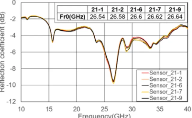
The measured reflection coefficient at the input of the sensing device before nuclear irradiation is reported in Figure 3. As expected, the resonant frequency Fr0 (at 26.6 GHz) is quasi-identical for all the devices manufactured on the same glass substrate, with a difference of less than 100MHz between all the measurements. These results experimentally validate the reliability of the technological process flow for fabricating the nuclear radiation sensors.
Figure 3. Measured reflection coefficient vs frequency at the input port of 5 nuclear radiation sensors (called here 211, 2, 6, 7 and
21-9) before nuclear irradiation. B. Sensitivity to nuclear irradiation
The nuclear radiation sensors have been irradiated using 6MeV focused e-beam providing by electron accelerator with doses of 20kGy. Few days after irradiation, the radiation sensitivity ΔFr/Fr0 has been characterized at atmospheric pressure. After irradiation, a shift ΔFr of the resonant
frequency Fr0 is observed, as reported in [4]. The combination of the following reasons explains the difference between the frequency shifts (between 3% and 8.4%) obtained for a priori identical sensors:
• The non-reproducibility of physico-chemical properties of the PE. This effect is under investigation with specific test equipment;
• The non-identical membrane deflections for all sensors due to different values of membrane thickness in the etched parts. Thickness deviation of 2% was measured and this effect can then be excluded;
• The non-identical surface interaction between the microwave resonator and the non-etched Si membrane. Due to the used etching technique (liquid etching with Tetramethylammonium hydroxide), the membrane shape is octagonal with dimensions smaller than those designed on the mask. As a consequence, the current density on the planar resonator is lower when using this membrane shape than the current density obtained with a square membrane (Figure 4) and therefore, the electromagnetic interaction between the membrane and the planar resonator is smaller for the octagonal membrane. Electromagnetic simulations reported in Figure 5 indicate that membrane shape has a small impact on the resonant frequency;
Figure 4. E-field distribution on the surface of the CPW resonator with octagonal and square membranes for a gap=0.5µm.
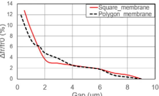
Figure 5. Frequency shift depending of membrane position for two membrane geometries: square and polygon (octagonal) membranes.
• The inclination of the membrane may differ from one sensor to another. This is due to different mechanical stresses and to non-identical manufacturing defects of sensors. Various inclinations (from 0 to few microns) are possible in practice and may have a significant impact on the sensor sensitivity when the membrane is very close to the resonator, as it can be observed from
Figure 6. This effect can be an explanation for the non-reproducibility of sensitivity for the different sensors.
Figure 6. Simulated resonant frequency shift vs the air gap between the membrane and the planar microwave resonator.
The nuclear radiation sensors have been irradiated in July 2014. The last microwave measurements performed in January 2017 indicate that gases are still present in the PE cavity (Figure 7). The resonant frequency evolution after irradiation is reported in Figure 8. According to this figure, sensor 21-1 keeps the same resonant frequency after 2.5 years and consequently, presents a long term hermeticity.
Figure 7. Measured reflection coefficient S11 vs frequency for 3 nuclear radiation sensors (21-2, 21-7 and 21-9) after irradiation.
Figure 8. Measured resonant frequency shift normalized to Fr0 (in %) versus time for 5 nuclear radiation sensors (21-1, 21-2, 21-6, 21-7 and 21-9).
III. APERTURE COUPLED MICROSTRIP TRANSITION FOR
FEEDING THE PLANAR MICROWAVE RESONATOR
To overcome some technological issues related to the fabrication of CAVITY 1 and CAVITY 2, the new architecture shown in Figure 9 is proposed. This architecture is composed of one cavity only. The design is based on a microstrip
transition for feeding a microwave resonator. This solution does not require coplanar access ports for probe measurements, and presents four main advantages: 1) the absence of the non-uniform Si membrane that could alter the reproducibility of mechanical behavior; 2) the simple technological process without glass-Si-glass bonding; 3) the protection of the resonator inside the hermetic cavity and 4) the compact packaging of the sensor.
Figure 9. Side-view of microstrip aperture coupled to a microwave planar resonator.
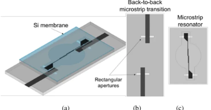
The structure is composed of a Si membrane above a microstrip resonator and a back-to-back microstrip transition, as shown in Figure 10.
(a) (b) (c)
Figure 10. (a) 3D view of the proposed design on the right; (b) top view of the back-to-back microstrip transition and (c) the microstrip resonator.
A sensitivity analysis has been done to validate the new design performances and is presented in Figure 11. For an air gap (distance between the Si membrane and the planar resonator) between 10µm and 0.5µm, the microstrip technology offers a convenient linear response. However, when the membrane is very close to the resonator, coplanar configuration offers higher sensitivity than the microstrip one.1
Figure 11. Simulated frequency shift versus air gap for a planar microwave resonator using microstrip and coplanar (CPW) technologies.
The proposed architecture including both the microwave microstrip resonator and a 100µm thick Si membrane has been manufactured (see Figure 12).
a) b)
Figure 12. a) Manufactured sensing prototype using microstrip technology for fabricating the planar resonator; b) Sensor packaging.
Measurement results are reported in Figure 13. The measured resonant frequency is 22.8GHz and is in good agreement with the simulated frequency using HFSS software (simulated resonant frequency of 22.5GHz).
Figure 13. S parameters of the microstrip resonator using coaxial connectors
IV. REMOTE READING OF NUCLEAR RADIATION SENSOR
The remote interrogation of the fabricated nuclear radiation sensors using a FMCW (Frequency-Modulated Continuous-Wave) microwave radar is proposed in this section. This radar technique is described in details in [5] and allows obtaining radiation information by limiting human intervention at the sensors location. To illustrate the feasibility of such measurement, the radiation sensor is loaded by an impedance of 50Ω at the input port and a horn antenna through a delay line (effective length of 4.0 meters) at its output port. Since the horn antenna is located at 3.5 meters from the radar, the electromagnetic (EM) backscattering from the sensor is expected at the range of 3.5 + 4.0 = 7.5 meters. This backscattering generates an EM echo with an amplitude (or level) depending directly on the reflection coefficient of the sensor input port. This echo is called sensing (or antenna)
mode [6]. To detect the sensing mode, the FMCW radar
transmits a chirp at a carrier frequency of 23.8GHz and a triangular frequency modulation with a frequency sweep rate of 400MHz/ms. The 2GHz bandwidth allows achieving a theoretical depth resolution of 7.5cm. A lens antenna
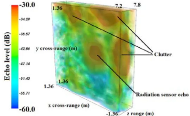
(beamwidth of 6°) is used as transmitting antenna (Tx-antenna). The output microwave power is 20dBm (100mW). A standard horn antenna (Rx-antenna) is used for receiving the backscattered signal. The radar system is mounted on a rotating platform performing a 3D mechanical beamscanning of ±10° in azimuth and ±10° in elevation with an angular step of 1°. This system allows pointing the Tx-antenna main lobe in 441 directions and consequently, recording 441 beat frequency spectra (1 spectrum per direction). Figure 14 displays the resulting 3D representation of the echo level for the nuclear radiation sensor. The sensing mode is detectable among multiple undesirable echoes (clutters) generated by objects surrounding the sensor. Figure 15 displays an example of 2D contour analysis using a marching square algorithm in a cut plane z=7.50m. On each contour the echo level is of -40dB. The echo levels inside the contour n°4 are generated by the sensing mode and consequently, only these echoes will be taken into account for the remote derivation of the measured radiation level. The highest echo level eMax is then found in
contours corresponding to the position of the sensor for each cut-plane. The estimator eMax may theoretically vary from
-38dB to 23dB (that is, a full-scale measurement range of 15dB). However, in the radar frequency band (i.e., between 22.8GHz and 24.8GHz) the S-parameters variation of the fabricated sensor does not allow reaching this large full-scale measurement range. Nevertheless, a small but measurable echo difference of 1dB was obtained before and after nuclear irradiation of sensor prototype.
Figure 14. 3D echo level display of the nuclear radiation sensor. The radiation sensor echo is surrounded by undesirable echoes (clutters).
Figure 15. 2D display of the nuclear radiation sensor in a cut-plane at z=7.50m. A contour analysis is performed for an initial level of -40dB. The contour No 4 corresponds to the nuclear radiation sensor echo.
V. CONCLUSION
In this work, new experimental results obtained from passive coplanar sensors for the remote measurement of nuclear radiation has been reported. The applied technological process allows the fabrication of long-term hermetic cavities. However, the sensors fabricated on the same glass substrate did unfortunately not offer the same sensitivities to nuclear irradiation. Based on technological considerations, explanations have been reported to interpret such undesirable differences and a promising solution to overcome this issue has been proposed. It consists of using a microstrip microwave resonator (instead of a CPW resonator) and a classical coupled aperture microstrip transition. This new solution is very convenient because it does not require probe contact for measurement purposes and it needs one cavity only. The new microstrip sensor has been wirelessly interrogated from a microwave FMCW radar. Works are under way for enlarging the full-scale measurement range of the proposed nuclear radiation sensors.
VI.ACKNOWLEDGMENTS
This work was performed in the framework of CARANUC project funded by Occitanie Region. It was partly supported by LAAS-CNRS micro and nano-technologies platform, member of the French RENATECH network and by H2020-ICT Project GateOne (WP DOSIRA). The authors want also to thank Wroclaw University for providing technological support and NCBJ for e-beam irradiations.
VII.REFERENCES
[1] J. Barthe, “Electronic dosimeters based on solid state detectors”, Nuclear Instruments and Methods in Physics Research Section B, Volume 184, Issues 1-2, September 2001, Pages 158-159.
[2] I. Augustyniak, P. Knapkiewicz, K. Sarelo, J. A. Dziuban, E. Debourg, M. OLszacki, P. Pons, “Micromechanical high-doses radiation sensor with bossed membrane and interferometry optical detection”, Sensors and Actuators A: Physical, Volume 232, 1 August 2015, Pages 353-358. [3] E.Debourg, A. Rifai, I. Augustyniak, M. Matusiak, M. Olszacki, P.
Knapkiewicz, J. Dziuban, H. Aubert, P. Pons. “High doses wireless radiation sensor using electromagnetic transducers”, European Microwave Conference (EuMC), Paris, 2015 France, pp. 383-386. [4] M. M. Jatlaoui, F. Chebila, P. Pons, H. Aubert, “Working Principle
Description of the Wireless Passive EM Transduction Pressure Sensor”, European Physical Journal – Applied Physics, Volume 56, N°1, October 2011.
[5] E Debourg, J Philippe, I Augustyniak, P. Knapkiewicz, J. Dziuban, H Aubert, P. Pons. “Wireless Hydrogen Pressure Dosimeter for Nuclear High Dose Monitoring”, 2016 IEEE Sensors, Orlando, FL, 2016, pp. 1-3.
[6] D. Henry, H. Aubert and P. Pons, “Wireless passive sensors interrogation technique based on a three-dimensional analysis”, 2016 46th European Microwave Conference (EuMC), London, 2016, pp. 49-52.
[7] R. F. Harrington, “Theory of loaded scatterers”, Proceedings of the Institution of Electrical Engineers,, vol. 111, no. 4, pp.617-623, April 1964.