* Author to whom correspondence should be addressed.
Selected paper from the 13th European Conference on Biomaterials, Go¨teborg, Sweden.
JO U R N A L O F M A T E R IA L S S C I E N C E : M A T E R I A L S I N ME D I C IN E 8 ( 19 9 7 ) 89 1 — 8 9 6
Topographical characterization and microstructural
interface analysis of vacuum-plasma-sprayed
titanium and hydroxyapatite coatings on carbon
fibre-reinforced poly(etheretherketone)
S. - W . H A * , A . G I S E P , J. M A Y E R, E . W I N T E R M A N T E L
Biocompatible Materials Science and Engineering, Department of Materials, ETH Zu¨rich,
Wagistrasse 23, CH-8952 Schlieren, Switzerland
H. G R U N E R
Medicoat AG, Gewerbe Nord, CH-5506 Ma¨genwil, Switzerland
M . W I E LA N D
Laboratory for Surface Science and Technology, Department of Materials, ETH Zu¨rich,
Soneggstrasse 5, CH-8092 Zu¨rich, Switzerland
In the present study, topographical characterization and microstructural interface analysis of vacuum-plasma-sprayed titanium and hydroxyapatite (HA) coatings on carbon fibre-reinforced polyetheretherketone (CF/PEEK) was performed. VPS-Ti coatings with high roughness values (
R
a"28.29$3.07lm,R
z"145.35$9.88lm) were obtained. On this titanium, intermediate layer HA coatings of various thicknesses were produced. With increasing coating thickness, roughness values of the HA coatings decreased. A high increase of profile length ratio,L
r, of the VPS-Ti coatings (L
r"1.45) compared to the grit-blasted CF/PEEK substrate (L
r"1.08) was observed. Increasing the HA coating thickness resulted in a reduction of theL
rvalues similar to the roughness values. Fractal analysis of the obtained roughness profiles revealed that the VPS-Ti coatings showed the highest fractal dimension ofD
"1.34$0.02. Fractal dimension dropped to a value of 1.23–1.25 for all HA coatings. No physical deterioration of the CF/PEEK substrate was observed, indicating that substrate drying and the used VPS process parameter led to the desired coatings on the composite material. Cross-section analysis revealed a good interlocking between the titanium intermediate layer and the PEEK substrate. It is therefore assumed that this interlocking results in suitable mechanical adhesive strength. From the results obtained in this study it is concluded that VPS is a suitable method for manufacturing HA coatings on carbon fibre-reinforced PEEK implant materials1. Introduction
Plasma-spraying has become an established method for the manufacturing of calcium phosphate coatings for clinical applications [1—4]. High reproducibility and economic efficiency of the process are outstanding advantages. By variation of process parameters, such as particle-size distribution, spraying distance and the power-level of the plasma coating density, morpho-logy, composition and crystallinity can be varied. The vacuum-plasma-spraying (VPS) technique enables the preparation of coatings of a broad variety of coating materials, including oxygen-sensitive materials like titanium. Dense, crack-free and crystalline HA-coat-ings are achieved with the VPS technique. Many stud-ies of plasma-sprayed HA coatings on metallic
substrates have been performed and described in the literature [5—9]. However, only a few studies exist concerning the application of the VPS process on thermoplastic polymers and composite materials. In this investigation, a systematic approach for the ap-plication of the VPS process on pure and carbon fibre-reinforced PEEK has been chosen. Existing tech-nology and know-how for the deposition of crystalline VPS-HA coatings, which have been achieved with metallic substrates [4], were used as a basis for the optimization of the method to the new substrate ma-terial. The objectives of this study were (a) the
develop-ment of an improved process setup for the
applications of VPS on carbon fibre-reinforced PEEK, and (b) the topographical characterization and
TA B LE I VPS process parameters for the preparation of HA coatings on CF/PEEK substrates
Process parameter Value
Chamber pressure 140 mbar
Spraying distance 300 mm
Plasma gas Ar 33 l min~1
Plasma gas He 7 l min~1
Voltage 45 V
Plasma energy 33.8 kW
Powder feed rate 16 g min~1
TA B LE I I Experimental setup of XRD analysis with the PADX diffractometer
Parameter Value
2h 15°—55°
Modus Step scan
Step size 0.02°
Measuring time per step 2 s
Total measurement time 2 h
Voltage 45 kV
Current 45 mA
Wavelength (CuKa) 0.154 06 nm
microstructural analysis of the interface between the composite substrate and the VPS coatings.
2. Materials and methods
2.1. Plasma-spraying parameters
Extruded carbon fibre-reinforced PEEK discs were cut into discs of 10 mm diameter and 4 mm height. The specimens were grit-blasted with alumina, cleaned with ethanol and pure water and dried in a vacuum oven at 200 °C for at least 7 days. The dried specimens were placed in copper sample holders and positioned in the VPS chamber. Programming of the plasma flame movement was performed with the central con-trol unit of the VPS system. An oscillating movement of the plasmaburner was performed to minimize the thermal impact on the substrate. Substrate temper-ature was measured with an infrared sensor. Vacuum-plasma-spraying was carried out with the parameters listed in Table I [10]. In a first step, fine titanium powder with an average grain size of d50"25 lm was sprayed on to the substrates, and subsequently rough titanium powder with an average grain size of d50"120 lm was applied. HA coatings were produc-ed on an intermproduc-ediate layer of titanium as describproduc-ed above, using HA powder with an average grain size of d50"lm. HA coatings of three different thicknesses,
50, 100 and 150lm, were produced. After VPS
coat-ing, the specimens were gently rinsed in deionized water and dried in air.
2.2. Topographical and microstructural interface analysis
2.2.1. Coating morphology
General coating morphology was examined by scann-ing electron microscopy (SEM, Hitachi S-2500C) to analyse coating integrity, porosity and microcracks. Additionally, backscattering electron (BSE) analyses were performed to study the optical density of the VPS-Ti coating on the composite substrate. The sam-ples were coated with platinum in a Balzers SCD 004 Sputter coater before SEM analysis.
2.2.2. Cross-section analysis and coating
thickness determination
Cross-section analysis of the coated samples were per-formed using SEM to analyse the substrate after vac-uum-plasma-spraying and to investigate the interface between the composite substrate and the VPS-Ti-HA coating. For cross-section analysis, the specimens
were cut perpendicular to the coating with a diamond-coated wire saw (Well, Switzerland) and embedded in epoxy resin. Grinding and polishing were performed with a Struers grinding machine to a 4000-grit SiC finish. The coating thickness values of titanium and hydroxyapatite were measured in the backscattering mode in an image analysis system (Voyager, Noran Instruments).
2.2.3. Surface roughness analysis
Roughness of the VPS-Ti and HA coatings was meas-ured by using an optical autofocusing profilometer (Laser UBM). Measurements were performed with a scan length of 6 mm and a point density of 50 points/mm. Roughness values R!, R2, R; and R.!9 (DIN 4762 and 4768) were measured and the arithme-tic means and standard deviations of five measure-ments were evaluated for each specimen. Additionally, profile length ratio, ¸3 of the coatings was determined.
2.2.4. Fractal analysis
Fractal geometry is a natural description for dis-ordered objects [11]. Fractal analyses of the examined roughness profiles were performed with the box counting method, which is the simplest way to evalu-ate fractal dimensions [12]. The surface roughness profile is covered with boxes of side length d. If the profile is completely covered with N squares, the frac-tal dimension, D can be evaluated according to the rules of fractal geometry
N(d)"ad~D (1)
log N(d)"loga!D log d (2)
By continuously changing the magnification scale through changing the size, d, of the boxes, the number of squares, N, covering the roughness profile is counted. The fractal dimension, D, is obtained by plotting log N versus log d. With this method the fractal dimensions, D, of the VPS-Ti and VPS-Ti-HA coatings of different thicknesses were examined.
2.3. Chemical characterization
2.3.1. X-ray diffraction
X-ray diffraction of the VPS-HA coated samples was performed with an X-ray diffractometer (PADX,
Scintag, USA) with CuKa radiation in the
Bragg-Brentano mode. To place the coated sample into the diffractometer, a special sample holding device was
Figure 2 (a) Scanning electron micrographs of the VPS-Ti coatings revealed a very rough surface topography. In the corresponding
back-scattering electron image (b) a complete coverage of the VPS-Ti coatings on the CF/PEEK substrate was observed.
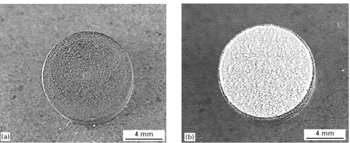
Figure 1 Photographs of a grit-blasted, (a) non-coated and (b) VPS-HA-coated CF/PEEK specimen. The produced VPS-HA coatings
completely covered the underlying substrate.
fabricated, which allowed the coating surface to be placed at the calibrated reference line. The 2h posi-tions of the measured h k l signals were corrected by using a silicon standard. The experimental setup of the XRD investigations are listed in Table II. The X-ray data were collected in the 2h range of 15°—55° in steps of 0.02°.
3. Results and discussion
3.1. Coating characterization
Fig. 1 shows a photograph of a non-coated, grit-blasted CF/PEEK substrate and a VPS-HA-coated specimen. It can be seen that the obtained VPS-HA coatings completely covered the underlying substrate material. In Fig. 2 the SEM and BSE images of the VPS-Ti coatings on the composite substrate are dis-played. The coating showed a rough and porous top-ography built-up by the coarse titanium particles. The BSE image of the VPS-Ti coating revealed a dense titanium layer, suggesting that the fine titanium par-ticles completely cover the underlying composite sub-strate surface. The achieved coating thickness of the
titanium layer varied between 10 and 150lm. Fig. 3
shows the VPS-HA coatings, revealing a smoother topography compared to the rough and porous titanium coating. No cracks were observed in the VPS-HA coatings. Cross-sections of the VPS coatings showed a close contact at the interface between sub-strate and titanium coating (Fig. 4). The titanium layer was fully covered with HA and the close contact between titanium and HA suggested a good mechan-ical interlocking at the HA/Ti interface. The thermo-plastic composite substrate showed no formation of voids and cracks indicating that the coating process had no adverse effects on the substrate material.
3.2. Roughness measurements and fractal analysis
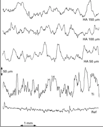
The different roughness profiles of the non-coated and VPS-coated substrates are shown in Fig. 5. Roughness of the VPS-Ti coatings was significantly increased compared to the grit-blasted carbon fibre-reinforced PEEK substrate. The VPS-HA coatings revealed a smoother profile compared to the VPS-Ti coatings.
Figure 3 Scanning electron micrographs of VPS-HA coatings showing the typical morphology with molten particles (a) in an overview and
(b) in higher magnification. No cracks were observed in the VPS-HA coatings.
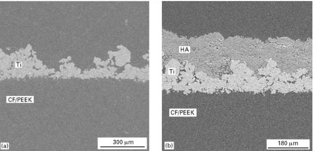
Figure 4 Scanning electron micrographs of cross-sections of (a) VPS-titanium coatings and (b) VPS-hydroxyapatite coatings with an
intermediate titanium layer.
The various roughness values of VPS-Ti and HA coatings measured with an optical profilometer (Laser UBM) are displayed in Table III and in Figs 6 and 7. The rough topography of the VPS-Ti coatings showed average roughness values of R!"28.29 lm, R2"36.61 lm, R;"145.35 lm and R.!9"179.21 lm. With increasing HA coating thickness, roughness values significantly decreased. Profile length ratio, ¸3, was significantly increased from a value of 1.08 to 1.45 after coating the grit-blasted CF/PEEK substrate with titanium. Increasing HA coating thickness resulted in a reduction of the ¸3 values, similar to the roughness
values. The 150lm thick HA coating showed an
¸3value of 1.09.
Fractal analysis of the obtained roughness profiles revealed that the VPS-Ti coatings showed the highest average fractal dimension of D"1.34$0.02. Fractal dimension dropped to a value of 1.23—1.25 after ap-plying the HA coating. No significant difference in fractality was determined between the various HA
coating thicknesses (Fig. 8). The results of the fractal analysis showed that the HA coatings with different roughness values and coating thicknesses have a sim-ilar fractal dimension. Because all HA coatings were formed by the same coating powder using the same process parameters, this could be an explanation for the equivalence of the fractal dimension. The titanium coating powder had a different grain-size distribution and a different morphology resulting in a higher frac-tal dimension compared to the VPS-HA coatings.
The influence of surface topography on biological response is still a matter of investigation. One major difficulty is to find those surface topography para-meters which are relevant for the interactions between the material surface and the surrounding biological environment.
Fractal analysis might be a useful tool to examine these interactions and to elucidate the complex mech-anisms occurring at the implant material surface in contact with the surrounding biological tissue.
Figure 5 Roughness profiles of VPS-Ti and HA coatings obtained
with optical autofocusing profilometer.
TA B LE I I I Roughness values, R!, R2, R; and R.!9 and profile length ratio, ¸3, of carbon fibre-reinforced PEEK substrates before and after coating with titanium and HA using VPS. The VPS-Ti coating showed the highest roughness values. With increasing HA coating thickness, roughness values decreased
Specimen R! (lm) R2 (lm) R; (lm) R.!9 (lm) ¸3 CT/PEEK 4.64$0.69 6.68$1.06 62.71$4.49 53.65$9.02 1.08$0.01 Ti 28.29$3.07 36.61$2.92 145.35$9.88 179.21$9.30 1.45$0.05 HA 50lm 20.18$2.31 26.30$2.65 99.94$8.24 147.19$17.73 1.16$0.02 HA 100lm 13.25$2.95 15.24$1.19 62.71$13.26 80.08$13.41 1.12$0.01 HA 150lm 12.25$2.45 15.30$2.95 62.71$7.80 79.08$16.30 1.09$0.01
Figure 6 Average values ($S.D.) of roughness values R! and R;
(n"5) of VPS-Ti and HA coatings measured with an optical autofocusing profilometer (Laser UBM). The HA coatings have different coating thickness values (Ref"CF/PEEK, HA 50"50lm, HA 100"100 lm, HA 150"150 lm).
Figure 7 Average values ($S.D.) of profile length ratio ¸3 of VPS-Ti
and HA coatings measured with an optical autofocusing pro-filometer (Laser UBM).
Figure 8 Average values ($S.D.) of fractal dimension, D, of VPS-Ti
and HA coatings measured with an optical autofocusing pro-filometer (Laser UBM).
3.3. Chemical composition
The chemical composition of the VPS-HA coatings was investigated by X-ray diffraction. The spectrum showed hydroxyapatite (PDF 9-432) as main
compon-ent and a small b-tricalcium phosphate peak at
2h"31.16° (Fig. 9). No other phases were determined. This is in good accordance to the results obtained on VPS-HA coatings on titanium alloy substrates [13]. It is, therefore, concluded that the changing in the VPS
Figure 9 XRD-spectrum of the VPS-HA coatings showing HA (])
as the main component and small concentrations ofb-TCP.
process for the carbon fibre-reinforced PEEK sub-strate did not affect the chemical composition of the HA-coating, as analysed with XRD.
4. Conclusion
With the VPS coating setup which was optimized for carbon fibre-reinforced PEEK substrates, crack-free titanium and hydroxyapatite coatings were obtained. Cross-section analysis showed that the titanium layer completely covered the CF/PEEK substrates, which is assumed to be an important factor for the biological performance of CF/PEEK. The achieved coating thickness of the titanium layer varied between 10 and
150lm and with this underlying rough titanium
layer, HA coatings of various roughness and profile length ratio values were achieved, depending on coat-ing thickness. No physical substrate deterioration was observed indicating that the applied VPS process parameters led to the desired coatings on the com-posite material. Cross-section analysis revealed a good interlocking between the HA- and titanium coating and between the titanium intermediate layer and the PEEK substrate. It is therefore assumed that this interlocking results in suitable mechanical adhesive
strength. From the results obtained in this study it is concluded that VPS is a suitable method for preparing HA coatings on carbon fibre-reinforced PEEK im-plants. It is suggested that the evaluation of fractal dimensions of VPS-Ti and VPS-HA surfaces and their correlation to cell response may lead to more profound knowledge about the influence of surface structures on in vitro and in vivo biological perfor-mance.
References
1. W . R . L A C E F I E L D ,in ‘‘An introduction to bioceramics’’, edited by L. L. Hench and J. Wilson (World Scientific, Singapore, 1993) pp. 223—38.
2. R . G . T . G E E S IN K ,Clin. Orthop. Rel. Res. 261 (1990) 39.
3. R . G . T . G E E S I N K , K . D E G R O O TandC . P . A . T . K L E I N , Clin. Orthop. 225 (1987) 147
4. H. G R U N E R , in ‘‘Six years experience of hydroxyapatite ceramic coated hip prostheses’’, edited by R. Furlong (Furlong Research Foundation, London, 1991), pp. 97—114.
5. S. D. C O O K , K . A . T H O MA S , J. E . D A L T O N , T . K . V O L K -MA N , T . S . W H IT E C L O U D and J . E . K A Y , J. Biomed. Mater. Res. 26 (1992) 989. 6. K. S Ø B A L L E , K . G O D F R E D S E N , H . B R O C K S T E D T -R A SM U S S E N , P . T . N I E L S E NandK . R E C H N A G E L ,Clin. Orthop. 272 (1991) 255. 7. H. C A U L I E R , J . P . C . M . V A N D E R W A E R D E N , Y . C . G . J . P A Q U A Y , J . G . C . W O L K E , W . K A L K , I . N A E R TandJ . A . JA N S E N ,J. Biomed Mater. Res. 29 (1995) 1061.
8. I . M . O . K A N G A S N I E M I, C . C . P . M . V E R H E Y E N , E . A . V A N D E R V E L DEandK . D E GR O O T ,ibid. (1994) 563.
9. B . C . W A N G , T . M . L E E , E . C H A N GandC . Y . Y A N G ,ibid.
27 (1993) 1315.
10. H. G R U N E R , Implantko¨rper mit Beschichtung, Eur. Pat. 022 853 (1985).
11. B . B . M A N D E L B R O T , ‘‘The fractal geometry of nature’’ (Freeman, San Francisco, CA, 1982).
12. R . B . H E IM A N N ,‘‘Plasma spray coatings’’ (VCH, Weinheim, 1996).
13. S. W . H A , R . R E B E R , K . L . E C K E R T , M . P E T I T M E R -ME T , J . M A Y E R , E . W I N T E R M A N T E L and C . B A E R -L O C H E R ,J. Amer. Ceram. Soc. (1977) in press.
Received 12 May
and accepted 26 May 1997
![Figure 9 XRD-spectrum of the VPS-HA coatings showing HA ( ] ) as the main component and small concentrations of b -TCP.](https://thumb-eu.123doks.com/thumbv2/123doknet/14870778.639751/6.816.78.412.45.255/figure-xrd-spectrum-coatings-showing-component-small-concentrations.webp)
