Order N°: D 73/2019
THESIS
In partial fulfillment of the requirements for the degree of
Option: Mechanics of Materials Submitted by
Prof. Kebdani Said Examiner University of Oran, USTO Prof. Boualem Noureddine Examiner University of Oran, USTO Dr. Chiali Hakim Invitee CHU Tlemcen
Dr. Bendoukha Mohammed Thesis advisor University of Mostaganem
Academic Year: 2018-2019
Prof. Guechichi Hocine President University of Mostaganem Doctoral Committee:
MESBAH Moustafa
University Abd El Hamid Ibn Badis Mostaganem
Faculty of Sciences and Technology FST
Department of Mechanical Engineering
Treatment of Spinal Disorders
using Flexible Constructions
Copyright by MESBAH Moustafa 2019 All Rights Reserved
ii
Acknowledgements
I know by experience that this is the hardest part of a thesis to write. I also know that a couple of months are not enough to develop the cynicism to look back and harshly criticize your work. This is probably the reason for my hesitation in writing these pages. This thesis was developed at the Faculty of Sciences and Technology FST, Department of Mechanical Engineering under the guidance of Dr. Bendoukha Mohamed, to whom I owe gratitude for giving me the opportunity to work in such a challenging research field throughout the years. I would like to thank the president of the doctoral committee Prof. Guechichi Hocine, my examiners Prof. Kebdani Said and Prof. Boualem Noureddine and Dr. Chiali Hakim for providing insightful comments and carefully reviewing my thesis. My examiners not only improved this dissertation with their constructive criticism, but also made a huge impact on my professional development.
I am grateful to all the people who gave their contribution to this work, in particular to: Pr. Moumene Missoum, the wise man, my example, and the mentor who success at teaching me how to study the “spine” appropriately. Other than that, I think he has invented the well-known spinal devices in the world, his guidance (six months) has been the foundation of all that I have learned and done in the field of Spine biomechanics. He helped me with his expertise in the field of biomechanics, thank you for everything.
I would like to thank Professor. Joáo Manuel Tavares from the University of Porto FEUP, Dr. Barkaoui Abd el Wahed from University of Tunis El Manar ENIT and all colleagues, especially of the computational biomechanics group of the University of Tunis El Manar. Their friendship and discussions made the days interesting and enjoyable. Lastly, I would like to thank all my friends that were dragging me away from the computer from time to time and helped me to find answers at the bottom of a glass.
Finally, I am most grateful to all members of my family, for their constant support, patience and encouragement throughout my dissertation, this work is dedicated to them. My Parents, my brothers and my sister appeared to be influenced by my interest in biomechanical engineering for a while, I love you all and I will continue to do my best to be worthy of your support.
iii Table of contents
Table of contents
Acknowledgments ii
Table of Contents iii
List of Figures viii
List of Tables xii
List of Notations xiii
List of Abbreviations xv Abstract xvii Résumé xviii صخلملا xix Introduction 1 Chapter 1: Background 1.1 Introduction 4 1.2 The spine 6 1.2.1 Reference planes 7
1.2.2 Descriptive Anatomy of the Spine 8
1.2.2.1 Bony Vertebrae 9
1.2.2.2 Spinal Ligaments 11
1.2.2.3 Intervertebral disc IVD 14
1.3 Functional Anatomy of Human Lumbar Spine 17
1.4 Experimental methods in spinal biomechanics 18
1.4.1 Spinal loading simulator 19
1.5 Mathematical models of the spine 20
1.5.1 Models considering the elastic behavior 21
1.5.2 Models considering the viscoelastic behavior 22
1.5.3 Biphasic material behavior 23
1.5.4 Direct and inverse problems 24
iv Table of contents
Chapter 2: Treatment of Spinal Disorders Using Flexible Stabilization Constructions
2.1 Degenerative Disc Disease 29
2.1.1 Pathology of Disc Degeneration 30
2.1.2 Changes in the Morphology of the Intervertebral Disc 30
2.2 Spinal disorders 32
2.2.1 Degenerative pathologies 33
2.2.2 Herniated disc 33
2.2.3 Degenerative spondylolisthesis 34
2.2.4 Arthrosis of the joints 35
2.2.5 Lumbar stenosis or narrow lumbar canal 35
2.3 Treatment of spinal disorders 36
2.3.1 Conservative Treatment Options 36
2.3.2 Surgical Intervention 39
2.3.2.1 Spinal fusion or arthrodesis 39
2.3.2.2 Challenges and drawbacks associated with fusion procedure 40
2.4 Posterior Pedicle Fixation-Based Flexibe Stabilization Devices 42
2.4.1 Graf Ligament 42
2.4.2 Dynamic Neutralization System (Dynesys) 43
2.4.3 Bioflex Spring Rod Pedicle Screw System 44
2.4.4 Dynamic Stabilization System (DSS) 45
2.4.5 NFlex dynamic stabilization system 46
2.4.6 Accuflex rod system 46
2.4.7 CD Horizon legacy peek rod 47
2.4.8 Stabilimax NZ 48
References 48
Chapter 3: Biomechanical Response of Lumbosacral Segments under Physiological Functions 3.1 Introduction 52
3.2 Medical, image-based bone reconstruction 53
3.3 CT scanning and 3D mesh model reconstruction 56
v Table of contents
3.3.2 Triangulated Surface Mesh Post-Processing 58
3.3.3 Mesh preprocessing and volume mesh creation 58
3.3.4 FEM modeling based on parametric surface 59
3.3.5 Patch creation for triangular mesh 60
3.3.6 Solid model creation and re-meshing 61
3.3.7 Topological Comparison of Biomodels 62
3.4 Finite element model formulation 62
3.5 Finite Element Model Formulation Workflow chart 67
3.6 The intervertebral disc (IVD) Model Validation 68
3.7 Hyperelastic Model for the Annulus Ground Matrix 70
3.7.1 Hyperelasticity Theories and Continuum Mechanics 71
3.7.1.1 Strain Invariants 71
3.7.1.2 Stress components and the strain energy equation, W 73
3.7.2 Forms and Applications of the Strain Energy Equation 76
3.8 Validation 78
3.8.1 Loading and Boundary Conditions 77
3.8.2 Results 78
3.9 The L4-L5 Model Validation 78
3.9.1 L4-L5 Indiscal pressure IDP and Facet Joint Force FJF validation 78
3.9.2 Loading and Boundary Conditions 81
3.9.3 Model Validation 81
3.9.4 Results 81
3.10 L1-S1 motion segment validation 83
3.10.1 Loading and Boundary Conditions 83
3.10.2 Methods 84
3.10.3 Results 84
3.11 Discussion 86
3.12 Limitations of the FE Analysis 87
3.13 Conclusion 88
vi Table of contents
Chapter 4: Comparative Analysis of Hybrid Flexible Stabilization and Fusion for Degenerative Disease of the Lumbosacral Spine: Finite element Analysis
4.1 Introduction 92
4.2 Materials and Methods 93
4.3 Implant Placements 97
4.4 Results 99
4.4.1 Intersegmental rotation 99
4.4.2 The stresses of different surgical constructs 101
4.4.3 The itradiscal pressure 101
4.4.4 Comparisons of the axial forces of different surgical constructs 102
4.4.5 The cage-endplate stresses of different surgical constructs 103
4.5 Discussion 106
4.6 Significance 107
References 108
Chapter 5: Biomechanical Analysis of Adjacent Segment Level following Hybrid Dynamic Stabilization Topping off Fusion of the Lumbar Spine 5.1 Introduction 110
5.2 Methods and boundary conditions 111
5.2.1 Implanted models Formulation 111
5.2.2 Contact definitions 112
5.2.3 Methods of detection of COR locations 113
5.3 Results 115
5.3.1 Change in Center of Rotation Analysis 115
5.3.2 Strain distributions 116
5.3.3 Bending stiffness 117
5.3.4 Maximum Annulus Stress 118
5.3.5 Facet joint force 119
5.4 Discussion 120
5.5 Summary 122
vii Table of contents
Chapter 6: Anisotropic Response of the Holzapfel’s Constitutive Model for the Lumbar Spine Considering Degenerative Related changes
6.1 Introduction 126
6.2 Methods and materials 127
6.3 Model formulation 129
6.4 Loading and Boundary Conditions 129
6.5 Results 130 6.5.1 ROM results 130 6.5.2 Stress results 131 6.6 Discussion 134 6.7 Conclusions 134 References 135
Conclusions and outlook 137
viii List of figures
List of figures
Chapter 1: Background
Figure 1.1: Average physiological ROM of lumbar motion segments 7
Figure 1.1: Reference planes and axis 8
Figure 1.2: The spine 10
Figure 1.3: The lumbar spine anatomy 12
Figure 1.4: Tensile mechanical behavior of spinal ligaments 13
Figure 1.5: Anatomy of the spine: Ligaments of the vertebral column 14
Figure 1.6: Intervertebral disc. Annular fibers and their orientation 15
Figure 1.7: Components of the vertebrae and the intervertebral disc 16
Figure 1.8: strain rates of the human lumbar annulus fibrosus specimens under tensile loading bundles 16
Figure 1.9: Annulus fibrosus 16
Figure 1.10: Average physiological ROM (in degrees) of lumbar motion segments in principal loading axes. Error bars indicate the normal physiologic limits 19
Figure 1.11: Mechanical testing of human lumbar spine 20
Figure 1.12: Literature review: Correlation between the measured stiffness of the motion segment and the disc morphology 20
Chapter 2: Treatment of Spinal Disorders Using Flexible Stabilization Constructions Figure 2.1: Common intervertebral disc related issues 29
Figure 2.2: Lumbar intervertebral discs fixed in 4% formalin in sagittal section 32
Figure 2.3: Normal and Herniated disc 34
Figure 2.4: X-ray shows the spondylolisthesis 36
Figure 2.5: Stenosis 36
Figure 2.6: Different stabilities. Using the analogy bowl to represent the load–displacement curve of the spine 36
Figure 2.7: A simplified treatment option flow chart for spinal ailment 38
ix List of figures
Figure 2.9: Classification of spinal instrumentation systems 42
Figure 2.10: Graf ligamentoplasty system 43
Figure 2.11: Dynesys device applied on a spinal model 44
Figure 2.12: The Bioflex System 45
Figure 2.7: Dynamic Stabilization System DSS 45
Figure 2.14: NFlex dynamic stabilization system 46
Figure 2.15: The CD-Horizon Legacy PEEK rod 47
Figure 2.16: The Stabilimax NZ 48
Chapter 3: Biomechanical Response of Lumbosacral Segments under Physiological Functions Figure 3.1: Medical imaging-based reconstruction of a vertebral column based on volumetric mesh. Smoothed and decimated polygones of the L5 56
Figure 3.2: 3D model of lumbar spine reconstructed from CT images 57
Figure 3.3: Volumetric mesh created from triangular mesh 59
Figure 3.4: Parametric surface model creation 60
Figure 3.5: Parametric surface model creation 61
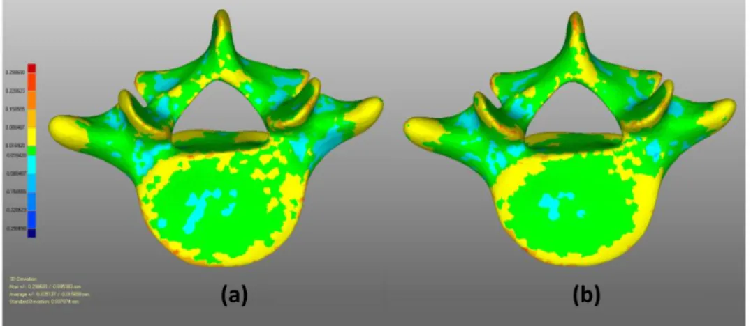
Figure 3.6: The magnitude of 3D deviation of vertebra performed with Geomagic Relaxing 62
Figure 3.7: Finite element model formulation 64
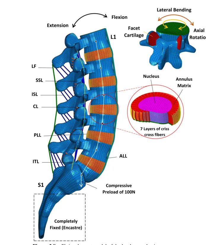
Figure 3.8: Finite element model of the lumbosacral spine 67
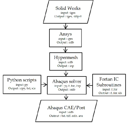
Figure 3.9: Finite Element Model Formulation Workflow Chart 68
Figure 3.10: General plane showing the angles and the stress in that plane resolved in rectangular coordinates 71
Figure 3.11: Cube of unit length subjected to pure deformation to give side lengths of
1,
2 and
3. 72Figure 3.12: Intradiscal pressure against the applied compressive force compared within vitro models 79
Figure 3.13: Vertical displacement against the applied compressive force compared with in vitro models 79
Figure 3.14: Intradiscal pressure of L4-L5 IVD under Combined load Conditions 80
x List of figures
Figure 3.16: FE model validation based on cadaveric in Vitro data 83
Figure 3.16: Comparison between predicted intervertebral rotations results in different spinal levels for the loading cases 85
Chapter 4: Comparative Analysis of Hybrid Flexible Stabilization and Fusion for Degenerative Disease of the Lumbosacral Spine: Finite element Analysis Figure 4.1: Decomposed illustration of FE model in the lumbosacral spine L2-S1 95
Figure 4.2: FE model of the lumbosacral spine post-operative posterior of hybrid surgery 97
Figure 4.3: Whole process of FE model Formulation and analysis Workflow 98
Figure 4.4: Post-operative posterior digital radiographs of the lumbosacral spines with posterior hybrid surgery 99
Figure 4.5: ROM (deg) at the level of fusion, topping off fusion and adjacent level as compared to the intact Spinal 100
Figure 4.6: Von Mises Stress distribution of the Annulus of L3-L4 level 101
Figure 4.7: Intervertebral disc IDP (KPa) at the L2-L3 level 102
Figure 4.8: Axial force in the implant for Fusion 102
Figure 4.9: Stress nephogram of the flexible rods 103
Figure 4.10: Stress and contact area nephograms on cage-endplate interface of L4-L5 104
Figure 4.11: Von Mises stress distribution at the interbody cage for the three models of lumbar stabilization 105
Chapter 5: Biomechanical Analysis of Adjacent Segment Level Following Hybrid Dynamic Stabilization Topping off Fusion of the Lumbar Spine Figure 5.1: FE model of L3-S1 FSU different scenarios 112
Figure 5.2: Posterior digital radiographs and of the lumbosacral spines with posterior hybrid surgery 113
Figure 5.3: Determining the instantenous centre of rotation ICR 113
Figure 5.4: Change in COR for all configurations (mm) 116
Figure 5.5: Predicted maximum strain distribution (10-3) in the disc for Intact, Degenerated and Fusion modes 117
xi List of figures
Figure 5.7: Predicted maximum stress and facet joint forces distribution
for all configurations: Flexion-Extension 119 Figure 5.8: Facet joint loads of L3-L4 level after Hybrid stabilization 119 Figure 5.9: Von Mises Stress distribution of the Annulus of L3-L4 level after
Hybrid stabilization 120 Chapter 6: Anisotropic Response of the Holzapfel’s Constitutive Model for the Lumbar Spine Considering Degenerative Related changes
Figure 6.1: degeneration of the intervertebral disc 128 Figure 6.2: Finite Element Model formulation 129
Figure 6.3: Comparison of intradiscal pressure (IDP) of the Healthy model with experimental results 131 Figure 6.4: ROM of L4-L5 FSU 131 Figure 6.5: Von-Mises Stress distribution obtained from FE Models:
Healthy, Moderate and Severe 132 Figure 6.6: Strain magnitude distribution obtained from FE Models:
Healthy, Moderate and Severe 133 Figure 6.7: Axial stress distribution and compressive strain predictions obtained
from FE Models in the mid-height plane of the IVD from posterior to anterior
midline under Compression (2000N), Flexion and Extension (10 Nm). 133 Figure 6.8: Total strain Energy predictions for the ligaments under all loading
xii List of tables
List of tables
Chapter 3: Biomechanical Response of Lumbosacral Segments under Physiological Functions
Table 3.1: Details of the element types and material properties used in the
FE model 69 Table 3.2: Loading modes using for the different motions 80 Chapter 4: Comparative Analysis of Hybrid Flexible Stabilization and Fusion for Degenerative Disease of the Lumbosacral Spine: Finite element Analysis
Table 4.1: Material properties used in the FE model of lumbosacral spine L1-S1
and the implants 96 Table 4.2: Material properties used in the implants 97 Chapter 5: Biomechanical Analysis of Adjacent Segment Level Following Hybrid Dynamic Stabilization Topping off Fusion of the Lumbar Spine
Table 5.1: Material properties used in finite element model of lumbar spine
Components 114 Table 5.2: Material properties of the seven major ligaments 114 Table 5.3: Mechanical properties of the stabilization devices components 114 Chapter 6: Anisotropic Response of the Holzapfel’s Constitutive Model for the Lumbar Spine Considering Degenerative Related changes
xiii List of notations
List of notations
E
Young’s modulus, MPa
Strain
Poisson’s ratio
Micron, 10-6Cij
Material constants characterizing the hyperelastic strain energy equationsIi
Invariants of the deviatoric of the left Cauchy-Green strain tensorD1
Material incompressibility factorK
bulk modulus of the materialK1
Fiber Stiffness ParameterK2
Fiber Nonlinearity Parameterκ
Fiber Dispersion Parameterσ
Normal StressJ
The material constants for the annulus ground substanceV
Local volume ratioV0
Initial volume ratiol
Direction cosine with respect to the x directionm
Direction cosine with respect to the y directionn
Direction cosine with respect to the z directionS
Total stress on general planeSx
x component of total stress on a general planeSy
y component of total stress on a general planeSz
z component of total stress on a general planeSn
Stress normal to general planeσ
Normal stressxiv List of notations
γ
Shear strainλi
Extension or stretch ratio; i=1, 2, 3 for principal directionsK
Stress invariantD
DisplacementK
Curvature of a polynomialW
WorkU
Strain energy densityF
Force generating simple shear deformationxv List of abbreviations
List of abbreviations
AF NP IVD [∼s] ALL PLL CL FL ITL ISL SSL PDS DSS Dynesys VAS ODI MIS LBP L1 L1/S1 CT DDD DOF FCE [∼s] FEA FEM FSU [∼s] IDP MRI Annulus Fibrosus Nucleus Pulposus Intervertebral DiscAnterior Longitudinal Ligament Posterior Longitudinal Ligament Capsular Ligament
Flavum Ligament
Intertransversal Ligament Interspinous Ligament Supraspinous Ligament
Posterior Dynamic Stabilization Dynamic Stabilization system Dynamic Neutralization System Visual Analogue Score
Oswestry Disability Index Minimally Invasive Surgery Low Back Pain
First Lumbar vertebra Lumbosacral Spine
Computational Tomography Degenerative Disc Disease Degree Of Freedom Fluid Cavity Element Finite Element Analysis Finite Element Method Functional Spinal Unit Intradiscal Pressure
xvi List of abbreviations ASD DS DTO FDA PCU PEEK PET Ti ROM STL UMAT V [∼e] IGES CAD NURBS C3D8 C3D8H F3D4 T3D2 S4R ALIF CCE SED
Adjacent Segment Disease (Deterioration) Degenerative Spondylolysthesis
Dynamic Transition Optima Food and Drug Administration Polycarbonate Urethane Poly Ether Ether Ketone Polyethelene
Titanium
Range of Motion Stereoletheography
User Material; ABAQUS user subroutine Vertebra
Initial Graphics Exchange Specification Computer Aided Design
Non-Uniform Rational Basis Spline
ABAQUS Continuum 3D hexahedral element
ABAQUS Continuum 3D hexahedral Hybrid element ABAQUS 3D Fluid quadrilateral element
ABAQUS 3D Truss element
ABAQUS 4 quadrilateral shell element Anterior Lumbar Interbody Fusion Constraint Coupling Element Strain Energy Density
xvii
Abstract
The mechanism and surgical treatment of lumbar spine pain remain controversial. As the name implies, flexible stabilization is based on the concept of instability as a cause of activity-related. Unfortunately, spinal instability is not well defined and is poorly understood. Spinal fusion has been the cornerstone of surgical treatment for back pain, this procedure has been practiced for almost a century, and generally results in successful clinical outcomes. Although fusion works in the majority of patients, in many cases persistent back pain. Furthermore, accelerated degeneration of the adjacent segment after initial clinical success with fusion surgery is fairly common. The concept of flexible stabilization was developed as a result of fusion’s failure to deliver the wanted clinical result.
The purpose of this thesis is to investigate the treatment of spinal disorders using flexible stabilization constructs. This work aims to find the best stabilization that restores the kinematics of spinal segments of normal movement without overloading the structural elements that govern specific movement using a parametric finite element FE modeling, consequently the basic key in the process of the thesis is the validation work which was carried out by development of computational analogues of the spinal morphologies based on the reconstruction computer tomography CT scan imaging by the creation of detailed Three-dimensional FE model of an intact Lumbosacral segments that mimics the real biomechanical behavior of the human spine.
Flexible rods have been introduced for use with anterior interbody cages to achieve a more successful fusion. The hybrid dynamic stabilization to fusion was introduced to provide special protection against fusion-induced adjacent segment disease including adjacent segment degeneration and adverse effects.
The description of the mechanical behavior of the healthy and degenerative conditions of the intervertebral disc were quantified by developing the mechanical properties annulus fibrosus tissue using an anisotropic constitutive continuum model of Holzapfel as well as developing a realistic description of the nucleus geometry with optimization determination of the requisite material coefficients.
Key words: lumbar spine, flexible stabilization, spinal fusion, finite element, hybrid dynamic stabilization, adjacent segment disease.
xviii
Resumé
Le mécanisme et le traitement chirurgical des douleurs rachidiennes restent controversés. Comme son nom l'indique, la stabilisation flexible est basée sur le concept d'instabilité durant l'activité. Malheureusement, l'instabilité vertébrale n'est pas bien définie et est mal comprise. La fusion spinale reste la pierre angulaire du traitement chirurgical des douleurs dorsales. Cette procédure est pratiquée depuis près d'un siècle et aboutit généralement des résultats cliniques positifs. L’accélération de la dégénérescence du segment adjacent après le succès clinique initial de la fusion est assez commune. Le concept de stabilisation flexible a été développé à la suite de l'échec de la fusion pour fournir des résultats cliniques voulus.
Le but de cette thèse est d'étudier le traitement des troubles spinaux en utilisant des constructions de stabilisation flexibles. Ce travail vise à trouver la meilleure stabilisation qui restaure la cinématique des segments vertébraux du mouvement normal sans surcharger les éléments structuraux qui gouvernent le mouvement spécifique en utilisant une modélisation paramétrique par éléments finis EF, par conséquent la clé de base dans le processus de la thèse est le travail de validation, qui a été réalisée par le développement des analogues informatiques de la morphologie de la colonne vertébrale basée sur la reconstruction d’imagerie médicale tomodensitométrique et la création d'un modèle EF tridimensionnel détaillé du segment lombo-sacré intact pour imiter le comportement biomécanique réel du rachis humaine. Des tiges flexibles ont été introduites pour une utilisation avec des cages intersomatiques antérieures pour obtenir une fusion plus réussie. La stabilisation dynamique hybride à la fusion a été introduite pour fournir une protection spéciale contre la maladie du segment adjacent induite par la fusion, y compris la dégénérescence du segment adjacent et les effets indésirables. La description du comportement mécanique des conditions saines et dégénératives du disque intervertébral a été quantifiée en développant les propriétés mécaniques de la tissue annulaire fibrose en utilisant un modèle continuum anisotrope constitutif de Holzapfel et en développant une description réaliste de la géométrie du noyau avec la détermination de l'optimisation des coefficients matériels requis.
Mots clés: rachis lombaire, stabilisation flexible, fusion spinale, éléments finis, stabilisation dynamique hybride, maladie du segment adjacent.
xix
صخلم
آ ةيل لا موقي نرملا رارقتسلاا نإف ،مسلاا يحوي امكو .لدجلل ةريثم لازت لا ينطقلا يرقفلا دومعلا ملالآ يحارجلا جلاع طاشنلا بابسأ نم اببس هفصوب رارقتسلاا مدع موهفم ىلع ظحلا ءوسل . يرقفلا دومعلا يف رارقتسلاا مدع ، ريغ ددحم موهفم ريغو اديج ، نأ ثيح لا راهصنلاا يكوش لازي لا م دقو ،رهظلا ملالآ يحارجلا جلاعلا يف ةيوازلا رجح و سر جئاتن ىلإ امومع يدؤيو ،نرق نم برقي ام ذنم ءارجلإا اذه ةيئافشتسا راهصنلاا نأ نم مغرلا ىلع .ةحجان عجان يف نم ريثك يف ،ىضرملا ةيبلاغ تلااحلا ظحول ،كلذ ىلع ةولاعو .رهظلا ملاآ رارمتسا لإا ملا طاطحن لا نم لجع ءزج رواجملا مغر يلولأا يريرسلا حاجنلا دعب نرملا رارقتسلاا موهفم ريوطت مت دقو .ام دح ىلإ عئاش راهصنلاا ةحارج يتن تنلا ميدقت يف راهصنلاا لشف ةج ئا ج لاا ةيئافشتس ةبولطملا . لأا هذه نم ضرغلاو ةحورط تابارطضا جلاع يف قيقحتلا وه ءانب مادختساب يرقفلا دومعلا تا ا ي .ةنرم رارقتس فده لضفأ داجيإ ىلإ لمعلا اذه إ رارقتس تايكرح ديعي دومعلا حئارش يرقفلا ةيلكيهلا رصانعلا لاقثإ نود ةيداعلا ةكرحلل مكحت يتلا اه مادختساب ةنيعم ةكرح رظن ي رصانعلا ة ةيهتنملا لابو ،ةجذمنلا يف يف يساسلأا حاتفملا نإف يلات هذه لأا ةحص نم ققحتلا وه ةحورط لا جذومن يجولوفروم نم ةيبوساحلا اهرئاظن ريوطت للاخ نم ا ىلع يرقفلا دومعلا اسأ ةداعإ س يبوساحلا ليكشتلا مادختساب روص لصفم ءاشنإ قيرط نع يعطقملا ريوصتلا ل داعبلأا يثلاث جذومن ل ةينطق تاعاطق ةيزجع يرشبلا يرقفلا دومعلل يقيقحلا يويحلا كولسلا يكاحت يتلا ةميلس . أ دقو د عم مادختسلال ةنرم نابضق تلخ أ صافق ا قيقحتل ةيمامأ .احاجن رثكأ راهصن نم فدهلا رارقتسلاا لاخدإ راهصنلاا ىلإ نيجهلا يكيمانيدلا وه ا نع مجانلا ضرملا دض ةصاخ ةيامح ريفوت نع مجانلا راهصنلا بارطضا ةيبلسلا راثلآاو رواجملا ءزجلا . و فص ةيحصلا فورظلل يكيناكيملا كولسلا لأل ةيسكنتلاو رق ا ةيرقفلا ص اهديدحت مت للاخ نم صاوخلا ريوطت ةيكيناكيملا لل يفيللا جيسن ةقلحلل جذومن مادختساب يسيسأت ليفازلوه نم لصاوتم (Holzapfel) عضو نع لاضف ةسدنهل يعقاو فصو ديدحت عم ةاونلا أ ل لثم ةبولطملا داوملا تلاماعم . :ةيحاتفملا تاملكلا ا يرقفلا دومعلا نعلا ،يكوشلا راهصنلاا ،نرملا رارقتسلاا ،ينطقل ا لا رص ةيهتنم رارقتسلاا ، نيدلا ،نيجهلا يكيما بارطضا رواجملا ءزجلا .1 Introduction
Introduction
Lower back pain LBP results in a significant decrease in the quality of life and affects a substantial portion of the world’s population. Currently, the gold standard for surgical intervention is the arthrodesis which involves removing the lumbar intervertebral disc, which is assumed to be causing the pain. This practice has existed for almost a century, and generally results in successful clinical outcomes. However, the lack of flexibility at the fused segments may lead to adjacent segment disease ASD. As a result, Flexible or namely Dynamic stabilization technologies have been introduced as a motion preserving alternative to spinal fusion.
So far, most clinicians like to believe that some form of spinal instability, be it abnormal motion and/or abnormal load sharing is a crucial factor in the pathophysiology of mechanical lower back pain to disc degeneration or facet pain. Thus, flexible stabilization indicates control of motion and/or load sharing of the motion segment, to address instability and the resultant lumbar pain.
The study of spinal flexible implants requires minimal knowledge of the spine, at least in terms of its geometry characteristics, its mechanical properties, the pathologies and surgical procedures associated with it. A better understanding of the biomechanical environment associated with spinal disorders is needed in order to properly assess device performance.
The current dissertation outlines several studies, which evaluated the biomechanics of spinal implants. We have established our dissertation based on several specific aims.
Specific Aim 1: Develop a validated finite element model of the healthy human lumbosacral spine.
The main objective of this dissertation was to develop a better appreciation of the biomechanics of treatment of spinal disorders and evaluate the contemporary treatment strategies through finite element modeling. To reach this objective, a FE model of the healthy human lumbar spine was generated based on the reconstruction of computed tomography CT scan imaging and radiographic apparent.
2 Introduction
In Chapter 3, The basic key in the process of validation was stated by development of computational analogues of the spinal morphologies, by the creation of sophisticated three-dimensional Finite Element model of an intact ligamentous L1-S1 motion segment, that matches the real biomechanical behavior of the human lumbosacral spine and for this purpose, the validation was carried out in all 6 DOF. It has the possibility of representing the realities with a much higher degree of fidelity. Lumbar functional spinal unit (L4-L5) are investigated using finite element method, and the effects of these relationships on the nonlinear moment-rotation predictions are interrogated. Mesh convergence was verified based on kinematic and mechanical predictions, including range of motion ROM and intradiscal pressure IDP.
This effort and the employed methodology are extended to generate a finite element model of the lumbar spine (L1-S1) in Chapter 3, with particular detail attention ascribed to the mesh refinement and validation protocols.
Specific Aim 2: Simulate the implantation of rigid and flexible (dynamic) constructions, and evaluate the changes in biomechanical behavior of the spine compared to the healthy, destabilized and stabilized states.
In Chapter 4, 5, implementation of the flexible, rigid stabilization systems into the validated finite element model is documented, and the effects of lumbar arthroplasty using conventional arthrodesis and innovative stabilization systems are assessed within the framework of the healthy and degenerative states of the lumbar intervertebral disc.
Specific Aim 3: Develop a nonlinear, anisotropic, constitutive relationship for the mechanical behavior of degenerated human annulus fibrosus AF, and implement this into the previously developed finite element model of lumbar spinal functional unit
Degenerative disc disease is a major source of low back pain. It is hypothesized to significantly alter the biomechanics of the lumbar spine both at the tissue and motion segment (multi-vertebral) levels. However, explicit correlations between the former and the latter has not been established, and this critical link is only possible through modeling the intervertebral disc tissue behavior within a constitutive framework and implementing it in a finite element model of the lumbosacral spine.
3 Introduction
In Chapter 6, anisotropic Holzapfel’s constitutive models are implemented into the validated finite element model of a lumbar functional spinal unit L4-L5 in order to simulate degenerative disc disease DDD (that is developed and validated in Chapter 3), and the effects of degeneration on local and global biomechanics of the spinal motion segments are reported.
The Laboratory of Numerical and Experimental Modeling of Mechanical Phenomena LMNEPM since couple of years has started research in biomechanical modeling. This laboratory activity was initiated by the creation of the Muscoloskeletal biomodel in 2014 by respectively developing detailed models of the lumbar spine, and subsequently thoracic and cervical spine. The advantages of these modeling are in particular a perfect reproducibility and the parameterization of the model which makes it possible to understand the behavior of the spine. The Laboratory of LMNEPM has been at the heart of the development of a personalized biomechanical finite element model, and the surgical procedure that can be associated with it.
Finally, we have endeavored to show the relevance that this type of modeling can offer the biomechanical understanding of "implant-patient" interactions.
4 Chapter 1: Background
Chapter 1:
Background
1.1 Introduction
The mechanical behavior of the human spine is characterized by remarkable diversity. On the one hand its flexibility allows a wide range of mobility. The thoracic and the lumbar part of the spine contribute up to sixty degrees to forward bending, fifty degrees to side bending and approximately the same amount to rotation. On the other hand, the spinal column can sustain internal compressive forces of a multiple of the body weight. This broad range of functionality is based on twenty-four mobile vertebrae which interact with each other in a complex system of facet joints, intervertebral discs, and ligaments. The gel like intervertebral disc transfers loads between the vertebral bodies and also absorbs energy from vibrations and impact situations. Due to its complex structure and the proximity of the spinal cord, which is surrounded by the vertebrae, surgical interventions of the spine are particularly delicate. However, such interventions may become necessary for indications such as degenerated discs, unstable segments or severe cases of spinal deformities. A bony fusion, which is also called arthrodesis, is the widely accepted standard treatment for these indications. The purpose of an arthrodesis is to mitigate or eliminate the pain that comes from the movement of degenerated discs or joints. In the case of spinal deformities, a fusion maintains the spine in the corrected position or prevents the progression of the deformity.
The first spinal fusion was performed in 1911 for the treatment of spinal tuberculosis by both Hibbs and Albee. Three years later, Hibbs performed the first spinal fusion surgery for scoliosis treatment. Yet it was only in 1929 that Chandler adopted spinal fusion for the treatment of lower lumbar back pain. The vast majority of fusions performed nowadays are for the treatment of back pain, due to its high prevalence, whereas spinal deformities account for only a small fraction.
5 Chapter 1: Background
improve the fusion of the bones. Pedicle screws allowed for the attachment of rods to stabilize the spine posteriorly. Anterior stabilization can be advantageous in some cases, which is achieved with plates mounted to the vertebral bodies, or intervertebral cages. A review of the literature shows that there was a statistically significant increased fusion rate in instrumented surgeries, compared to noninstrumented procedures [4]. Nevertheless, the application of spinal fusion has been controversially discussed in the last three decades, especially for the treatment of degenerative diseases. This is mainly due to the fact that follow up studies generally do not report a significant improvement in the clinical results with instrumentation [4]. Regardless of which indication the spinal fusion relies on, there are other concerns: adverse effects on adjacent segments. Biomechanical studies have shown that the relative immobility of the fused segments changes the mechanical environment [7, 20]. The drastic increase in stiffness of the fused segment consequently leads to increased motion and stress concentrations in adjacent levels [13]. In a clinical study, Ghiselli et al. [24] reported that about one third out of 215 patients who underwent lumbar fusion surgery had degenerated adjacent segments ten years after surgery. Gillet et al [26] reported similar results in a follow-up study up to fifteen years after initial surgery. 41% of the patients showed signs of degeneration, 20% required corrective surgery. However, there is still a controversy whether the adverse effects are just the naturally progressing degeneration or if it is a consequence of the fusion.
Arthroplasty is an alternative to spinal fusion. Motion preserving implants for the treatment of degenerative disc disease have been available for about twenty years. The first long-term clinical results suggest that adjacent level effects are less frequent, compared to spinal fusions. Two recent studies [8, 21] with about 100 patients and a follow-up of at least ten years reported that the rate of adjacent levels requiring surgical intervention was 2.5%, and 5%, respectively. These results support the hypothesis that adjacent level effects are due to the spinal fusion and not due to the natural progression of the degeneration.
Motion preserving treatment of spinal deformities is even more challenging than for degenerative diseases, mainly because not only one segment, but a big portion of the spine is affected. The only non-fusion treatment is currently available for early-onset scoliosis which is a term used for deformations at children under the age of five. The
6 Chapter 1: Background
principle of the treatment is to use a growing rod which allows for spinal growth and corrects the curvature. Each lengthening is performed in a surgical procedure. However, many patients require a definite fusion, once they reached a certain age or size. For adolescent idiopathic scoliosis, which is the most common form of scoliosis, a fusion of a big part of the spine still is the only way to correct severe curvatures and prevent progression.
Theoretically, fusionless or mainly the flexible stabilization treatment strategies have the advantage of preserving motion, thus maintaining the functionality of the spine, and allowing for a physiologic growth of infantile and adolescent patients. Furthermore, the degeneration of adjacent levels may be reduced as this effect seems to be strongly influenced by the fusion of one or more segments. However, the development of more advanced implants and treatment strategies also requires a more detailed knowledge of the pathological and healthy mechanical properties of the spine. The mechanical behavior of a fused segment is based on static, load sharing principles. Motion preserving designs also require a profound knowledge of the kinematic and dynamic properties of the spine in order to properly characterize the in vivo performance of the implant.
This chapter outlines to the objectives of this thesis. A brief overview of the functional anatomy of the spine explains how its mechanical behavior is related to its main anatomical components and structures, i.e. ligaments, intervertebral discs and facet joints. The state-of-the-art experimental methods in spinal biomechanics are then reviewed and their advantages and disadvantages are discussed. Beside experimental data, mathematical models give important insight into the behavior of the spine. A review of numerical models shows which research questions can be addressed and which constitutive laws are used to model the different anatomical structures of the spine. Mathematical models can be solved in two ways: If the mechanical properties are given the solution can be determined, which is called direct problem. If the mechanical properties are to be computed based on experimental data, an inverse problem has to be solved. In the last section of this chapter the objectives and structure of this thesis are presented.
1.2 The Spine
7 Chapter 1: Background
mechanics. It aims to familiarize the reader with the different clinical terms.
After a quick presentation of the reference plans for the anatomical description of the human body, we will focus on the descriptive anatomy of the healthy lumbar spine by deliberately limiting ourselves to the osseoligamentous system.
1.2.1 Reference planes
The study of the human body is based on the fundamental planes of space (Figure 1.1):
• Sagittal planes: these are vertical planes oriented in the anteroposterior direction. The median sagittal plane passes through the axis of the body and divides it into two right and left side
• The coronal (frontal) planes: The coronal plane is the frontal plane passing through the axis of the body, it defines the ventral and dorsal sides of the body.
• The axial (horizontal) planes: they are perpendicular to the two others and cross the body transversely.
8 Chapter 1: Background
1.2.2 Descriptive Anatomy of the Spine
The spine, or vertebral column, consists of a movable column of twenty-four free bony parts and a fixed column formed of welded or fused vertebrae which are connected to each other in an elastic system, consisting of intervertebral discs and ligaments: the sacrum and the coccyx. It is the mast of fixation of many muscles essential for the posture and the locomotion and ensures the protection of the spinal marrow located in the vertebral canal. It supports the head and transmits the weight of the body to the joints of the hip. About 70 cm long in men (60 cm in women), its decrease can reach 2 cm when standing
Figure 1.2: The spine [67].
The vertebrae can be divided into an anterior and a posterior part. The anterior part consists of the vertebral bodies, which are piled one upon the other, thus forming the
9 Chapter 1: Background
vertebral column. The pedicles, two lamina and seven processes make up the posterior part (Figure 1.3).
The backbone is bent in the sagittal plane. It presents two primary curvatures (concave forward), as called kyphosis, to the level of the thoracic spine and sacrum, as well as two secondary curvatures (concave behind) named lordosis to the level of the cervical spine and lumbar.
The spine can be grouped in five parts (Figure 1.2): The cervical spine constituted of 7 vertebrae.
The dorsal spine (or thoracic) constituted of 12 vertebrae. The spine lumbar (or lumbar) constituted of 5 vertebrae. The sacral spine (or sacrum) and the coccyx.
1.2.2.1 Bony Vertebrae
The two major components of the vertebrae are the cortical and trabecular bone. While the former is significantly stiffer and denser, the latter has a sponge-like porous structure which produces a globally more compliant behavior. Several studies have shown that aging leads to different levels of reduction in the solid volume fraction in trabecular bone, and, in severe cases, this leads to osteoporosis. Adams et al [46]. Moreover, physiological loading is known to affect the bone remodeling process, with the major trabecular orientation coincident with the principal loading directions. Freiberg et al [49]. The orientation of the trabeculae shows a clear vertical and horizontal alignment. The pedicles and the lamina form the neutral arch, which en- closes the spinal cord. From the neural arch, the spinous process projects backwards, the two transverse processes project to the side. These three processes serve as attachment and lever arms for ligaments and muscles. With two superior and two inferior articular processes, the vertebrae interact with adjacent levels (Figure 1.4). Mechanically, the anterior vertebral column can sustain compressive forces, while the posterior parts, which are connected to each other only by ligaments, can only sustain tensile forces.
In the anterior column, a stiff cortical shell encloses a trabecular core, and this structural feature becomes especially advantageous under compressive loads. The cortical endplate distributes the load almost uniformly over the trabecular bone, providing additional support at the radial extrema. The posterior elements have an extremely
10 Chapter 1: Background
complex geometry, and the “spinal canal” encompasses the volume between these elements and the vertebral bodies (Figure 1.3). This provides a physical, protective environment for the spinal cord. A total of four facets in the inferior and superior regions form the zygapophyseal joints through articulation with superior and inferior adjacent vertebral levels.
11 Chapter 1: Background
Bilateral transverse processes and the pedicles at the posterior extremities serve as ligament insertion sites, transmitting force between each level and improving stability.
The reduction in the bone quality in many cases is followed by endplate fractures or critical damage on the vertebral bodies, preventing the vertebra from carrying out its primary load-carrying function. Bogduk [52]. Bone cement injection and vertebroplasty are current techniques of surgical intervention which seek to provide immediate stability to the spine.
The aforementioned types of bone tissue are known to undergo infinitesimal deformations in vivo during the activities of daily living. Therefore, a simplistic approach such as linear elasticity is sufficient for describing the physiological mechanical response of these tissues. Crawford et al [51]. Orthotropic and fully isotropic constitutive relationships have been proposed, and a large range of elastic moduli values are reported in the literature.
1.2.2.2 Spinal ligaments
Spinal ligaments have a significant effect on the mobility of motion segments, and, therefore, are crucial for understanding and predicting spinal biomechanics. Zander et al [56]. Similar to tendons, ligaments primarily consist of Type I collagen, elastin, PGs and water with minor amounts of other proteins and different types of collagen. Panjabi et al [17]. With the collagen fibers aligned in the usual loading direction, their mechanical behavior is highly anisotropic. Transverse isotropy is a sufficiently accurate model to describe and model this behavior. Woo et al [60].
The presence of the collagen fiber results in a highly nonlinear static tensile behavior and increases the global strength of the tissue. The mechanical properties of spinal ligaments have been quantified in numerous studies in the past, and substantial differences are observed between the responses of different ligaments. Zander et al [56] (Figure 1.4).
There are seven major spinal ligaments that connect the vertebral bodies and the posterior elements in the lumbar region: Anterior longitudinal ligament (ALL) runs through the entire spine from the sacrum to the cervical region, inserting into the anterior surfaces of the vertebral bodies and covering their associated intervertebral discs. Similarly, the posterior longitudinal ligament (PLL) extends in the same range in the
12 Chapter 1: Background
inferior – superior direction, inserting into the posterior surfaces of their associated vertebral bodies along the spinal canal (Figure 1.5).
On the posterior side of the spinal canal, the ligamentum flava (LF) connect the laminae of each vertebral body to its subsequent inferior and superior levels. Likewise, the Intraspinous ligament (ISL) inserts into spinous processes at the inferior and superior ends and supraspinous ligament (SSL) inserts into the posterior edges at each level. Capsular ligaments (CL) provide additional stability around the facets, covering the entire zygapophyseal joint. And the intratransverse ligaments intratransverse ligaments (ITL) connect the costal process of two adjacent vertebra.
Ligaments are connective tissues that are characterized by a preponderance of collagen fibres and a small content of ground substance, cells and fluid. Thus, the mechanical behaviour reflects the combined properties of an elastic solid and a viscous fluid: Ligaments are viscoelastic. At low strain rates, the viscous element has a negligible effect, so that the tissue behaves predominantly like an elastic structure.
Figure 1.4: Tensile mechanical behavior of spinal ligaments. Figure reprinted from Ayturk et al [69].
The collagen fibers, arranged in parallel bundles, are responsible for the mechanical properties. The tensile strength of ligaments is therefore much bigger in the longitudinal direction than in orthogonal directions. The anterior longitudinal ligament stretches along the front side of the vertebra body (Figure 1.6). With its deep fibres it connects adjacent vertebral bodies and with its superficial fibres it bridges several segments. The collagen
13 Chapter 1: Background
fibres are firmly interwoven with the vertebral bodies, but only loosely connected to the discs. (Figure 1.7).
The posterior longitudinal ligament is situated in the vertebral channel and extends along the backside of the vertebral bodies. The ligament is thicker at the intervertebral disc space than at the vertebral bodies. The superficial layers of the ligament occupy the space between three or four segments, while the deep layers stretch between adjacent vertebrae. The ligamentum flavum extends between the vertebral arches of adjacent vertebrae. It has the highest percentage of elastic fibres of any tissue in the body. Nachemson et al [25]. In upright posture, the ligamentum flavum is under pre-tension. The intertransverse ligament extends between the transverse processes, the interspinous ligament between the spinous processes of adjacent vertebrae. The supraspinous ligament connects the apices of the spinous processes. The superficial layer of the ligament extends over three or four segments, while the deep layers stretch between adjacent vertebrae.
14 Chapter 1: Background
1.2.2.3 Intervertebral disc IVD
Each intervertebral disc is bound to the vertebral bodies which connects two vertebral bodies inferiorly and superiorly through cartilaginous endplates (Figure 1.3). while at the same time allowing them to move relative to each other. To the naked eye, two distinct structures can be distinguished: An outer ring of concentric lamellae of collagen fibres, called annulus fibrosus (Figure 1.3). The central region, called nucleus pulposus, is characterized by a high proteoglycan and thus water content. The cartilaginous endplates are interposed between the bony vertebral bodies and the intervertebral disc itself.
Figure 1.6: Intervertebral disc. Annular fibers and their orientation [17]. Water, collagen, and proteoglycans constitute 90%-95% of the volume of the normal disc [41]. The interplay of these components determines the mechanical behavior of the intervertebral disc. Water and proteoglycan content are highest in the nucleus and lowest in the annulus, whereas the collagen distribution is inverse. The semi-permeable endplates are the primary source for the flow of water into and out of the intervertebral disc. Proteoglycans are negatively charged and thus imbibe water until the hydrostatic pressure is in balance with the external forces. These external forces come from the stresses in the collagen fibres and the active forces applied by ligaments and muscles. If the active forces are increased, fluid is expressed and the proteoglycan concentration and hence the osmotic pressurizes. Alternatively, if the active forces are decreased, fluid is imbibed, and the osmotic pressure falls. The inflow and outflow of water is relevant only for long-term loadings situations. Malko et al [23] reported that the disc volume increased by approximately 10% during overnight bed rest and decreased by 5% after eight hours of walking. When loads to the spine are applied only on a short-term basis, the fluid flow can be disregarded. For such loading scenarios, the intervertebral disc can be considered as a hydrostatic system with membrane-like outer shell.
15 Chapter 1: Background
Nutrients are transported to the avascular discs through these hyaline cartilage tissues via diffusion. Furthermore, these tissues are innervated at the periphery. Aging and/or chemically induced degeneration produces distortion and mineralizes the endplates, which is believed to cause significant pain, as well as increase the risk of endplate fracture and collapse of the intradiscal space. Decreased permeability of the endplates is shown to change the mechanical loading environment inside the disc. Natarajan et al [55]. The elasto- static behavior of this tissue is usually accepted as linear in the non-degenerated discs. Dooris, et al [47]. Schmidt et al [57].).
Figure 1.7: Components of the vertebrae and the intervertebral disc [70].
The core of the intradiscal space, the “nucleus pulposus”, is a proteoglycan-rich viscous material. Negatively charged glycosaminoglycans (GAG), proteoglycans (PG), Type II collagen and water are the main constituents of this tissue. The random orientation of the collagen fibers demonstrates the lack of a structured organization, which consequently generates an isotropic mechanical response. Guerin et al [48]. Furthermore, the negative charges and the presence of PGs result in a high swelling pressure throughout the tissue. This pressure is substantially elevated under the application of compressive loads, and balances itself by creating circumferential “hoop” stresses in the annular lamellae. Adams et al [46].
The anisotropic behavior of the annulus can be described with a transverse isotropy model within a cylindrical coordinate system. Three-dimensional finite element modeling (FEM) approaches allow for the geometric representation of individual fibers, and consequently reinforcement in the preferred orientation. Dooris et al [47]. This approach gives satisfactory results in terms of predicting the global, structural kinetic response;
16 Chapter 1: Background
however, modeling of the tissue-level mechanics of the annulus requires a more rigorous technique. Figure 1.8.
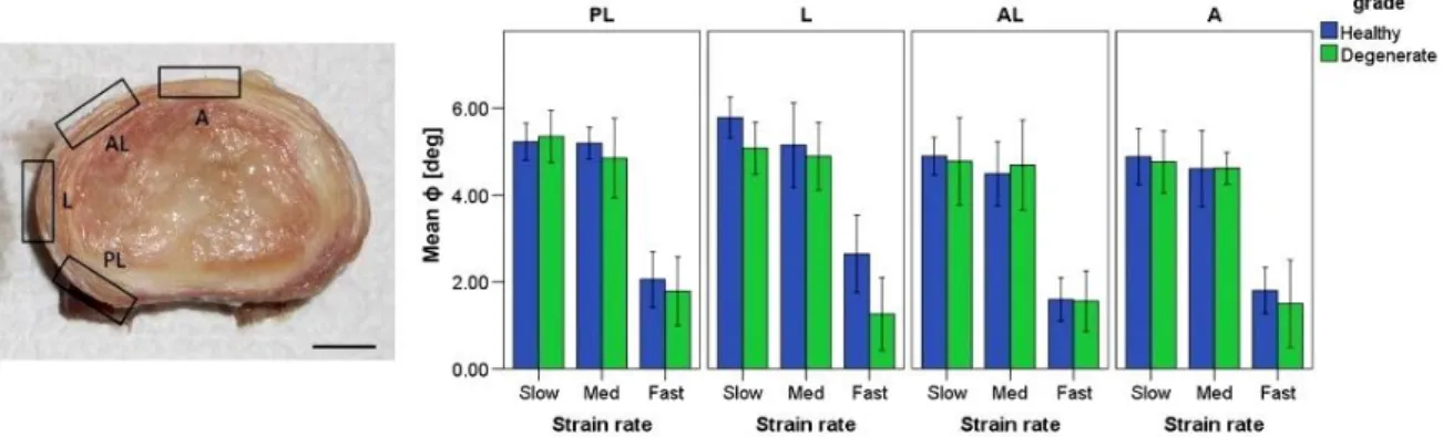
Figure 1.8: strain rates of the human lumbar annulus fibrosus specimens under tensile loading bundles. Pham et al [61].
Spencer’s continuum model for orthotropic materials with multiple fiber families has been employed in previous studies to achieve adequate modeling fidelity (Spencer, 1984). The invariant-based strain energy potentials can be decomposed into individual components of physiological relevance (potentials of the proteoglycan-rich matrix, tissue incompressibility, collagen fibers, etc.) Wagner et al [58]. Guerin et al [48]. in order to simulate the nonlinear mechanical behavior of the annulus fibrosus (Figure 1.9).
Figure 1.9: Annulus fibrosus. a) Cut in the horizontal plane with, four regions are distinguished: ventro-lateral external (VLe), ventro-lateral internal (VLi), dorsal external (De) and dorsal internal (Di), b) Stress-stretch relation of single lamellae. Figure reprinted
17 Chapter 1: Background
The fibres of the annulus anchor into the endplates where they align horizontally. In the lumbar region of the spine, the fibres are arranged in 10-20 concentric lamellae and with alternating orientation in each layer. Commonly, angles of ±30° with respect to the horizontal plane are given in the literature. However, recent studies indicate a more complex situation. Skaggs et al [37] conducted measurements on single lamellae and reported that lamellae from the posterior region have a significantly lower stiffness, than those of the anterior region. This observation is confirmed by Ebara et al [19] who conducted experiments on multi-lamellae specimens. Holzapfel et al [17] reported a significantly higher stiffness of external lamellae than of internal lamellae (Figure 1.9). The orientation of the collagenous fibers was more vertical in the posterior part compared to the anterior regions. Skaggs et al [37] made the important observation that adjacent lamellae with different fiber orientations have the same tensile modulus.
1.3 Functional Anatomy of Human Lumbar Spine
The human lumbar spine is a load bearing structure that carries and transfers the weight of the upper body to the lower extremities through the sacrum and the pelvis. Its mechanical function is not only limited to resisting multi-dimensional loads, but it also confers a certain range of mobility to the upper body via tissue deformation.
The behavior of the lumbar spine under physiologic loads and moments on this multi-joint complex yield different ranges of segmental motion (ROM) at each level (Figure 1.10). However, this load- displacement relationship is commonly nonlinear. Furthermore, relatively small loads generate large displacements due to low tension in the ligaments and the intervertebral disc, resulting in an initially compliant kinetic response known as the neutral zone. The neutral zone (NZ) is regarded as a measure of the joint laxity, and its magnitude can be significantly altered as a result of injuries to the disc such as degeneration or herniation. Mimura et al [54]. Excessive changes in the extent of the NZ have been theorized to be predictors of spinal instability, and therefore, it is an important diagnostic parameter in detecting the aforementioned injuries and diseases.
There is an increasing trend of range of motion in the inferior direction from L1 to S1; however, no significant differences are reported except between the lumbosacral level and all of the intra-lumbar levels. Guan et al [50].
18 Chapter 1: Background
Figure 1.10: Average physiological ROM (in degrees) of lumbar motion segments in principal loading axes. Error bars indicate the normal physiologic limits. Panjabi et al
[17]. 1.4 Experimental methods in spinal biomechanics
The mechanical testing of load-bearing structures of the human body implicates many more difficulties than in classical engineering disciplines. In vitro tests of human spines have the advantage that experiments can be performed under well-defined and controlled conditions and thus allow the investigation of its normal function. However, the limitations of testing specimens outside their physiologic environment are difficult to quantify. When testing human spines, a crucial question to answer is how many spinal segments should be taken. A motion segment is the smallest functional unit, which consists of two vertebrae, the intervertebral disc, and the intervening soft tissue. Some ligaments, as the supraspinous ligament or the anterior and the posterior longitudinal ligaments have superficial fibres which extend across several segments and which have to be dissected. Another issue concerns the support of the specimen and how the loads should be applied. When performing measurements on a single motion segment, neither of the vertebrae is supported physiologically. Intervertebral discs and ligaments have to be kept moist to prevent changes of the mechanical properties. In order to reduce the complexity, muscles are usually completely dissected. Eventually, cadaver spines usually originate from middle aged or elderly people and thus limit the generality of the results.
On the contrary, in-vivo experiments allow measurements under physiologic conditions, and at patients with the pathology of interest. However, due to ethical
19 Chapter 1: Background
reasons the possibilities of performing invasive measurements at the spine are limited. Also, the anatomical accessibility is usually restricted and tests cannot be performed to the fatigue limit. Moreover, boundary conditions of the vertebrae in the in vivo surrounding are unknown.
1.4.1 Spinal loading simulator
In the mid 1970s, the first mathematical models of the human spine were developed to address clinical problems, as sports injuries, scoliosis, and stability of the spine. In order to have data available as input for these models, Panjabi et al [54] performed the first experiments in which the three-dimensional load-displacement behaviour of single thoracic motion segments was determined. To account for more physiologic loading scenarios, one year later, Panjabi et al [31] conducted experiments including axial pre-loading. The axial pre-load originates from the body weight above the segment and from contracting muscle forces that counter-balance the moments from the weight of the body lying anterior of the center of rotation of the vertebrae. Panjabi [28] also emphasized the necessity to examine the behaviour of the spine in three-dimensional space, as before predominantly the uniaxial behaviour of the intervertebral disc has been studied.
Later, the methodology and testing framework has been refined. Panjabi et al [29] suggested to apply pure bending moments in the main anatomical directions when testing spinal segments. This was a pragmatic decision, as physiological loading conditions are not only hard to define, but also difficult to simulate on a test frame. Pure bending moments have the advantage, that the moment loading is constant along the entire specimen. This strategy became the standard for the mechanical testing of spines. A variety of custom-made testing frames, which were called spinal loading simulators, were reported in the literature. These include systems which were based on pulleys and cables [4, 21, 40], stepper motors on a gimbal that can move with a travelling gantry. Wilke et al [42] or Steward Platforms. Stocks et al [39].
Spinal loading simulators were used to determine the mechanical properties of cadaver spines. Due to the high prevalence of low back pain, studies have been conducted predominantly on the lumbar spine. Moment-angle relations were investigated by Guan et al [17], Oxland et al [26], and Panjabi et al [32]. Experiments to
20 Chapter 1: Background
examine the influence of functional spinal structures have also been performed. Heuer et al [15, 16] consecutively removed ligaments, facet capsules, and the nucleus and measured the moment- angle relation after each step.
Figure 1.11: Mechanical testing of human lumbar spine, Frank et al [44].
Figure 1.1 2: Literature review: Correlation between the measured stiffness of the motion segment and the disc morphology, Figure reprinted from Brown et al [5]. 1.5 Mathematical models of the spine
Computational models supplement experimental methods when investigating the mechanics of the spine. As it was mentioned before, in vitro experiments allow to analyze the normal behavior of the spine, but the generality is limited by the availability of
21 Chapter 1: Background
cadaver specimens and the variability among them. In vivo measurements provide information of the spine in its physiologic environment, but are restricted due to the necessity of minimal invasiveness. Numerical models allow to assess internal forces, stresses and strains which cannot be measured in laboratory or in vivo experiments. However, numerical models depend on experimental data as input for constitutive laws and thus incorporate the limitations of the experimental methods. Although modern imaging technology, computing power and advances in theoretical mechanics allow for a more realistic modelling, simplifications.
1.5.1 Models considering the elastic behavior
Models that describe the elastic behaviour of soft tissue establish the vast majority. The first FE model of the human spine was developed by Belytschko et al [3]. The vertebral bodies were defined as rigid beams, while the IVDs were modelled as linear elastic beam elements and the ligaments as linear elastic truss elements. Geometric non-linearities were already accounted for, but it was assumed that the deformation of each element is small. One year later, the first model of the intervertebral disc taking into account the cross-sectional geometry was reported by the same author [2]. The disc was considered as an axisymmetric body and the annulus was modelled as an orthotropic material. A three-dimensional simulation of an entire motion segment considering symmetry about the sagittal plane, including facet articulation was reported by Shirazi-Adl et al [36], the annulus was modelled as a composite material of collagenous fibres embedded in a matrix of ground substance. Few studies did not only take into account non-linear geometry, but also used non-linear stress-strain relations for fibres and ligaments. Embedding discrete truss elements in the ground substance is still a frequently used method for modelling the annulus fibrosus [36, 63, 64].
The development of a general, anisotropic continuum theory allowed to overcome the grid dependency of embedded truss elements. The continuum mechanical approach offers another crucial advantage: The tissue properties can be determined directly from experiments. In contrast to the discrete modelling, the behaviour of the individual constituents, i.e. ground substance and fibers, have to be determined explicitly. For a long time, information on collagen fibrils could only be determined from complete tissues. Only recently, force-displacement curves from isolated, single collagen fibrils
![Figure 1.4: Tensile mechanical behavior of spinal ligaments. Figure reprinted from Ayturk et al [69]](https://thumb-eu.123doks.com/thumbv2/123doknet/13353392.402523/32.892.175.736.578.872/figure-tensile-mechanical-behavior-ligaments-figure-reprinted-ayturk.webp)
![Figure 1.5: Anatomy of the spine: Ligaments of the vertebral column [70].](https://thumb-eu.123doks.com/thumbv2/123doknet/13353392.402523/33.892.267.640.545.1042/figure-anatomy-spine-ligaments-vertebral-column.webp)
![Figure 1.11: Mechanical testing of human lumbar spine, Frank et al [44].](https://thumb-eu.123doks.com/thumbv2/123doknet/13353392.402523/40.892.140.796.218.571/figure-mechanical-testing-human-lumbar-spine-frank-et.webp)
![Figure 2.2: Lumbar intervertebral discs fixed in 4% formalin in sagittal section [28]](https://thumb-eu.123doks.com/thumbv2/123doknet/13353392.402523/52.892.129.814.126.353/figure-lumbar-intervertebral-discs-fixed-formalin-sagittal-section.webp)
![Figure 2.8: Fusion with posterior application of rods and pedicle screws to L4-L5 [50]](https://thumb-eu.123doks.com/thumbv2/123doknet/13353392.402523/60.892.192.728.123.600/figure-fusion-posterior-application-rods-pedicle-screws-l.webp)