HAL Id: tel-01312194
https://tel.archives-ouvertes.fr/tel-01312194
Submitted on 4 May 2016
HAL is a multi-disciplinary open access
archive for the deposit and dissemination of sci-entific research documents, whether they are pub-lished or not. The documents may come from teaching and research institutions in France or abroad, or from public or private research centers.
L’archive ouverte pluridisciplinaire HAL, est destinée au dépôt et à la diffusion de documents scientifiques de niveau recherche, publiés ou non, émanant des établissements d’enseignement et de recherche français ou étrangers, des laboratoires publics ou privés.
Magnetic and transport properties of single and double
perpendicular magnetic tunnel junctions
Lea Cuchet
To cite this version:
Lea Cuchet. Magnetic and transport properties of single and double perpendicular magnetic tun-nel junctions. Condensed Matter [cond-mat]. Université Grenoble Alpes, 2015. English. �NNT : 2015GREAY060�. �tel-01312194�
THÈSE
Pour obtenir le grade de
DOCTEUR DE L’UNIVERSITÉ GRENOBLE ALPES
Spécialité : Physique des Matériaux
Arrêté ministériel : 7 août 2006
Présentée par
Léa CUCHET
Thèse dirigée par Bernard RODMACQ et codirigée par Ricardo SOUSA
préparée au sein du Laboratoire SPINTEC dans l'École Doctorale de Physique
Propriétés de transport et
d’anisotropie de jonctions tunnel
magnétiques perpendiculaires avec
simple ou double barrière
Magnetic and transport properties of single and double perpendicular magnetic tunnel junctions
Thèse soutenue publiquement le 10 novembre 2015, devant le jury composé de :
M. Olivier FRUCHART
D.R. au CNRS, Institut Néel, Grenoble (Président)
M. Stéphane MANGIN
Professeur, Institut Jean Lamour, Nancy (Rapporteur)
M. Dafiné RAVELOSONA
D.R. au CNRS, Institut d’Electronique Fondamentale, Orsay (Rapporteur)
M. Paulo FREITAS
Professeur, Iberian Nanotechnology Laboratory, Braga (Examinateur)
M. Bernard RODMACQ
Ingénieur chercheur CEA, SPINTEC, Grenoble (Directeur de thèse)
M. Ricardo SOUSA
1
REMERCIEMENTS
La soutenance étant terminée, il est temps de passer à la dernière mais non moins importante étape de la thèse : les remerciements. Car ces trois années de thèse n’auraient pas été aussi fructueuses sans les belles rencontres qui les ont ponctuées.
Je commencerai en remerciant chaleureusement mon directeur de thèse Bernard Rodmacq pour m’avoir énormément appris pendant ces trois ans. J’ai beaucoup apprécié notre travail ensemble au quotidien et nos nombreux échanges qui m’ont permis d’acquérir la rigueur nécessaire au travail de développement de matériaux. Merci également à Ricardo Sousa pour m’avoir intégrée à l’équipe MRAM et m’avoir permis d’aller plus loin vers l’application en m’apprenant le processus de nanofabrication. C’est grâce à vous que j’ai pu participer à de nombreuses conférences et je vous remercie tous les deux pour la confiance que vous m’avez accordée dès mes débuts à Spintec.
Je voudrais aussi remercier tous les membres de mon jury de thèse pour avoir accepté d’évaluer ce travail de thèse. Merci à Dafiné Ravelosona et Stéphane Mangin, mes deux rapporteurs, pour le temps qu’ils ont consacré à la lecture de ce manuscrit et leurs commentaires. Merci à Olivier Fruchart d’avoir accepté de présider mon jury et à Paulo Freitas pour ses questions et remarques.
Merci à Stéphane Auffret pour m’avoir tout appris de la machine de dépôt. J’ai énormément appris sur le fonctionnement d’un tel outil à tes côtés. Notre Actemium est une bête capricieuse et qui je crois n’aura jamais qu’un seul véritable maître ! Merci encore Stéphane pour ta sympathie, ça aura été un plaisir de travailler/discuter avec toi de matériaux (ou autre !).
Je remercie également Clarisse Ducruet de m’avoir formée à l’outil de caractérisation Capres et d’avoir toujours suivi avec intérêt mes travaux de thèse. Merci pour toutes les mesures et recuits que tu as effectué pour moi et ton éternelle bonne humeur. J’en profite pour remercier également ici Céline Portemont et Claire Creuzet de Crocus pour m’avoir fourni tous les substrats de CuN et pour les coups de main à la salle blanche du BHT.
Je tenais à remercier tout particulièrement Bernard Dieny et Lucian Prejbeanu qui ont toujours suivi de près mes travaux. Merci pour votre aide sur les différentes publications mais également lors de la préparation à la soutenance.
Du côté du process de nanofabrication, je voudrais remercier Laurent Vila qui a réalisé pour nous toutes les lithographies électroniques ainsi que Guillaume Lavaitte pour s’être occupé de mes plaques en fin de thèse lorsque j’étais en période de rédaction. C’était toujours un plaisir de vous croiser à la salle blanche. Je remercie également l’ensemble du personnel de la PTA pour son accueil et son aide sur les
2
différents équipements : Thierry Chevolleau, Christophe Lemonias, Marlène Terrier, Frédéric Gustavo et Jean-Luc Thomassin.
Pour leurs aides plus ponctuelles, je remercie Lavinia Nistor et Sébastien Bandiera, mes prédécesseurs aux études matériaux sur l’anisotropie perpendiculaire. Merci Lavinia notamment pour les mesures à Applied Materials. Merci à Isabelle Joumard pour les petits coups de main au VSM, avec les fours, etc. Je tiens également à remercier Stéphanie Pouget pour son aide sur les mesures de réflectivité des rayons X pour les étalonnages de la machine de dépôt. Un grand merci aussi à Gilles Gaudin et Jan Vogel (ainsi que Lavinia) pour leur aide pour les premiers tests d’Effet Kerr focalisé sur les structures SAF sans Pt.
Je voudrais remercier également tous les membres permanents du laboratoire pour leur accueil et leur sympathie : Vincent, Stéphane, Gilles, Hélène, Clarisse, Claire, Isabelle, Mair, Olivier, Mihai, Daria, Ursula, Grégory, Guillaume, Liliana, etc…Une petite mention spéciale à nos trois secrétaires Cat, Rachel et Sandra pour leur aide précieuse pour toutes les questions administratives. Je sais que beaucoup de changements sont à venir en 2016 mais j’espère que « l’esprit de Spintec » perdurera car j’ai passé trois merveilleuses années dans ce laboratoire où il fait si bon vivre !
Il est maintenant temps de remercier les non-permanents de Spintec en commençant par le petit groupe de post-docs hispanophones (mais pas que !) avec qui j’ai eu le plaisir de manger de temps en temps : Karla, Alex, Lara, Miguel, Marina, Pablo, Nikolai, Jannier, Ana, Thomas, Andrey, Eldar. Aquí me gustaría agradecer especialemente a mi compañera de tandem franco-español : Karla. Te convertiste en una verdadera amiga y te deseo lo mejor para tus próximas aventuras al otro lado del mundo !
Vous avez été aussi nombreux les autres thésards et post-docs avec qui j’ai partagé ces trois années d’aventures. Sans vous la vie à Spintec et en dehors n’aurait pas été la même alors je vous remercie pour tout : Magali (qui m’a accompagnée du début à la fin !), Mélissa, Cécile, Claire et Alex (les meilleur(e)s co-bureau, vive le chocolat et les dessins au tableau !), P-Y, Marc, Alex, Selma, Christophe, Kamil, Giovanni, Tulio, Karol, Emilie, Safeer, Antoine, Alexu, Mathieu, Paulo, Lamprini, Kékile. Je souhaite aussi bonne chance aux autres membres de l’équipe MRAM : Tan et Jyotirmoy.
Je tiens à ajouter ici une petite mention spéciale à l’attention de mes amis insaliens : Jérem, Mamie, Fux, Flo, Nico (c’est grâce à toi que j’ai trouvé mon stage et donc ma thèse !), Edgar et Romain. Ca a toujours été un grand plaisir de vous retrouver à la cantine ou en dehors pour raconter des bêtises !
Je terminerai en remerciant mes proches en commençant par Yvan. Merci de m’avoir soutenue pendant cette thèse et de m’avoir donné un peu plus confiance en moi. Je remercie du fond du cœur ma famille et je voudrais dédier ce manuscrit à mes parents, car sans votre soutien inconditionnel à toutes les étapes de ma vie, je ne serai jamais arrivée là.
3
5
REMERCIEMENTS ... 1
INTRODUCTION ... 7
References ... 10
CHAPTER I: Introduction to the concepts and the experimental techniques ... 11
I-1. Origin of perpendicular magnetic anisotropy ... 14
I-2. Tunnel magnetoresistance and perpendicular magnetic tunnel junctions ...20
I-3. Perpendicular magnetic tunnel junctions for Spin Transfer Torque MRAM applications ... 26
I-4. Thin films deposition ... 32
I-5. Characterisation techniques ... 35
I-6. Annealing procedure ... 42
I-7. Conclusions ... 45
I-8. References ... 46
CHAPTER II:Development of magnetic tunnel junctions with a bottom reference ... 53
II-1. Optimization of the Ta insertion ... 56
II-2. Development of bottom synthetic antiferromagnetic references ... 67
II-3. Optimization of magnetic electrode thicknesses ... 82
II-4. Conclusions ... 91
II-5. References ... 92
CHAPTER III:Towards double junctions with perpendicular anisotropy ... 95
III-1. Influence of a MgO capping ... 98
III-2. Development of magnetic tunnel junctions with a top reference ... 108
III-3. Double junctions with perpendicular anisotropy ... 117
III-4. Conclusions... 123
III-5. References... 124
CHAPTER IV:Pt- and Pd-free synthetic antiferromagnetic structures ... 127
IV-1. Variation of the coupling strength as a function of the nature and thickness of the insertion layer….. ... 130
IV-2. Magnetic properties of FeCoB-based SAF ... 137
IV-3. Use of an FeCoB-based SAF in double junctions ... 143
IV-4. FeCoB-based SAF as reference layers in single magnetic tunnel junctions... 149
6
IV-6. Conclusions... 154
IV-7. References... 155
CHAPTER V:Electrical testing of patterned perpendicular magnetic tunnel junctions ... 157
V-1. Nanofabrication process ... 160
V-2. Testing of standard magnetic tunnel junctions with a bottom SAF reference and a top Ta-capped FeCoB storage layer ... 166
V-3. Conclusions ... 175 V-4. References ... 176 CONCLUSION ... 177 References ... 181 FRENCH SUMMARY ...184 Introduction ... 185 Chapitre I ... 188 Chapitre II ... 191 Chapitre III ... 193 Chapitre IV ... 195 Chapitre V ... 197 Conclusion ... 198 Références ... 202
Introduction
7
INTRODUCTION
For millennia, storing and transmitting information have played a great role in Man’s life. After ages of oral transmission, the appearance of Writing gave us the ability to store some of the information in a more reliable way on an external support such as a book. In the last century, the advent of the electronics era has seen the quantity of the stored information exploding.
Magnetism is a phenomenon that has always fascinated men. It is difficult to date precisely the first use of magnetism but some documents seem to place the discovery of the compass in the 11th century, in China. It is however only in the 19th century that a better understanding and mastering of magnetism appeared thanks to the numerous advances made in the field of the electromagnetism.
One of the first ways to store information thanks to magnetism was the creation the magnetic tape in 1928. The data were stored in iron oxide particles deposited on a flexible substrate. This technology enabled to record audio and video data but was also used in the first computers. It was quickly replaced a few years later in the 1950s by the Hard Disk Drive technology that provides faster reading of the information. A lot of research has been performed on these devices, in particular to increase the storage capacities. Nowadays, the hard disk drives can reach densities of a few Tbit/in2.
More recently, the discoveries in terms of spin transport in ferromagnetic materials gave rise to a new kind of discipline: the spintronics (also known as spin-electronics). The main idea is to add the spin information of the electron to the conventional charge displacement used in standard electronics so as to create new functionalities. This field was particularly boosted by the discovery of the Giant MagnetoResistance (GMR) in the late 1980s by A. Fert [Bai-88] and P. Grünberg
[Bin-89] who received the Nobel Prize of Physics in 2007 for their work. This effect was quickly used to advantageously enhance the performances of the read heads in the Hard Disk Drives [Die-91]. A few years later, another spin-related phenomenon started to appear interesting in the field of memory applications: the Tunnel Magnetoresistance (TMR). It relies on the relative orientation of the magnetizations of two magnetic layers separated by an insulating layer. Such a stack is known as a Magnetic Tunnel Junction and constitutes the basic component of Magnetic Random Access Memories (MRAM). This technologyfurther developed with the discovery of Spin Transfer Torque (STT) switching thanks to the theories developed by J. C. Slonczewski [Slo-96] and L. Berger [Ber-96].
As predicted by the Moore’s law, the number of components on a chip has been increasing exponentially in the last decades. Even if this tendency is starting to slow down recently, there are still a lot of developments towards downsize scalability. In
8
that matter, MRAM and in particular STT-MRAM that have been proved to be particularly competitive among the emerging non-volatile memory technologies. It was indeed identified, along with redox RRAM, by the International Technology Roadmap for Semiconductors (ITRS, [Itr-10]) as the emerging technologies that could scale down to the 16 nm nod and beyond. Besides, MRAM is also seen as a possible candidate to build a new universal memory that would have the ability of replacing DRAM (known for its high speed, low power, good endurance and reliability) and Flash memory with its large capacity and non-volatility. A comparison between the Flash, Ferroelectric RAM (another emerging technology), MRAM and STT-RAM is given in Table 1.
NAND Flash- FeRAM MRAM MRAM STT-Storage capacity > 1 Gb > 10 Mb 16 Mb 1 Gb
Write time 1 ms 10 ns 20 ns 3-10 ns
Read time 50 ns 45 ns 10 ns 10 ns
Write energy
(pJ/bit) > 0.01 0.03 70 0.1
Table 1: Comparison between different non-volatile memory technologies [Hu-11].
In this context, SPINTEC was founded in 2002 to combine both fundamental and applied research in the field of spintronics. This thesis has been realized in the MRAM team, with the idea of continuing the materials developments of magnetic tunnel junctions with perpendicular anisotropy. Indeed, this property of the magnetic materials that is characterized by an out-of-plane orientation of the magnetization has been found to be particularly interesting for practical applications. Compared to the previously in-plane magnetized structures, perpendicular anisotropy gives the possibility to reduce the size of the devices, which improves the storage density. Besides, this type of anisotropy should provide larger thermal stability to the memory elements. Moreover, the STT efficiency of such structures is known to be particularly good with perpendicularly magnetized materials.
The objective of this thesis is to enhance the magnetic and transport properties of perpendicular magnetic tunnel junctions by carefully adapting the different parts of the magnetic stack to the required functionality. This can only be achieved through a good mastering of the deposition tool and of the different materials involved. In a first Chapter, we will recall the origin of perpendicular anisotropy and the different concepts that have accompanied the developments of MRAM, in particular in the case of perpendicular systems. We will also present the different experimental procedures that have been used during this thesis regarding samples preparation and characterization. In the second Chapter, we will see how a standard magnetic tunnel junction with a bottom Co/Pt-based reference can be optimized by tuning the different thicknesses that compose the structure. We will show that both magnetic and transport properties are related and that some compromises have to be done.
Introduction
9
The third Chapter will show that even more complex structures can be build such as double magnetic tunnel junctions with perpendicular anisotropy. We will start by inserting a second MgO layer as a capping and after developing a top reference layer, we will show the realization of full double structures. In the fourth Chapter, we will focus on the development of FeCoB-based synthetic antiferromagnetic layers comprising various spacers. We will see that these systems can play different roles in a double junction but can also be made stable enough to be used as reference layers in single Pt- or Pd-free junctions. Finally, the fifth Chapter will present the nanofabrication process and some of the results obtained by electrical testing of patterned junctions.
10
References
[Bai-88] M. N. Baibich, J.-M. Broto, A. Fert, F. Nguyen Van Dau, F. Petroff, P. Etienne, G. Creuzet, A. Friederich, and J. Chazelas, Giant magnetoresistance of (001)Fe/(001)Cr magnetic superlattices, Phys. Rev. Lett. 61, 2472-2475 (1988).
[Ber-96] L. Berger, Emission of spin waves by a magnetic multilayer traversed by a current, Phys. Rev. B 54, 9353-9358 (1996).
[Bin-89] G. Binasch, P. Grünberg, F. Saurenbach, and W. Zinn, Enhanced magnetoresistance in layered magnetic structures with antiferromagnetic interlayer exchange, Phys. Rev. B 39, 4828-4830 (1989).
[Die-91] B. Dieny, V. S. Speriosu, S. S. P. Parkin, B. A. Gurney, D. R. Wilhoit, and D. Mauri, Giant magnetoresistive effect in soft ferromagnetic multilayers, Phys. Rev. B 43, 1297-1300 (1991).
[Hu-11] J.-M. Hu, Z. Li, L.-Q. Chen, and C.-W. Nan, High-density magnetoresistive random access memory operating at ultralow voltage at room temperature, Nat. Commun. 2, 553 (2011).
[Itr-10]
http://www.itrs.net/Links/2010ITRS/2010Update/ToPost/ERD_ERM_2010FINAL ReportMemory Assessment_ITRS.pdf
[Slo-96] J.C. Slonczewski, Current-driven excitation of magnetic multilayers, J. Magn. Magn. Mater. 159, L1-L7 (1996).
CHAPTER I: Introduction to the concepts and the experimental techniques
11
CHAPTER I
Introduction to the concepts and the
experimental techniques
I-1. Origin of perpendicular magnetic anisotropy ... 14
I-1.1 Definition of the magnetic anisotropy ... 14
I-1.2 Perpendicular anisotropy originating from spin-orbit interactions... 15
I-1.3 Perpendicular anisotropy at metal/oxide interface ... 15
I-1.4 Experimental determination of the anisotropy constant ... 17
I-2. Tunnel magnetoresistance and perpendicular magnetic tunnel junctions…… ... 20
I-2.1 What is tunnel magnetoresistance? ...20
I-2.2 First developments of planar magnetic tunnel junctions ... 22
I-2.3 Materials developments for magnetic tunnel junctions with perpendicular anisotropy... 24
I-3. Perpendicular magnetic tunnel junctions for Spin Transfer Torque MRAM applications... 26
I-3.1 The different families of MRAM ... 26
I-3.2 What is Spin Transfer Torque? ... 28
I-3.3 Interest of perpendicular anisotropy for STT-MRAM applications... 29
I-4. Thin films deposition ... 32
I-5. Characterisation techniques ... 35
I-5.1 Magnetic characterization... 35
I-5.2 Characterization of the transport properties (Current In-Plane Tunneling) ... 39
I-6. Annealing procedure ... 42
I-6.1 Effect of the presence of a magnetic field during annealing on the magnetic properties ... 42
I-6.2 Set-up equivalence ... 43
I-7. Conclusions ... 45
CHAPTER I: Introduction to the concepts and the experimental techniques
13
Perpendicular magnetic anisotropy is a phenomenon that has been known for many years, in particular in the field of Hard Disk Drive. However, the interest for such a property has been growing dramatically recently due to the development of the MagnetoResistive Random Access Memories (MRAM).
As we will see, this effect can have several origins that are mostly material dependent. A large breakthrough was made with the discovery of perpendicular anisotropy at metal/oxide interface as it enables building magnetic tunnel junctions (MTJs) with perpendicularly magnetized electrodes.
In this Chapter, we will see how perpendicular magnetic anisotropy is defined and where it originates from. We will describe how the developments of MRAM followed the advances of spintronics and which materials developments have been necessary to achieve perpendicular magnetic tunnel junctions. This type of junctions was found particularly promising for Spin Transfer Torque MRAM applications and we will explain what compromises must be made to ensure low power consumption as well as long lasting data retention. Finally we will describe our experimental procedures regarding materials deposition, properties characterization and annealing conditions.
14
I-1.
Origin of perpendicular magnetic anisotropy
Magnetic materials may present preferential orientations for their magnetization. This effect is defined as the magnetic anisotropy. The preferred axis is known as easy axis of magnetization. The effective magnetic anisotropy is characterized by a constant Keff, which accounts for a volume energy. The total energy of a system then is given by E=-Keffcos2(), where is the angle between the magnetization and the anisotropy axis.
I-1.1 Definition of the magnetic anisotropy
The magnetic anisotropy consists of different contributions:
- The magnetocrystalline anisotropy: it originates from the organization of the atoms in the crystal lattice and induces a favored crystallographic direction for the magnetization. This effect is due to the electrostatic interactions between atoms by spin-orbit coupling.
- The magnetoelastic anisotropy: stresses in the material may modify the easy axis of magnetization by changing the magnetocrystalline anisotropy. In thin films, such stresses can appear because of lattice mismatch or a difference in thermal expansion coefficients.
- The shape anisotropy: it is due to the existence of a demagnetizing field originating from dipolar interactions. This contribution tends to align the magnetization along the largest dimension of the sample, that is to say in-plane in the case of magnetic thin films.
- The surface anisotropy: it appears because of the change of environment encountered by the atoms at the interfaces and may induce interactions between different materials. Surface roughness is particularly important as it can generate local demagnetizing fields that reduce shape anisotropy. This contribution is essential for perpendicular anisotropy, as we will see in the following.
The effective anisotropy is described by the anisotropy constant Keff which is defined as follows: 𝐾𝑒𝑓𝑓 = 𝐾𝑣− 2𝜋𝑀𝑠2 +2𝐾𝑡𝑠, where Kv is the volume contribution (magnetocristalline and magnetoelastic anisotropies), -2Ms2 is the demagnetizing field, Ks the surface contribution and t the magnetic thickness.
As we will see in the following, perpendicular anisotropy can have bulk and interfacial contributions.
CHAPTER I: Introduction to the concepts and the experimental techniques
15 I-1.2 Perpendicular anisotropy originating from spin-orbit interactions
One of the prevailing effects in magnetic anisotropy is the spin-orbit interaction. This interaction links the spin of an electron with its orbital motion and is then particularly influenced by the lattice arrangement in the material. Commonly, large spin-orbit coupling is observed in heavy materials such as Pt, Au, Ta, rare earths…
This is why, during the development of perpendicularly magnetized media for Hard Disk Drive (HDD), alloys such as CoPtCr or L10 ordered FePd [Geh-97] were found particularly interesting. In those cases, perpendicular anisotropy originates from the large spin-orbit coupling of Pt or Pd associated with reduced crystal symmetry, both resulting in a strong magnetocrystalline anisotropy. Perpendicular anisotropy has in that case a bulk origin.
As magnetic films get thinner, interfacial properties become more and more important and reinforce the part played by surface anisotropy. This effect has already been predicted in 1954 by L. Néel [Née-54] and was attributed to a change in the symmetry at the interfaces. This is particularly the case in multilayers such as (Co/Pt) or (Co/Pd). These systems take benefit both from the large spin-orbit coupling of the Pt or Pd elements and the interfacial effects at the ferromagnetic material/heavy metal interfaces. The anisotropy can have several sources. Indeed, strains due to lattice mismatch between neighboring elements may introduce magnetostriction effects [Joh-95]. Besides, perpendicular anisotropy can also arise from electron hybridization at the interface [Daa-94].
I-1.3 Perpendicular anisotropy at metal/oxide interface
More recently, another form of interfacial anisotropy was found to appear at the interface between transition metals and oxides. It was relatively surprising as spin-orbit coupling is rather weak in those materials but the anisotropy can reach values as large as those obtained in Co/Pt multilayers (~1.4 erg.cm-2).
This type of anisotropy was first observed in 2002 in Pt3/CoFe0.6/AlOx stacks
[Mon-02] and found to be extremely dependent on the oxidation state at the interface. Indeed, as shown in Figure I-1 (a), for samples that were naturally oxidized in air for 24h, the anisotropy depends a lot on the deposited Al thickness. Without any Al layer, the magnetization is in-plane whereas for thicknesses between 0.2 and 0.4 nm the signal is characteristic of a perpendicularly magnetized layer. For Al thicknesses larger than 0.6 nm the magnetization falls back in-plane. This suggests that, as the interface goes from over-oxidized to under-oxidized, there exists an
16
optimal oxidation condition that brings strong perpendicular anisotropy to the system. This is confirmed in Figure I-1 (b), where the same behavior is observed for Pt3/Co6/AlOx samples in which the AlOx barrier is obtained by plasma oxidation of metallic Al with different oxidation times [Rod-03]. Similarly, an optimal oxidation time between 2-3 min allows getting perpendicular anisotropy.
Figure I-1: Hall resistance as a function of perpendicular applied field for (a) Pt3/CoFe0.6/AlOx samples naturally oxidized in air with varying thicknesses of Al [Mon-02] (b) Pt3/Co0.6/AlOx samples plasma oxidized with different oxidation times [Rod-03].
This phenomenon was found to be relatively general and could be observed for a large range of oxides, either crystalline or amorphous (CrOx, AlOx, TaOx, MgO, RuO). It also does not depend on the type of oxidation (natural, plasma or RF sputtered) [Man-08].
In this study, it was found that the loss of remanence observed for over-oxidized samples can be attributed to the creation of up and down domains due to the oxygen diffusion at the Co grain boundaries. Further chemical analyses (X-ray absorption and photoemission) revealed that as the oxidation time is increased, the interface goes from pure Co to pure CoO. The maximum perpendicular anisotropy is obtained when Co-O bonds have appeared at the interface but when Co remains unoxidized in the rest of the layer. This indicates that the origin of the anisotropy in these systems can be explained by the hybridization of the transition metal atomic orbitals with those of oxygen. This type of mechanism had been predicted since 1989 [Bru-89] and was later confirmed by ab-initio calculations [Yan-11]. These calculations showed that perpendicular anisotropy arises at the metal/oxide interface because of the hybridization of the 3d orbitals of the metal with the 2p orbitals of oxygen. They also confirmed that perpendicular anisotropy is reduced for over-oxidized or under-oxidized interfaces due to the modification of hybridized states in the case of an additional (or missing) oxygen atom at the interface.
Furthermore, the key role played by the oxidation state at the metal/oxide interface was also evidenced in studies on the effect of annealing [Rod-09]. It
CHAPTER I: Introduction to the concepts and the experimental techniques
17
appeared for example that the range of oxidation time enabling to obtain perpendicular anisotropy gets larger as the annealing temperature is increased. It was shown that this annealing step leads to the migration of oxygen atoms towards the interface where they are more stable, which improves perpendicular anisotropy.
As we will see in the following, this perpendicular anisotropy at metal/oxide interface is particularly interesting for devices. It indeed gives the possibility to prepare magnetic tunnel junctions with perpendicular anisotropy, thanks to the properties of the magnetic electrode/oxide barrier interface.
I-1.4 Experimental determination of the anisotropy constant
As seen previously, the effective anisotropy may be defined by the following formula:
𝐾𝑒𝑓𝑓 = −2𝜋𝑀𝑠2+ 𝐾𝑣+ 2𝐾𝑠
𝑡
where 2Ms2 stands for the demagnetizing field energy, Kv is the volume contribution (magnetocrystalline and magnetoelastic anisotropies), Ks is the surface contribution and t the magnetic thickness. As the layer gets thinner, the surface contribution becomes more and more important. Note that 2Ks might be developed as Ks1+Ks2 to discriminate between the top and bottom interfaces. Indeed, if the two interfaces differ, their respective contributions to the anisotropy might be different.
By convention, Keff is positive when the easy axis of magnetization is perpendicular to the layer plane. If Keff is negative, the easy axis lies in the film plane.
One can determine the volume and surface contributions by plotting the evolution of the Keff.t product as a function of magnetic material thickness t. An example of the obtained curve is given in Figure I-2. With such graphs, the critical thickness at which the transition between perpendicular and planar orientation occurs, as well as the volume (slope) and surface (zero intercept) anisotropy energies, can be estimated.
18
Figure I-2: Example of a plot of Keff.t as a function of t for Co/Pd multilayers [Joh-96].
Keff corresponds to the energy that is necessary to switch the direction of the magnetization from the easy axis to the hard axis. It can be extracted from easy and hard axis magnetic measurements.
Figure I-3: Schematic magnetic cycles for a field applied parallel (red) or perpendicularly (blue) to the anisotropy axis.
CHAPTER I: Introduction to the concepts and the experimental techniques
19
Hc corresponds to the coercive field (that is to say the field that must be applied to change the magnetization orientation), Ms the saturation magnetization and HK the anisotropy field.
Keff may be then calculated as the difference between the areas above the curves measured along the hard and easy axis.
𝐾𝑒𝑓𝑓 = ∫ℎ𝑎𝑟𝑑 𝑎𝑥𝑖𝑠 𝑀𝑑𝐻− ∫𝑒𝑎𝑠𝑦 𝑎𝑥𝑖𝑠 𝑀𝑑𝐻
Most of the time the easy axis contribution is negligible, but it might not be the case near the critical thickness, when the anisotropy is switching from perpendicular to planar. In the simplest cases, Keff can then be expressed this way:
𝐾𝑒𝑓𝑓 = 𝐻𝐾𝑀𝑠
2
If the variation of magnetization as a function of applied field is linear in the hard axis curve, HK will be equivalent to the saturation field Hs. If it is not the case, only the difference of areas will allow estimating Keff. Note that obtaining the absolute value of Ms is not straightforward. Indeed many measurement techniques give signals that are solely proportional to the magnetization (Extraordinary Hall Effect, magneto-optic Kerr effect). In the case of Vibrating Sample Magnetometry (VSM), the size of the sample and position on the sample holder introduce uncertainties that prevent from achieving a precise estimation of Ms on a unique sample. This is why we will use dedicated studies that combine a series of samples with varying thicknesses as well as the use of an internal reference. This method will be detailed later in this manuscript.
20
I-2.
Tunnel
magnetoresistance
and
perpendicular
magnetic tunnel junctions
The discovery of the tunnel magnetoresistance has been a major breakthrough for the development of Magnetic Random Access Memories. It gave the possibility to build a new type of non-volatile memories which characteristics are particularly promising. More interestingly, systems with perpendicular anisotropy have been found to be particularly relevant in the race towards downsize scalability. As we will see in the following, this step could only be achieved through a good mastering of the deposited materials.
I-2.1 What is tunnel magnetoresistance?
At the early stages of the Hard Disk Drive (HDD) industry, the read heads were based on the Anisotropic MagnetoResistance (AMR) effect, in which the resistance varies as a function of the angle between the current and the magnetization direction
[Gui-75]. However this signal amounts only to a few percent. A major breakthrough was then achieved thanks to the Giant MagnetoResistance (GMR) effect that allowed a large increase of the signal. It was discovered in (Fe/Cr) multilayers and Fe/Cr/Fe trilayers by A. Fert [Bai-88] and P. Grünberg [Bin-89] in the late 80s, both of them being granted the Nobel Prize of Physics in 2007 for this research work. This discovery followed earlier work on transport in ferromagnetic materials that suggested electrons are separated into two channels: one for the majority electrons (with spins parallel to the magnetization) and one for minority electrons (with spins antiparallel to the magnetization) [Mot-36]. In the structures studied by A. Fert and P. Grünberg, it appeared that two resistance states could be measured depending on the relative orientation of the magnetizations in the magnetic layers: when they are antiparallel a high resistance state is measured whereas a lower resistance is obtained when they are parallel. This can be explained by the conduction model with two channels. In the case of an antiparallel configuration, both minority and majority electrons are diffused the same way as their spin is parallel to the magnetization of one layer and antiparallel to the other one. On the contrary, in the case of a parallel configuration, the minority electrons are more diffused than the majority ones, leading to a difference of resistance between the two channels that results in an overall lower resistance level.
The giant magnetoresistance is defined by the ratio: 𝐺𝑀𝑅 =𝑅𝐴𝑃−𝑅𝑃
𝑅𝑃 , where RAP and
RP stand for the resistances in the antiparallel and parallel states of the magnetizations, respectively. The difference in resistances is normalized to Rp, so that
CHAPTER I: Introduction to the concepts and the experimental techniques
21
the maximum of GMR tends towards infinity. It is usually known as the “optimistic definition”.
In terms of applications, this phenomenon has been particularly important for the development of read heads for HDD [Die-91]. Generally, they employed spin valves that consist of NiFe layers separated by a Cu spacer. One of the layers is pinned thanks to exchange bias with an antiferromagnet while the other one is free to align its magnetization to the one of the memory element. Reading the resistance state of the spin-valve allows retrieving the information stored in the probed byte.
The Tunnel MagnetoResistance (TMR) effet is slightly similar and happens when two ferromagnetic layers are separated by an insulating spacer, instead of a metallic one. This type of stack is known as Magnetic Tunnel Junction (MTJ). The insulating layer is called tunnel barrier and is generally characterized by its Resistance-Area product (RA). It was firstly evidenced by M. Jullière in 1975 in a Fe/GeO/Co junction which exhibited a TMR signal of 14 % at 4.2 K [Jul-75]. In the model developed to explain this phenomenon, the first hypothesis is that the spin of the electron is conserved during tunneling. The second one states that the tunneling probability is proportional to the densities of states at the Fermi level in both transmitting and receiving electrodes. The conductance of the structure can then be viewed as 𝐺 ∝ 𝐷1↑𝐷
2↑+ 𝐷1↓𝐷2↓, where D1 and D2 are the densities of states in the two electrodes for either spin up or spin down electrons.
If the magnetizations are parallel 𝐷1↑ > 𝐷
1↓ and 𝐷2↑ > 𝐷2↓ whereas if they are antiparallel 𝐷1↑ > 𝐷
1↓ and 𝐷2↓ > 𝐷2↑ (see the schematic representation of Figure I-4). Therefore, when changing the magnetic configuration, one modifies the amount of current crossing the barrier. In Jullière’s model, the polarization of the electrode i is defined as 𝑃𝑖 =𝐷𝑖↑−𝐷𝑖↓
𝐷𝑖↑+𝐷
𝑖↓. For non-magnetic materials P is then zero while for fully
polarized materials |P|=1.
Similarly to the GMR effect, the resistance level is higher in the case of the antiparallel configuration of the electrodes than in the parallel one. The TMR ratio can be defined as: 𝑇𝑀𝑅 =𝐺𝑃−𝐺𝐴𝑃
𝐺𝐴𝑃 =
𝑅𝐴𝑃−𝑅𝑃
𝑅𝑃 =
2𝑃1𝑃2
22
Figure I-4: Schematic representation of the tunnel magnetoresistance effect for (a) parallel configuration of the magnetizations (b) antiparallel configuration of the magnetizations [Yua-07].
I-2.2 First developments of planar magnetic tunnel junctions
At the early stages of magnetic tunnel junction development, the barriers were mostly made of amorphous alumina. This is thanks to the use of this type of barrier that TMR ratios around 18 % could be achieved at room temperature in 1995 [Miy-95, Moo-95]. Even though further research on AlOx barriers enabled to reach TMR levels as large as 70 % at room temperature [Wan-04], those signals are still too low to satisfy the requirements of the memory industry. Indeed, TMR ratios above 150 % should be preferred to guaranty a good readability of the stored information.
In 2001, theoretical studies predicted that epitaxial systems with crystalline tunnel barriers could exhibit TMR of the order of several 1000 % [But-01, Mat-01]. This can be explained by the nature of the tunneling that becomes coherent instead of incoherent with amorphous barriers. Due to the crystallographic symmetries, the tunneling effect appears to be more efficient as illustrated in Figure I-5.
CHAPTER I: Introduction to the concepts and the experimental techniques
23 Figure I-5: Schematic representation of electron tunneling through (a) an amorphous AlOx barrier (b) a crystalline MgO barrier [Yua-07].
These theoretical predictions led to a rapidly growing interest for magnetic tunnel junctions with a crystalline MgO tunnel barrier. The same year, a room temperature TMR of 30 % could be achieved in an epitaxial Fe/MgO/FeCo structure [Bow-01]. This is however only when the quality of the materials growth got much better and the interfaces got cleaner that TMR ratios of the order of 200 % could be reached
[Yua-04,Par-04].
Despite the good results obtained in epitaxial junctions, the deposition technique (Molecular Beam Epitaxy, MBE) is not compatible with the development of these structures at the industry level due to its high cost. Junctions prepared by sputtering techniques have been thus favored in the more recent developments that focused mainly on CoFeB/MgO/CoFeB stacks. One of the advantages of CoFeB alloys is that they are amorphous in the as-deposited state. It was observed than when the MgO barrier is deposited on top of amorphous CoFeB it grows with its naturally oriented polycrystalline (001) structure, which is required for a good tunneling effect [Dja-05]. As illustrated in Figure I-6, TEM images revealed the good crystallinity of the MgO barrier, even in the as-deposited state. Such a structure could yield a TMR of 230 % at room temperature but much higher levels of the order of 500 % are achievable by properly tuning the thickness and composition of the CoFeB electrodes [Lee-07].
24
Figure I-6: (a) TEM cross section of a planar magnetic tunnel junction with CoFeB electrodes and MgO crystalline barrier (b) zoom on the same junction on the barrier region [Dja-05].
As already pointed out in [Lee-07], the crystallization of the CoFeB electrodes plays a crucial role in the tunnel magnetoresistance effect. It was indeed observed that upon annealing the CoFeB electrodes crystallize, using as a template the crystalline MgO barrier. This provides them a bcc (001) texture that ensures a coherent tunneling effect thanks to an “epitaxial-like” behavior [Yua-05,Cho-07].
I-2.3 Materials developments for magnetic tunnel junctions with perpendicular anisotropy
In the early stages of the magnetic tunnel junction developments, research was mostly done on in-plane magnetized systems. The progresses made in the field of perpendicular magnetic anisotropy gave way to even more promising devices in terms of MRAM applications.
The first report on perpendicularly magnetized tunnel junctions was released in 2002 and was presenting AlOx-based junctions that exhibited TMR values of around 50 % [Nis-02]. But a major breakthrough was achieved in 2010 when Ikeda et al. presented results on Ta/CoFeB/MgO-based perpendicular tunnel junctions. Taking advantage of the perpendicular anisotropy arising at the CoFeB/MgO interface, they were able to build structures stable at small dimensions and with high TMR of 120 %
[Ike-10].
If in this first approach, junctions were composed of Ta/CoFeB electrodes solely, another type of structure became rapidly standard. It comprises a Synthetic
CHAPTER I: Introduction to the concepts and the experimental techniques
25
AntiFerromagnetic (SAF) reference made with Co/Pt or Co/Pd multilayers coupled to a CoFeB layer at the interface with MgO and a CoFeB storage layer [Wor-11,Miz-11]. As we have seen previously, the Pt (Pd)-based multilayers provide strong perpendicular anisotropy and are thus used to harden the reference layer, making it particularly stable. We will come back with more details on the advantages of these SAF structures in the next Chapter.
A lot of effort has followed to optimize the anisotropy and transport properties of perpendicular magnetic tunnel junctions focusing in particular on the materials aspect. Indeed, these properties are extremely sensitive to the stack composition.
There have been then various studies on the influence of buffer layers on the perpendicular anisotropy of the CoFeB magnetic electrodes. Standard materials such as Cr, Ru, Ta, Al were investigated and it appeared that the best results were obtained for Ta buffer layers [Wor-11]. This can be explained by the getter properties of Ta that has indeed the ability to attract boron away from the CoFeB/MgO interface which is beneficial both to the perpendicular anisotropy and the TMR [Koz-10]. Further studies showed that Hf could be a good candidate to replace Ta as it increases the anisotropy by 35 % [Liu-12]. This material was also found to be amorphous at small thickness, providing good growth conditions to the CoFeB and MgO layers. In another research group, Ta has been doped with nitrogen and it resulted in an increase in perpendicular anisotropy [Sin-13]. This was interpreted as TaN acting as a diffusion barrier that prevents intermixing between CoFeB and Ta. This is an interesting property as limiting Ta diffusion has been shown to enhance the TMR signal of planar junctions [Ike-08]. More recently, promising results have been obtained with Mo underlayers in terms of anisotropy and thermal endurance, with however no information on the transport properties with such Mo/CoFeB electrodes
[Liu-14].
At the same time, similar work was performed on the capping layers. If Ta gives relatively satisfying results, some studies drew the attention on MgO and V capping layers [Nat-12,Kub-12,Yam-12]. Focus on MgO capping will be developed in Chapter III of this manuscript.
Another important factor playing a role on the perpendicular anisotropy of the CoFeB magnetic layer is the alloy composition. Indeed, as seen in ab-initio calculations, larger interfacial anisotropy is obtained for Fe/MgO interfaces than for Co/MgO ones [Yan-11]. This was experimentally confirmed: as the Fe content increases, the anisotropy field increases as well [Dev-13,Lam-13].
Note that to be able to rigorously compare the anistropies of different systems, it is necessary to know the magnetic dead layer thicknesses that appear at the interfaces. This way, only the effective magnetic thicknesses are taken into account.
26
I-3.
Perpendicular magnetic tunnel junctions for Spin
Transfer Torque MRAM applications
Magnetic Random Access Memories (MRAM) are a new type of non-volatile memories that rely on the tunnel magnetoresistance effect to code binary information. As we have seen, depending on the relative orientation of the magnetizations of the electrodes in a magnetic tunnel junction, two resistance states can be measured: a high resistance one when they are antiparallel and a low resistance one when they are parallel. This allows coding a “1” and a “0”, respectively. The higher the TMR of the junction is, the easier the reading of the information will be. This type of memories is particularly promising as, in addition to providing non-volatility, MRAM can be made extremely dense and reach high write speed of a few nanoseconds, as well as possibly infinite endurance (>1016 write cycles). They are also considered very interesting for aerospace applications due to their radiation hardness.
In 2010, the International Technology Roadmap for Semiconductors identified Spin Transfer Torque MRAM and redox RRAM as the two emerging technologies capable of scaling to and beyond the 16 nm generation. This led to a lot of effort in research on STT-RAM, both in laboratories and in the industry.
I-3.1 The different families of MRAM
The progresses made in the field of MRAM closely followed the discoveries of spintronics. Figure I-7 schematically represents the different generations of MRAM. In the first generation, field-induced switching was employed. In Stoner-Wolfarth MRAM, two perpendicular field lines are used to switch the magnetization of the storage layer. One drawback of this structure is that even though only the junction located at the intersection of the two field lines should be written, as the lines are shared by several junctions, an unwanted writing of another junction may happen. The selectivity of the junction has been improved in 2003 by Motorola [Sav-03], using a new kind of design named toggle-MRAM. In that case, a Synthetic Antiferromagnetic storage layer is used and writing is done by applying two orthogonal fields in a 4-steps sequence. This type of MRAM has been commercialized for the first time in 2006 by Everspin. Both methods are however not scalable enough due to both the presence of field lines and the relatively large currents needed to generate the magnetic fields.
CHAPTER I: Introduction to the concepts and the experimental techniques
27 Figure I-7: Schematic representation of the different generation of MRAMs [Die-15].
To enhance writability of the memory dot, a new method was proposed using thermal assistance [Die-01, Pre-07]. The idea is that heating allows reducing the energy barrier for switching which decreases the power consumption of the device. The selectivity is also improved as the current path for heating is specific to each junction. This new design is at the origin of the creation of the start-up Crocus Technology in Grenoble.
However, the performances of MRAM really started to become competitive in the field of memory applications when Spin Transfer Torque switching was introduced, and even more in perpendicularly magnetized systems. As we will see in more details in the following, this approach uses a spin-polarized current to switch the magnetization. This allows the creation of new designs that are particularly compact as no field lines are needed anymore.
More recently a new type of structure has emerged: called 3-terminal MRAM, the memory is composed of a magnetic tunnel junction in which the storage layer is switched thanks to an in-plane current flowing through a metallic stripe. Different phenomena can be used for switching such as domain wall propagation or spin-orbit torques [Mir-10, Cub-14]. Even though this type of MRAM cannot be scaled down to very small dimensions, such a structure, with separated write and read paths, can be interesting in terms of circuit design, in particular in the field of ultrafast switching.
28
I-3.2 What is Spin Transfer Torque?
The main idea behind the phenomenon of Spin Transfer Torque (STT) is that if the magnetization of a layer has the ability to polarize a current flowing through it, the reverse effect also exists. Thus, as a polarized current is injected in a magnetic layer, the spin of the electrons can act on the magnetization thanks to a torque and induce a precession that may be large enough to reverse its direction. The theory of spin transfer torque was developed in 1996 by J. C. Slonczewski [Slo-96] and L. Berger [Ber-96]. It relies on the idea that angular momentum should be conserved. If the spin polarization P of the electrons that flow through the magnetic layer is not collinear to the magnetization M, the electrons will start to be polarized along the magnetization direction. To conserve the angular momentum, a torque will appear as the electrons precess around the magnetization axis and tend to orient the magnetization along the initial polarization direction. This can be seen as a transfer of angular momentum between the electrons and the magnetization. The torque is expressed as:
Γ𝑆𝑇𝑇
⃗⃗⃗⃗⃗⃗⃗ = 𝑎𝑗𝑀⃗⃗ × (𝑀⃗⃗ × 𝑃⃗ ) + 𝑏𝑗𝑀⃗⃗ × 𝑃⃗
where P is the spin polarization of the current, M the magnetization and aj and bj two coefficients. aj depends on the current amplitude and its sign. The first term corresponds to the longitudinal component of the torque and is known as Slonczewski torque while the second term is orthogonal to the first one and is named field-like torque. This torque can then be injected in the Landau-Lifshitz-Gilbert (LLG) equation that describes the magnetization dynamics:
𝑑𝑀⃗⃗ 𝑑𝑡 = −𝛾0𝑀⃗⃗ × 𝐻⃗⃗⃗⃗⃗⃗⃗⃗⃗ +𝑒𝑓𝑓 𝛼 𝑀𝑠𝑀⃗⃗ × 𝑑𝑀⃗⃗ 𝑑𝑡 + Γ⃗⃗⃗⃗⃗⃗⃗ 𝑆𝑇𝑇
with Heff the effective field (comprising the external applied field, the dipolar field and the anisotropy field), the gyromagnetic ratio, the Gilbert damping parameter and Ms the saturation magnetization.
The first term represents the precession of the magnetization around the effective field Heff. The second one corresponds to the damping term that tends to put back the magnetization along the effective field direction. As the sign of aj depends on the current direction, the STT component can then either strengthen the damping or act against it. If the STT has the same sign as the damping, the magnetization will be stabilized in its initial orientation. On the contrary, if they have opposite signs and the STT becomes greater than the damping term, then the magnetization will switch in the other direction. There is then a critical current density allowing the reversal of the magnetization: 𝑗𝑐 = 2𝑒 ℏ 𝛼𝑡𝑀𝑠 𝜂(𝜃)𝐻𝑒𝑓𝑓
CHAPTER I: Introduction to the concepts and the experimental techniques
29
where e is the electron charge, ћ the reduced Planck constant, the Gilbert damping parameter, Ms the saturation magnetization, t the magnetic thickness, () a function that depends on the angle between the two magnetizations and the polarization, and Heff the effective field.
The first experimental observations of STT switching were done with Co/Cu/Co spin-valves [Tso-98, Mye-99, Kat-00], only a few years after the theoretical predictions of J. C. Slonczewski and L. Berger. It could also be observed in magnetic tunnel junctions with low RA (Resistance-Area product) AlOx barrier [Hua-04]. In that study, a critical current density of 8.106 A/cm2 was measured, with however low TMR between 1 and 20 %. More interestingly, spin torque-induced magnetization switching had been observed in MgO-based planar tunnel junctions [Kub-05, Kub-06, Hay-05, Dia-05]. Such devices exhibit critical current densities of a few MA/cm2 and much larger TMR signals over 100 %.
I-3.3 Interest of perpendicular anisotropy for STT-MRAM applications
In the first developments of STT-MRAM, work was essentially done on in-plane magnetized tunnel junctions as they were the most mastered devices at that time. Memory cells had then to be patterned into elliptical pillars in order to provide shape anisotropy to the system. This was used to increase the stability of the stored information but this anisotropy cannot be large enough to provide long lasting data retention. The thermal stability of a memory dot is characterized by a constant defined as Δ = 𝐾𝑒𝑓𝑓𝑉
𝑘𝐵𝑇 , where Keff is the effective anisotropy constant, as defined
previously, V the magnetic volume and T the temperature. To guaranty a data retention of 10 years, which is one of the requirements of the memory industry, must be greater than 50-60. It appears then that due to their large anisotropy constant, perpendicular MTJs are particularly promising compared to their in-plane counterparts.
Besides, in the case of out-of-plane magnetization, no elliptical shape is needed to stabilize the direction of the magnetization. This gives the opportunity to pattern the junctions in circular pillars which allows scaling down even further the memory elements. Larger storage capacities are then expected.
a) In-plane systems with reduced demagnetizing field
One first idea to improve the STT performances of planar magnetic tunnel junctions was to introduce some contribution of perpendicular anisotropy in the storage layer. As a matter of fact, in the case of in-plane magnetized layers, the energy barrier to overcome for STT switching is mostly related to the demagnetizing energy. To switch, the magnetization has to precess in the out-of-plane direction which is
30
facilitated when the perpendicular anisotropy component of the “still planar storage layer” is increased. Indeed, the additional perpendicular anisotropy counterbalances the demagnetizing field which leads to a decrease of its switching current density. This concept gave rise to several patents [Ngu-04, Rod-06]. To increase the perpendicular anisotropy component, one can for example play with the thickness of the storage layer: as it gets thinner, the interfacial anisotropy component arising at the CoFeB/MgO interface becomes more and more important [San-14].
This design has been proved to be functional as it was used by Everspin in their 64 Mb STT-RAM product [Riz-13].
b) Fully perpendicular magnetic tunnel junctions
As the stacks of perpendicularly magnetized junctions were becoming more and more known and mastered, their properties regarding STT switching started to be tested. It appeared their advantages over planar systems are significant, in particular in terms of switching current density [Wol-10,Yod-10,Hei-10].
In the case of perpendicular structures, when introducing the thermal stability constant in the formula of the critical switching current density, one finds:
𝐼𝑐 = 4𝑒 ℏ
𝛼𝑘𝐵𝑇 𝜂 Δ
As we have seen previously, large stability factors are required to ensure a long data retention. However, at the same time, should be reduced if ones want to obtain low switching currents. A compromise must then be found.
It has been observed that the type of magnetization reversal depends on pillar diameter. Indeed for pillar sizes greater than 40 nm, the stability factor appears to remain almost constant as the magnetic volume increases [Sat-11]. This suggests that nucleation-propagation type of switching occurs, because in that case the dot size is larger than the domain wall width. At the same time, the intrinsic critical current Ic0 (i.e. the current necessary to switch in 1 ns) was found to increase linearly with the cell area. It can seem then interesting to work at small dimensions. However, to maintain the stability against thermal fluctuations, the volume reduction has to be compensated by a larger perpendicular anisotropy Keff.
Similarly, another important parameter playing a role in the STT efficiency is the Gilbert damping parameter . If one could consider materials such as Co/Pt (Pd) multilayers to bring large perpendicular anisotropy, their strong spin-orbit coupling leads to a large damping parameter. Besides, as we have shown in the previous part, this type of materials cannot yield large TMR signal if used as storage layers in MgO-based tunnel junctions due to bad growth conditions for the barrier. Some materials such as Co/Ni multilayers or some Heusler alloys have been found to exhibit perpendicular anisotropy and weak Gilbert damping. They do not provide however sufficiently high TMR signals to fulfill the requirements in terms of readability.
CHAPTER I: Introduction to the concepts and the experimental techniques
31
Luckily, the Ta/CoFeB/MgO systems present a relatively low damping parameter in addition to their good anisotropy properties. Nevertheless, the dependence of the damping parameter as a function of magnetic thickness works against STT efficiency. Indeed, as was shown by Ikeda et al. in 2010 on their Ta/CoFeB/MgO/CoFeB/Ta perpendicular MTJs (see Figure I-8), the damping parameter increases sharply as the electrode thickness decreases [Ike-10]. Thin layers are however needed to ensure a strong perpendicular anisotropy. Once again a compromise has to be made here.
Figure I-8: Variation of damping parameter a as a function of CoFeB thickness [Ike-10].
Some ferromagnetic resonance measurements showed that the damping parameter of perpendicularly magnetized CoFeB layers depends on the composition of the alloy. Lower values of are obtained for Fe-rich alloys than for Co-rich ones
[Dev-13]. Along with a lower perpendicular anisotropy, the Co-rich alloys are then less interesting for STT applications.
Fully perpendicular magnetic tunnel junctions are thus particularly promising devices for STT-MRAM. They allow good data retention thanks to their large anisotropy and they provide lower switching current densities which make them competitive in the field of low power consumption. However, there exist some compromises to make between thermal stability and switching current, mostly adapting materials parameters and size of the nanopillars. For example, in 2010, IBM demonstrated the feasibility of a 4-kbit memory array with perpendicular MTJs exhibiting TMR of about 100 % (on full sheet samples, the signal dropping down to 70 % after patterning due to etching defects) and RA around 10 m2. Structures were patterned into 80 nm circular pillars. Perpendicular anisotropy was found large enough to guaranty a stability factor >50 and a 0.008 damping parameter was measured. These good parameters allowed achieving a critical current density of about 3 MA.cm-2. Narrow switching distributions were measured which indicate a good reproducibility from junction to junction. No information was however given on the nature of the materials deposited in that study [Wor-10].
32
I-4.
Thin films deposition
All samples we used in this project were deposited by magnetron sputtering. This is a technique of physical vapor deposition that uses a plasma to accelerate ions towards a target made of the material one wants to deposit. Deposition is performed in a chamber under vacuum in order to ensure a good purity of the deposited materials (typically in the range of 10-6 to 10-9 mbar, depending on the performance of the tool). To create the plasma, an inert gas is employed, in our case argon. The target material is positioned at the cathode while the substrate is at the anode. By applying an electrical potential, a discharge appears and ionizes the argon atoms. The Ar+ ions are then accelerated towards the target. If their kinetic energy overcomes the binding energy of the target atoms, those atoms will be ejected and start to deposit themselves on the substrate.
In the case of magnetron sputtering, a magnet is installed at the cathode. The magnetic field modifies the trajectory of the electrons above the cathode leading to an increase in the number of collisions with the Ar atoms and then the number of Ar+ ions. This effect allows increasing the deposition rate. The principle of magnetron sputtering is illustrated in the schematic representation of Figure I-9.
Figure I-9: Schematic representation of a sputtering chamber.
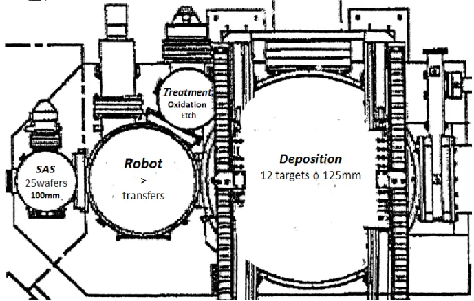
Our tool is an Actemium machine which possesses 12 targets that give us the opportunity to develop complex stacks involving a wide range of materials. Targets diameter is 125 mm which leads to a good homogeneity of the depositions on 100 mm wafers. This is also ensured by the rotation of the sample holder at 600°/s upon deposition. The whole deposition process is automated. Indeed, as shown in Figure I-10, our tool is equipped with a treatment chamber in which oxidation and etching
CHAPTER I: Introduction to the concepts and the experimental techniques
33
steps are taking place and a robot allows transferring the substrate from one chamber to the other as well as moving the substrate to place it in front of the chosen target. The deposited thicknesses are determined by the opening time of the shutter that covers the target. Deposition rates can be modulated by adjusting the current set point (typically between 60 and 350 mA), that is to say the power applied to the cathode. The Ar pressure in the chamber will also influence the deposition rate. In our system, it is set to 2.10-3 mbar. The rates are basically ranging between 0.03 nm/s and 0.2 nm/s, making it possible to deposit layers as thin as a few tenths of nanometer. In order to calibrate them properly, X-rays reflectivity is used. Regular calibrations are performed as aging of the targets will tend to reduce the deposition rates.
Figure I-10: Plan of the Actemium deposition tool showing the organization of the different chambers.
One interesting feature of our deposition machine is that we have the ability to create thickness gradients by shifting the substrate from the on-axis position. The two configurations are represented in Figure I-11. When the substrate is in the off-axis position and the sample holder is not rotated, a gradient of thickness appears in the deposited material. This wedge depends on the distance between the sample and the target. In the standard configuration, the distance amounts to 100 mm and allows a variation of about a factor 2 along the 100 mm wafer surface. The gradients are calibrated for each material, either by X-rays reflectivity or resistivity measurements.
34
Figure I-11: Schematic representation of the two possible geometries in our deposition tool.
As we said earlier, our deposition tool is equipped with a treatment chamber in which oxidation steps can be performed. This is one way to create the oxide barriers of the tunnel junctions. In our studies, we used mostly MgO barriers obtained by natural oxidation of metallic Mg. A thin layer of Mg is deposited in the sputtering chamber and is then exposed to an oxygen atmosphere for a given time in the treatment chamber. Two procedures are employed depending on the RA levels that are targeted. For low RA (typically 5-10 m2), a dynamic oxidation is performed at a low oxygen pressure of 3.10-2 mbar, with a 100 sccm flow, for 360 s. For higher RA (typically 25-50 m2), a static oxidation is used in which the sample is exposed to a high oxygen pressure of 150 mbar for 10s. The tool is also able to perform plasma oxidations that utilize an oxygen plasma to oxidize a metallic element. This technique is more commonly applied to alumina barriers. Besides, we also have the possibility to deposit the oxide directly from a ceramic MgO target. In that case, a radiofrequency power supply is needed. A current of alternative polarity is applied to the target, avoiding the accumulation of charges that would otherwise strongly decrease the deposition rate of the material.
CHAPTER I: Introduction to the concepts and the experimental techniques
35
I-5.
Characterisation techniques
I-5.1 Magnetic characterization
a) Vibrating Sample Magnetometry
Vibrating Sample Magnetometry is a tool used to characterize the magnetic properties of a sample. It allows measuring the variation of the magnetic moment as a function of applied field, thus enabling to plot its hysteresis loop. To do this, the sample is fixed to a sample holder located in the gap of an electromagnet. It is then translated vertically at a given frequency. This vibration induces a change of magnetic flux related to the magnetic moment of the sample that is transformed into a current in the detection coils. A schematic representation is given in Figure I-12.
Figure I-12: Working principle of a VSM.
The advantage of this technique is that it is rather accurate (around 10-5 emu) and that magnetic field can be applied along any direction of the sample by setting the measurement angle. This is a convenient and rapid way to evaluate the anisotropy of a sample as both easy and hard axis loops can be performed. With our tool, magnetic fields as high as 17 kOe may be reached. One should note that the sample holder adds a contribution to the measured signal. Most of the time, it can be easily removed as it varies linearly with field (diamagnetic or paramagnetic holder). However, in the case of a sample presenting a very large saturation field, the slope might be difficult to determine.
![Figure I-1: Hall resistance as a function of perpendicular applied field for (a) Pt3/CoFe0.6/AlOx samples naturally oxidized in air with varying thicknesses of Al [Mon-02] (b) Pt3/Co0.6/AlOx samples plasma oxidized with different oxidation t](https://thumb-eu.123doks.com/thumbv2/123doknet/12871150.369303/18.892.133.781.244.504/resistance-function-perpendicular-naturally-oxidized-thicknesses-different-oxidation.webp)
![Figure I-2: Example of a plot of K eff .t as a function of t for Co/Pd multilayers [Joh-96]](https://thumb-eu.123doks.com/thumbv2/123doknet/12871150.369303/20.892.273.647.101.381/figure-example-plot-eff-function-pd-multilayers-joh.webp)