HAL Id: tel-02370413
https://tel.archives-ouvertes.fr/tel-02370413
Submitted on 19 Nov 2019HAL is a multi-disciplinary open access archive for the deposit and dissemination of sci-entific research documents, whether they are pub-lished or not. The documents may come from teaching and research institutions in France or abroad, or from public or private research centers.
L’archive ouverte pluridisciplinaire HAL, est destinée au dépôt et à la diffusion de documents scientifiques de niveau recherche, publiés ou non, émanant des établissements d’enseignement et de recherche français ou étrangers, des laboratoires publics ou privés.
Étude des caloducs cryogéniques pulsés diphasiques d’un
mètre de longueur
Maria Asuncion Barba Higueras
To cite this version:
Maria Asuncion Barba Higueras. Étude des caloducs cryogéniques pulsés diphasiques d’un mètre de longueur. Thermics [physics.class-ph]. Université Paris-Saclay, 2019. English. �NNT : 2019SACLS224�. �tel-02370413�
Th
`ese
de
doctor
at
NNT
:2019SA
CLS224
Study of Meter-scale Horizontal
Cryogenic Pulsating Heat Pipes
Th`ese de doctorat de l’Universit´e Paris-Saclay pr´epar´ee `a l’Universit´e Paris-Sud Ecole doctorale n◦576 Particules, Hadrons, ´Energie, Noyau,
Instrumentation, Imagerie, Cosmos, et Simulation (PHENIICS)
Sp´ecialit´e de doctorat : Physique des acc´el´erateurs
Th`ese pr´esent´ee et soutenue `a Saclay, le 18 Septembre 2019, par
M
AR´
IAA
SUNCION´
B
ARBAH
IGUERASComposition du Jury :
F. Lusseyran
Docteur, Directeur de recherche, Laboratoire LIMSI Pr´esident M. Marengo
Professeur, University of Brighton Rapporteur F. Lef`evre
Professeur, INSA de Lyon Rapporteur M. Breschi
Professeur, Universit`a di Bologna Examinateur P. V´edrine
Docteur, CEA de Saclay Examinateur P. Br´edy
Docteur, CEA de Saclay Examinateur B. Baudouy
Docteur, Directeur de recherche, CEA de Saclay Directeur de th`ese R. Bruce
Remerciements
Cet ´ecrit est le r´esultat de trois ann´ees de travail de recherche r´ealis´ee au sein du Laboratoire de Cryog´enie et Stations d’Essais (LCSE) du D´epartement des Acc´el´erateurs, Cryog´enie et Magn´etisme (DACM) appartenant `a l’Institut de Recherche sur Lois Fondamentales de l’Univers (IRFU) du Commissariat `a l’´Energie Atomique et aux ´Energies Alternatives (CEA) de Paris - Saclay. Avant d’aborder cet ouvrage, je tiens `a remercier dans ces quelques lignes toutes les personnes qui m’ont accompagn´ees tout au long de ce travail de doctorat.
Je voudrais tout d’abord remercier la direction de l’IRFU qui a enti`erement financ´e mes travaux de th`ese. De mˆeme, je voudrais remercier la direction du DACM et du LCSE, Messieurs Pierre V´edrine, Philippe Br´edy, Christophe Mayri et Madame Roser Vallcorba, pour leur accueil et leur disponibilit´e de tous les instants ainsi que pour avoir financ´e ma participation aux diff´erentes formations et conf´erences qui m’ont permis d’approfondir mes connaissances et de m’int´egrer dans la communaut´e de la cryog´enie et la supraconductivit´e.
De plus, c’est un honneur pour moi d’avoir compt´e dans mon jury de th`ese des experts reconnus dans les domaines de la m´ecanique des fluides, des transferts thermiques et de la supraconductivit´e: M. Lusseyran, M. Marengo, M. Lef`evre, M. Breschi, M. V´edrine et M. Br´edy. Je les remercie ´enorm´ement pour l’int´erˆet qu’ils ont port´e pour mon sujet, pour leurs corrections, suggestions et conseils, qui ont contribu´e `a la qualit´e de l’´ecrit et `a un ´echange tr`es enrichissant lors de la soutenance.
Concernant les personnes qui ont travaill´e plus directement avec moi durant cette th`ese, je voudrais remercier tout d’abord mon directeur de th`ese, Bertrand Baudouy, pour son encadrement, son soutien, sa disponibilit´e constante, son savoir-faire scientifique, la rigueur de ses corrections et ses conseils (scientifiques et humains). Tout cela a ´et´e un pilier essentiel de la r´eussite de ce travail. De mˆeme, je remercie Romain Bruce, pour son soutien et dynamisme, pour avoir cru en mes capacit´es plus que moi-mˆeme, pour ses conseils qui m’ont guid´e vers les bons chemins dans l’analyse des ph´enom`enes physiques et le d´eveloppement des syst`emes num´eriques. Sa passion pour la science a ´et´e une v´eritable source de motivation pour l’aboutissement de mes recherches. Cela ´et´e un plaisir de continuer les travaux initi´es lors de son postdoctorat.
Un grand merci aussi `a Florent Bouchet, stagiaire avec lequel j’ai eu le plaisir de travailler pendant cette th`ese. Avec son travail et effort il a ´enorm´ement contribu´e `a la grande base de donn´ees exp´erimentales de cette th`ese, en plus d’ˆetre un excellent coll`egue et ami.
Je souhaiterais aussi remercier tr`es fortement tous les membres du laboratoire LCSE, avec une sp´eciale mention `a Cl´ement Hilaire, Antoine Bonelli, Gilles Authelet, Jean-Marc Gheller, Vadim Stepanov, Charles Mailleret, Antoine Caisson, Andrea Vitrano, Romain Boy, Denis Bouziat et les nombreuses personnes que j’ai crois´ees durant ces trois ann´ees. Je voudrais les remercier pour leurs conseils et leurs apprentissages qui ont ´et´e tr`es utiles pour la r´ealisation des exp´eriences et, surtout, pour les bons moments pass´es ensemble. Ils ont ´et´e des v´eritables rayons de soleil chaque jour!
Ajout´e `a cela, je tiens aussi `a remercier les membres du personnel administratif, S´everine Candau et Armelle Le Noa, l’ing´enieur de s´ecurit´e, Olivier Kuster et les ing´enieurs informatique
pour leur disponibilit´e et leur amabilit´e. Merci aussi `a tous les membres du laboratoire LEAS pour les conseils et discussions enrichissantes ainsi que les bons moments pass´es ensemble, avec une mention sp´eciale `a Fran¸cois-Paul Juster, les conseils des plus sages sont toujours les meilleurs. Pour finir, je tiens `a exprimer ma gratitude `a mes parents, mon fr`ere et le reste de ma famille et proches pour leur soutien incontournable durant tout mon doctorat, voire depuis toujours, ´etant un de mes piliers fondamentaux. Merci infiniment.
Contents
Contents i List of Figures v List of Tables xv Nomenclature xix Introduction 11 Cryogenic cooling for superconducting magnets 5
1.1 Scientific and technical background . . . 5
1.1.1 Cryogenics . . . 5
1.1.2 Superconductivity . . . 5
1.1.3 Magnet cooling techniques. . . 7
1.1.4 The need of developing new cryogenic technologies . . . 8
1.2 On the definition of Pulsating Heat Pipes . . . 9
1.3 Literature Review on Pulsating Heat Pipes . . . 12
1.3.1 Cryogenic Pulsating Heat Pipes . . . 12
1.3.2 Microgravity conditions and horizontal inclination . . . 15
1.3.3 Influence of the working fluid . . . 16
1.3.4 Fluid circulation in Pulsating Heat Pipes . . . 18
1.3.5 Working conditions in Pulsating Heat Pipes . . . 19
1.3.6 Geometric parameters . . . 21
1.3.7 Modelling of Pulsating Heat Pipes . . . 23
1.3.8 Applications . . . 25
1.4 The contribution of this work . . . 25
2 The experimental facility 29 2.1 The cryostat . . . 29
2.2 The pulsating heat pipes . . . 31
2.3 Instrumentation and configurations . . . 35
Contents ii
2.3.2 Pressure sensors . . . 37
2.3.3 Locations and characteristics of sensors . . . 39
2.3.4 Heaters . . . 39
2.3.5 Power supply systems . . . 41
2.4 Gas supply system . . . 42
2.5 Signal data acquisition . . . 42
2.6 Data Processing . . . 44
2.7 Preparation of experiments . . . 46
2.8 Start-Up procedure . . . 47
2.9 Final comments . . . 48
3 Generic working conditions 51 3.1 Previous work . . . 51
3.2 Reference test . . . 53
3.2.1 Experimental procedure . . . 53
3.2.2 General test description . . . 53
3.2.3 Evolution of the thermal performance . . . 56
3.2.4 Thermodynamics and fluid distribution . . . 56
3.2.5 Dry-out and limits . . . 66
3.3 Conclusions . . . 68
4 Comparison between different working fluids 69 4.1 Comparison with the reference test . . . 70
4.1.1 General experimental results . . . 70
4.1.2 Temperature distributions and fluid oscillations . . . 73
4.1.3 Evolution of thermal performances . . . 75
4.2 The influence of the buffer volume . . . 77
4.3 Differences in fluids’ behavior . . . 81
4.4 Long stability tests . . . 86
4.5 Conclusions . . . 87
5 Specific working conditions and limitations 89 5.1 Influence of the start-up conditions . . . 89
5.2 Influence of the temperature of the condenser . . . 94
5.3 Effect of the number of turns . . . 99
5.4 Quench tests for magnet applications . . . 106
5.5 Conclusions . . . 113
6 Numerical simulation of the fluid’s behavior in a capillary tube 115 6.1 Introduction. . . 115
Contents iii 6.3 Simulation models . . . 118 6.3.1 Dynamic model . . . 121 6.3.2 Thermal model . . . 124 6.4 Results. . . 130 6.4.1 Dynamic model . . . 130 6.4.2 Thermal model . . . 133 6.5 Conclusions . . . 135
Synthesis and comments 137 Conclusions and perspectives 141 A Calibration of Pt100 temperature sensors below 60 K 145 B Calibration of Kulite Pressure sensors 147 C Thermal response simulation 149 D Extrapolation of the thermal simulation to the other working fluids 153 E Power spectrums of temperature oscillations 155 F Fluid properties 157 G Neon’s critical diameter 163 H Example of experimental results at different start-up conditions 165 I Complementary experimental results of quench tests 171 J Complementary information of the simulation work 175 K R´esum´e en fran¸cais: ´Etude des caloducs cryog´eniques puls´es diphasiques d’un m`etre de longueur 179 K.1 Introduction . . . 179
K.2 Descriptif exp´erimental. . . 181
K.3 Analyse des r´esultats exp´erimentaux `a l’azote . . . 182
K.4 Comparaison des r´esultats exp´erimentaux avec diff´erents fluides de travail . 183 K.5 Comportements sp´ecifiques et limites du syst`eme PHP . . . 185
K.6 Simulation num´erique du comportement du fluide dans un tube capillaire . 186 K.7 Conclusions et Perspectives . . . 186
Contents iv
Bibliography 189
Abstract en fran¸cais 201
List of Figures
1.1 Critical surface of a superconductor. . . 6
1.2 Critical characteristics of some superconductors. Courtesy of P. Lee (NHMFL) 7 1.3 Range of working temperatures of cryogenic cooling fluids and critical tem-peratures of some superconductors. . . 8
1.4 Example of various cooling methods. . . 9
1.5 Schematic of the structure of a PHP. . . 10
1.6 Configurations of pulsating heat pipes. a) Closed-loop configuration b) Open-loop configuration. . . 11
1.7 Flow patterns observed in closed-loop pulsating heat pipes. . . 19
1.8 Thermodynamics of a PHP. . . 20
1.9 Results of cylindrical air bubbles rising in vertical tubes. Froude number versus E¨otv¨os number. . . 22
1.10 Alternating cooling and heating parts in the 1D thermal model. . . 23
2.1 Schematic illustration of the cryostat. . . 30
2.2 Thermal schematic of the experiment and picture of the interior view of the cryostat. . . 30
2.3 Aluminum structures inside the cryostat.. . . 31
2.4 Schematic illustration of the experimental facility. . . 32
2.5 Schematic illustration of a condenser part with its PHP inlet. . . 32
2.6 Machined copper plate. . . 33
2.7 Evaporator part of the PHP having 12 parallel tubes. . . 33
2.8 Schematic illustration of the copper thermal link and the thermalized inlet tube of a single PHP with the corresponding temperature sensors. . . 34
2.9 Schematic illustration of the copper sleeves. . . 34
2.10 Pt100 temperature sensor. . . 36
2.11 Sensitivity of Pt100 temperature sensor. . . 36
2.12 Cernox⃝R SD temperature sensor. . . . 37
2.13 Sensitivity of Cernox⃝R SD temperature sensor. . . . 37
2.14 Kulite⃝R Pressure Transducer. . . . 38
List of Figures vi
2.16 Locations of sensors in the three pulsating heat pipes. . . 40
2.17 Gas supply system. . . 43
2.18 Screenshot of the Lavbiew visualization program. . . 45
2.19 Simplified structure of the data processing code. . . 46
2.20 Schematic illustration of the gas supply circuit connected to the PHP with 36 turns with the corresponding lengths and diameters. . . 49
3.1 Schematic illustration of the 3.6 m long experimental facility. . . 51
3.2 Evolution of the PHP global pressure, the average temperature of the evap-orator and the condenser and the temperatures of the adiabatic part of a test with a fixed heat load in the 3.6 m long PHP version. . . 52
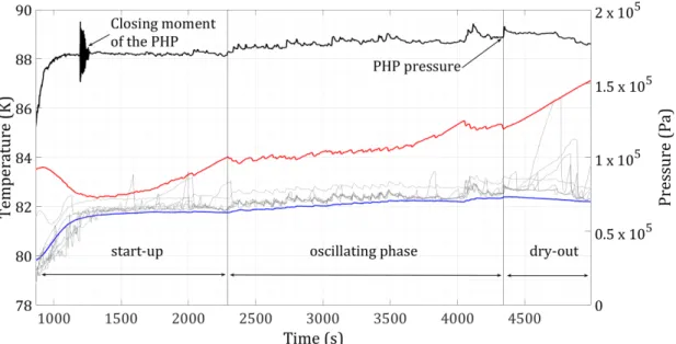
3.3 Evolution of the PHP global pressure, the average temperature of the evap-orator and the condenser and the temperatures of the adiabatic part of the reference test. . . 54
3.4 Evolution of the equivalent thermal conductivity. . . 57
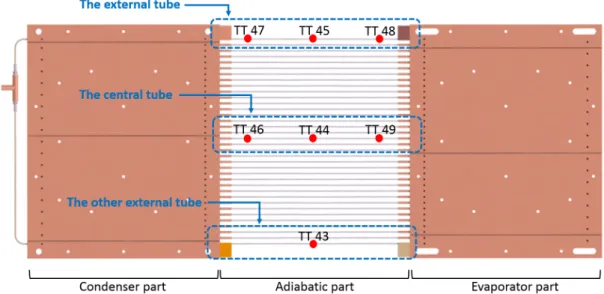
3.5 Locations of temperature and pressure sensors of the 36-turns PHP. . . 57
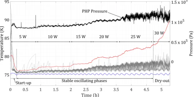
3.6 Evolution of the PHP pressure, the saturation temperature, the average temperatures of the evaporator and the condenser and the temperatures of the adiabatic part of the reference test.. . . 58
3.7 Evolution of the temperatures of the fluid inside the capillary tube located in the center of the PHP (sensors TT46, TT44 and TT49) and the saturation temperature at 5 and 10 W of input power respectively. . . 60
3.8 Evolution of the temperatures of the fluid inside the capillary tube located in the center of the PHP (sensors TT46, TT44 and TT49) and the saturation temperature at 15 W of input power. . . 61
3.9 Evolution of the temperatures of the fluid inside the capillary tube located in the center of the PHP (sensors TT46, TT44 and TT49) and the saturation temperature at 20 and 25 W of input power respectively.. . . 62
3.10 Evolution of the temperatures of the fluid inside the capillary tube located in the center of the PHP (sensors TT46, TT44 and TT49) and the saturation temperature at 30 W of input power. . . 62
3.11 Locations of the three monitored tubes of the adiabatic part. . . 63
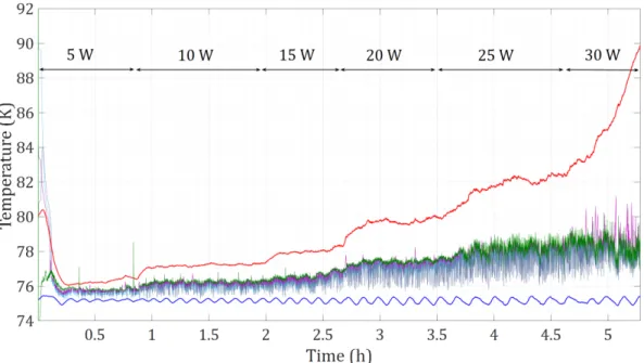
3.12 Evolution of the average temperature of the evaporator and the condenser, the saturation temperature and the temperatures of the adiabatic part (sen-sors TT45, TT47 and TT48) of the external tube. . . 63
3.13 Evolution of the average temperature of the evaporator and the condenser, the saturation temperature and the temperatures of the adiabatic part (sen-sors TT45, TT47 and TT48) of the central tube. . . 64
List of Figures vii
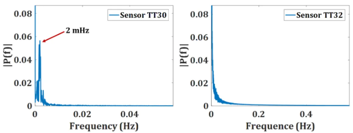
3.14 Evolution of the average temperature of the evaporator and the condenser, the saturation temperature and the temperatures of the adiabatic part (sen-sors TT45, TT47 and TT48) of the other external tube. . . 64 3.15 Power spectrum of temperature oscillations on sensors TT30 (condenser)
and TT32 (evaporator) during the entire reference test. . . 66 3.16 Power spectrum of temperature oscillations on sensor TT43 at different
power steps. . . 66 3.17 Power spectrum of temperature oscillations on sensor TT44 at different
power steps. . . 67 3.18 Power spectrum of temperature oscillations on sensor TT46 at different
power steps. . . 67
4.1 Evolution of the PHP pressure, the saturation temperature, the average temperatures of the evaporator and the condenser and the temperatures of the adiabatic part of a progressive heat load experiment using neon as working fluid. . . 71 4.2 Evolution of the PHP pressure, the saturation temperature, the average
temperatures of the evaporator and the condenser and the temperatures of the adiabatic part of a progressive heat load experiment using argon as working fluid. . . 73 4.3 Evolution of the temperatures of the fluid inside the capillary tube located in
the center of the PHP (sensors TT46, TT44 and TT49) and the saturation temperature at 20 and 45 W of input power respectively.. . . 74 4.4 Evolution of the temperatures of the fluid inside the capillary tube located in
the center of the PHP (sensors TT46, TT44 and TT49) and the saturation temperature at 15 and 30 W of input power respectively.. . . 75 4.5 Evolution of the temperatures of the fluid inside the capillary tube located in
the center of the PHP (sensors TT46, TT44 and TT49) and the saturation temperature during the dry-out phase (at 35 and 40 W of input power). . . 76 4.6 Evolution of the equivalent thermal conductivity of the same type of test
using different cryogenic fluids: nitrogen (referent test), neon and argon. . . 76 4.7 Evolution of the equivalent thermal conductivity and liquid filling ratio of
progressive heat load tests in the open configuration using neon as working fluid at different initial filling ratios in the open configuration. . . 78 4.8 Evolution of the equivalent thermal conductivity and liquid filling ratio of
progressive heat load tests in the closed configuration using neon as working fluid at different initial filling ratios. . . 79 4.9 Evolution of the equivalent thermal conductivity and liquid filling ratio of
progressive heat load tests in the open configuration using argon as working fluid at different initial filling ratios in the open configuration. . . 80
List of Figures viii
4.10 Evolution of the equivalent thermal conductivity and liquid filling ratio of progressive heat load tests in the closed configuration using argon as working fluid at different initial filling ratios. . . 81
4.11 Evolution of the equivalent thermal conductivity and liquid filling ratio of progressive heat load tests in the open configuration using nitrogen as working fluid at different initial filling ratios in the open configuration. . . . 82
4.12 Evolution of the equivalent thermal conductivity and liquid filling ratio of progressive heat load tests in the closed configuration using nitrogen as working fluid at different initial filling ratios. . . 83
4.13 Evolution of the PHP pressure, the saturation temperature, the average temperatures of the evaporator and the condenser and the temperatures of the adiabatic part of a progressive heat load experiment in closed configura-tion using nitrogen as working fluid with a filling ratio Rsat of 66.5% (80%
initially). Evolution of the PHP pressure, the saturation temperature, the average temperatures of the evaporator and the condenser and the temper-atures of the adiabatic part of a progressive heat load experiment in closed configuration using argon as working fluid with a filling ratio Rsat of 43.8%
(60% initially). . . 84
4.14 Evolution of the PHP pressure, the saturation temperature, the average temperatures of the evaporator and the condenser and the temperatures of the adiabatic part of fixed heat load experiments in closed configuration using nitrogen, neon and argon as working fluids respectively. . . 88
5.1 Evolution of the PHP pressure, the average temperatures of the evapo-rator and the condenser and the temperatures of the adiabatic part of a progressive heat load experiment in closed configuration using nitrogen as working fluid starting with the same temperature in the evaporator and the condenser after the filling process. . . 90
5.2 Evolution of the PHP pressure, the average temperatures of the evaporator and the condenser and the temperatures of the adiabatic part of a start-up test in closed configuration using nitrogen as working fluid with different initial temperature difference between the evaporator and the condenser: 5 K and 20 K respectively. . . 91
5.3 Evolution of the PHP pressure, the average temperatures of the evaporator and the condenser and the temperatures of the adiabatic part of a start-up test in closed configuration using nitrogen as working fluid (initial filling ratio of 50 %) with different initial heat loads during the filling process. . . 93
List of Figures ix
5.4 Evolution of the PHP pressure, the saturation temperature, the average temperatures of the evaporator and the condenser and the temperatures of the adiabatic part of a fixed heat load experiment in open configuration using nitrogen as working fluid in the PHP with 24 turns. . . 101 5.5 Evolution of the PHP pressure, the saturation temperature, the average
temperatures of the evaporator and the condenser and the temperatures of the adiabatic part of a fixed heat load experiment in open configuration using neon as working fluid in the PHP with 24 turns. . . 103 5.6 Evolution of the PHP pressure, the saturation temperature, the average
temperatures of the evaporator and the condenser and the temperatures of the adiabatic part of a fixed heat load experiment in open configuration using nitrogen as working fluid in the PHP with 12 turns. . . 104 5.7 Evolution of the PHP pressure, the saturation temperature, the average
temperatures of the evaporator and the condenser and the temperatures of the adiabatic part of a fixed heat load experiment in open configuration using neon as working fluid in the PHP with 12 turns. . . 105 5.8 Evolution of the temperature difference between the evaporator and the
condenser during quench tests of an equivalent energy of 10 kJ at different input powers and an initial filling ratio of 50 % using nitrogen and neon as working fluids, respectively. . . 108 5.9 Evolution of the temperature difference between the evaporator and the
condenser during quench tests using nitrogen as working fluid with an initial ratio of 50 % at different energies: 10 kJ, 50 kJ and 100 kJ, respectively. . . 110 5.10 Evolution of the temperature difference between the evaporator and the
condenser during quench tests using neon as working fluid with an initial ratio of 30 % at different energies: 10 kJ, 50 kJ and 100 kJ, respectively. . . 111 5.11 Evolution of the temperature difference between the evaporator and the
condenser during quench tests at an energy of 10 kJ using neon as working fluid with different initial filling ratios: 30 %, 50 % and 70 %, respectively. . 112
6.1 Schematic illustration of the experimental set-up of the reference case. . . . 117 6.2 Experimental results of the reference case. Tsat corresponds to the
calcu-lated saturation temperature, TµT C represents the measured temperature
in the evaporator part, TE corresponds to the temperature of the
evapora-tor copper plate and TC corresponds to the temperature of the condenser
copper plate. . . 118 6.3 Evolution of the imposed oscillations of the piston in the simulation of the
reference case (x=0 at the blind tube end). . . 119 6.4 Schematic illustration of a fluid interface with the volume fractions. . . 119
List of Figures x
6.5 Image zoom of the mesh for the dynamic model (the mesh dimensions are
identical in the entire figure). . . 122
6.6 Schematic illustration of the dynamic model with the geometry dimensions. 122 6.7 Initial and boundary conditions of the dynamic model. . . 123
6.8 Evolution of the saturation pressure and saturation temperature from the experimental reference case. . . 124
6.9 Schematic illustration of the equilibrium between surface tension forces in the triple line. . . 124
6.10 Image zoom of the mesh for the thermal model. . . 126
6.11 Schematic illustration of the thermal model. . . 126
6.12 Initial and boundary conditions of the thermal model. . . 127
6.13 Initial and boundary conditions of the second configuration of the thermal model. . . 128
6.14 Evolution of the fluid-vapor interface as a function of the contact angle. . . 131
6.15 Numerical results of the dynamic flow simulation with a fixed contact angle of 30o. . . . 132
6.16 Temperature evolution during the thermal simulation with a fixed pressure at the condenser end.. . . 133
6.17 Zoom of the capillary tube of an instant of the second thermal simulation. . 134
6.18 Temperature evolution during the thermal simulation with a variable mass flow at the condenser end. . . 135
C.1 Schematic illustration of the adiabatic tubing part of the Comsol Multiphysics⃝R thermal simulation. . . 149
C.2 Imposed temperature increase to the liquid nitrogen in contact with the inner surface of the capillary tube, and temperature response at the inner surface of the tube and at one of the sensors (all the sensors show exactly the same tendency). . . 151
E.1 Power spectrum evolution of temperature oscillations on sensor TT45 dur-ing a progressive heat load test usdur-ing neon as workdur-ing fluid. . . 155
E.2 Power spectrum evolution of temperature oscillations on sensor TT30 dur-ing stable phases of a progressive heat load test usdur-ing argon as workdur-ing fluid. . . 156
F.1 Evolution of the surface tension during progressive heat load tests of the three working fluids: nitrogen, neon and argon. . . 157
List of Figures xi
F.2 Evolution of the dynamic viscosity of the liquid phase during progressive heat load tests of the three working fluids: nitrogen at saturation temper-ature, nitrogen at condenser’s tempertemper-ature, neon at saturation conditions, neon at condenser’s temperature, argon at saturation conditions and argon at condenser’s temperature. . . 158
F.3 Average values of the specific heat of the liquid parts during progressive heat load tests of the three working fluids: nitrogen, neon and argon. The specific heat is calculated considering the liquid parts at saturation temperature and at the temperature of the condenser. . . 158
F.4 Average values of the liquid density during progressive heat load tests of the three working fluids: nitrogen, neon and argon. The liquid density is calculated at saturation temperature and at the temperature of the condenser.159
F.5 Evolution of the product ρl× Cpl during progressive heat load tests of the
three working fluids: nitrogen at saturation temperature, nitrogen at con-denser’s temperature, neon at saturation conditions, neon at concon-denser’s temperature, argon at saturation conditions and argon at condenser’s tem-perature. . . 159 F.6 Evolution of the liquid thermal conductivity during progressive heat load
tests of the three working fluids: nitrogen at saturation temperature, ni-trogen at condenser’s temperature, neon at saturation conditions, neon at condenser’s temperature, argon at saturation conditions and argon at con-denser’s temperature. . . 160 F.7 Evolution of the latent heat during progressive heat load tests of the three
working fluids: nitrogen, neon and argon. . . 160 F.8 Evolution of the Jacob number during progressive heat load tests of the
three working fluids: nitrogen, neon and argon. . . 161 F.9 Evolution of the temperature difference between the evaporator and the
condenser during progressive heat load tests of the three working fluids: nitrogen, neon and argon. . . 161
F.10 Evolution of the rate dp/dT at saturation conditions during progressive heat load tests of the three working fluids: nitrogen, neon and argon.. . . 162
G.1 Evolution of the density difference between the liquid and the vapor phase during a progressive heat load test with neon as working fluid. . . 163
G.2 Evolution of the surface tension during a progressive heat load test with neon as working fluid. . . 164
G.3 Evolution of the critical diameter during a progressive heat load test with neon as working fluid. . . 164
List of Figures xii
H.1 Evolution of the PHP pressure, the average temperatures of the evaporator and the condenser and the temperatures of the adiabatic part of a start-up test in closed configuration using nitrogen as working fluid (initial filling ratio of 30 %) with different initial heat loads during the filling process in the PHP with 36 turns. . . 166
H.2 Evolution of the PHP pressure, the average temperatures of the evaporator and the condenser and the temperatures of the adiabatic part of a start-up test in closed configuration using nitrogen as working fluid (initial filling ratio of 70 %) with different initial heat loads during the filling process in the PHP with 36 turns. The fluid stop phenomena are identified by a red ellipse. . . 167
H.3 Evolution of the PHP pressure, the average temperatures of the evaporator and the condenser and the temperatures of the adiabatic part of a start-up test in closed configuration using neon as working fluid (initial filling ratio of 30 %) with different initial heat loads during the filling process in the PHP with 36 turns.. . . 168
H.4 Evolution of the PHP pressure, the average temperatures of the evaporator and the condenser and the temperatures of the adiabatic part of a start-up test in closed configuration using neon as working fluid (initial filling ratio of 50 %) with different initial heat loads during the filling process in the PHP with 36 turns.. . . 169
H.5 Evolution of the PHP pressure, the average temperatures of the evaporator and the condenser and the temperatures of the adiabatic part of a start-up test in closed configuration using neon as working fluid (initial filling ratio of 70 %) with different initial heat loads during the filling process in the PHP with 36 turns.. . . 170
I.1 Evolution of the specific heat of copper (RRR=50) with temperature. Ranges of working temperatures of the PHP using neon and nitrogen as working fluids are indicated.. . . 171
I.2 Evolution of the PHP pressure, the average temperatures of the evaporator and the condenser and the temperatures of the adiabatic part of several quench tests of 10 kJ using nitrogen as working fluid (initial filling ratio of 50 %). . . 172
I.3 Evolution of the PHP pressure, the average temperatures of the evaporator and the condenser and the temperatures of the adiabatic part of several quench tests of 50 kJ using nitrogen as working fluid (initial filling ratio of 50 %). . . 172
List of Figures xiii
I.4 Evolution of the PHP pressure, the average temperatures of the evaporator and the condenser and the temperatures of the adiabatic part of several quench tests of 100 kJ using nitrogen as working fluid (initial filling ratio
of 50 %).. . . 173
I.5 Evolution of the PHP pressure, the average temperatures of the evaporator and the condenser and the temperatures of the adiabatic part of several quench tests of 10 kJ using neon as working fluid (initial filling ratio of 30 %).173 I.6 Evolution of the PHP pressure, the average temperatures of the evaporator and the condenser and the temperatures of the adiabatic part of several quench tests of 50 kJ using neon as working fluid (initial filling ratio of 30 %).174 I.7 Evolution of the PHP pressure, the average temperatures of the evaporator and the condenser and the temperatures of the adiabatic part of several quench tests of 100 kJ using neon as working fluid (initial filling ratio of 30 %). . . 174
J.1 Second mesh tested with the dynamic model. . . 176
J.2 Image zoom of the second mesh tested with the dynamic model. . . 176
J.3 Second mesh tested with the thermal model. . . 176
J.4 Image zoom of the second mesh tested with the thermal model. . . 177
J.5 Detailed image zoom of the second mesh tested with the thermal model. . . 177
List of Tables
2.1 Specific characteristics of sensors. . . 39
2.2 Specific characteristics of heaters. . . 41
4.1 Ranges of working temperatures. . . 69
4.2 Maximum inner diameters. . . 71
5.1 Start-up variables for nitrogen. . . 91
5.2 Start-up variables for neon. . . 94
5.3 Tests in open configuration using nitrogen as working fluid at 20% of initial filling ratio. . . 95
5.4 Tests in open configuration using nitrogen as working fluid at 50% of initial filling ratio. . . 95
5.5 Tests in open configuration using nitrogen as working fluid at 80% of initial filling ratio. . . 95
5.6 Tests in closed configuration using nitrogen as working fluid at 20% of initial filling ratio. . . 96
5.7 Tests in closed configuration using nitrogen as working fluid at 50% of initial filling ratio. . . 97
5.8 Tests in closed configuration using neon as working fluid at 30% of initial filling ratio. . . 98
5.9 Tests in closed configuration using neon as working fluid at 50% of initial filling ratio. . . 98
5.10 Tests in closed configuration using neon as working fluid at 80% of initial filling ratio. . . 98
5.11 Tests in open configuration in the PHP with 24 turns using nitrogen as working fluid at 50% of initial filling ratio. . . 102
5.12 Tests in open configuration in the PHP with 24 turns using neon as working fluid at 50% of initial filling ratio.. . . 103
5.13 Tests in open configuration in the PHP with 12 turns using neon as working fluid at 50% of initial filling ratio.. . . 105
List of Tables xvi
5.15 List of quench tests with neon. . . 107
6.1 Properties of the solid and fluid phases of the thermal model (from Cry-oComp database [1] and Refprop database [2]). . . 129 6.2 Average thicknesses of the liquid films. . . 130
Nomenclature
Roman letters
˙
mlv rate of mass transfer during the evaporation process kg/(m3.s)
˙
mvl rate of mass transfer during the condensation process kg/(m3.s)
Bc critical magnetic field T
Cp specific heat kJ/(kg.K)
E energy J
F external force (kg.m)/s2
J c critical current density A/m2
Lv latent heat kJ/kg
M molar mass kg/mol
P pressure P a p pressure P a R radius m R resistance Ω S source term T temperature K T c critical temperature K
Uf volume flux through the face m3/s
V volume m3
v velocity m/s
Greek letters
α volume fraction ϵ emissivity
Nomenclature xviii
λ thermal conductivity W/(m.K)
ρ density kg/m3
µ dynamic viscosity P a.s
σ surface tension N/m
σb Boltzmann constant W/(m2.K4)
Dimensionless numbers
Cou Courant number; Cou = v∆t∆x Eo¨ E¨otv¨os number; E ¨o= D2g(ρ
l− ρv)/σ F r Froude number; F r = V µl gD2ρ l J a Jacob number; Ja = Cp·∆TLv P s Poiseuille number; P s = V2 gD
Subscripts and superscripts
0 related to resistance at 0◦C
1 related to phase one 2 related to phase two
ec related to evaporator and condenser temperatures l related to liquid phase
lg related to liquid-gas interface p related to one fluid phase
php related to the volume of the PHP q related to one fluid phase
RT D related to platinum resistance thermometers sat related to saturation conditions
sg related to solid-gas interface sl related to solid-liquid interface v related to vapor phase
Physical constants
Nomenclature xix
R gas constant 8.314472J/(mol.K)
Acronyms
APT Absolute Pressure Transducer BV Buffer Volume
CFD Computational Fluid Dynamics FFT Fast Fourier Transform
FR Filling Ratio %
MLI Multi-Layer Insulation
NHMFL National High Magnetic Field Laboratory NTC Negative Temperature Coefficient
CEA Atomic Energy Commission
DACM Accelerators, Cryogenics and Magnetism Department HTS High Temperature Superconductors
MRI Magnetic Resonance Imaging PHP Pulsating Heat Pipe
PHPs Pulsating Heat Pipes
PTC Positive Temperature Coefficient
SR2S Space Radiation Superconductive Shield VOF Volume of Fluid
UDF User-Defined Function VP Vacuum Pump
Introduction
Cryogenics is the area of physics covering the production of low temperature environment and study of physical effects at these temperatures. Its use cover a wide range of appli-cations in electronics, medicine, physics, rocketry, levitation and high magnetic field pro-duction. It is indispensable for revealing in certain materials their superconducting state, only attainable at cryogenic temperatures. In fact, below a certain critical temperature (Tc), the superconductivity phenomenon appears in materials (known as superconductors),
allowing the circulation of electrical current without any resistance or energy loss. Con-sequently, in the case of superconducting magnets, this lack of electrical resistance allows the generation of huge magnetic fields used, for example, in Magnetic Resonance Imaging (MRI) for medical applications or to deviate and focalize particles in accelerators.
Nowadays, research efforts on superconductivity focus on developing new materi-als with high critical temperature, known as High Temperature Superconductors (HTS), avoiding the use of helium as cryogenic cooling fluids. This allows to deal with repetitive helium scarcities by using other cryogenic fluids more affordable existing in large quantities on earth.
In addition, the interest in superconducting technologies for space applications is demanding new cryogenic technologies able to work without gravity, as studied in the project Space Radiation Superconductive Shield (SR2S) [3,4]. Funded by the European Commission, the objective of this scientific project was to develop technologies to protect the astronauts during deep space travel missions from overexposure to harmful radiation, which increases the probability of developing serious diseases, such as cancer. During this project, active shielding solutions have been studied involving superconducting magnets surrounding the space shuttles and using the magnetic field to deflect particles by chang-ing their trajectory as the geomagnetic field does on earth. The project succeeded in demonstrating the potential of key technologies needed for the development of such an active magnetic shield. As a member of this project, the Accelerators, Cryogenics and Magnetism Department (DACM) of the CEA Paris - Saclay, worked on the cryogenic cooling technology for this superconducting space magnet. The DACM developed meter-scale cryogenic Pulsating Heat Pipes (PHPs), one of the longest created so far, as a novel technology for space applications.
Introduction 2
Invented by Akachi in the 90’s, pulsating heat pipes have been widely studied at room temperature by Khandekar [5], for example, and developed in multiple sizes for different applications, such as electronics cooling [6] or thermal storage [7,8]. In the cryogenic field, pulsating heat pipes have been mostly studied for cooling superconducting magnets. For example, a PHP of a few centimeters long has been tested by Mito et Natsume [9–12] using different cryogenic working fluids. At the same time, in the meter-scale, a 1 m long vertical cryogenic PHP has been studied by Fonseca [13] using helium as working fluid. The literature reveals that pulsating heat pipes working in no-gravity conditions are comparable to the ones working in horizontal position on earth [14]. However, no horizontal meter-scale cryogenic PHP able to work with different fluids has been developed until now. Concerning numerical simulations related to the physical phenomena occurring in pulsating heat pipes, the main numerical codes have been developed in one dimension by Shafii et Zhang [15, 16] and later by Mameli et al. [17] and Nikolayev et al. [18– 20]. Nowadays, there is no effective method to predict PHPs behavior and a completed numerical model of a PHP would be a step towards a predictive tool for future PHPs designs. The development of 2D numerical models would represent the first step for a future simulation of an entire PHP. To summarize, the chaotic behavior of the pulsating heat pipes makes them unpredictable and a more fundamental comprehension, guided by experimental and numerical tests, is needed for the development of future cryogenic pulsating heat pipes design applications.
For these reasons, the objective of the present work consists in characterizing the thermohydraulic behavior of the meter-scale horizontal cryogenic PHPs as a cooling solu-tion for superconducting magnets.
In chapter 1 the role of cryogenics and the superconductivity phenomenon are de-fined. The main existing superconducting magnet cooling techniques are exposed and a detailed definition followed by a literature review on pulsating heat pipes is given. Finally, the motivation and contribution of this work are provided.
Chapter 2 is dedicated to the description of the cryogenic experimental facility, composed of three horizontal one-meter long pulsating heat pipes.
The following chapters focus on the experimental and numerical results collected during the present research project. In chapter 3, experimental results obtained using nitrogen as working fluid during a progressive heat load test are presented. The thermo-dynamic characteristics of the fluid are defined based on the temperature and pressure evolution of the evaporator, adiabatic and condenser parts. Thermal performance and circulation modes are also provided. This test will be considered as the “reference” to compare with other experimental results in the following chapters.
Chapter4is dedicated to a comparison of the experimental results from progressive heat load and fixed heat load tests using three different working fluids, which are nitrogen,
Introduction 3
neon and argon. Physical parameters of the different working fluid are compared to un-derstand differences in the fluid’s behavior. Moreover, the influence of the buffer volume connection to the PHP during experimental tests is analyzed.
Specific tests to determine the influence in the thermal performance of the start-up conditions and the temperature of the condenser have also been performed. These experimental results are presented in chapter5. This chapter also focuses on the influence of the number of turns in the thermal performance of the system. Finally, results of tests of a sudden increase of heat load are discussed. These tests are supposed to simulate the heat load submitted during the quench of a superconducting magnet to help comprehend the transient behavior of such heat pipes.
Chapter 6is dedicated to the numerical work developed during the present research project. Firstly, the experimental reference model of a single-branch cryogenic PHP is defined. Secondly, the 2D axisymmetric numerical model with assumptions and limiting conditions is presented. Then, the numerical results are shown and explained with respect to the literature findings.
Finally, the last part of this document reviews the findings of this work and identifies potential investigations to solve new questions concerning the operating mode of pulsating heat pipes.
Chapter 1
Cryogenic cooling for
superconducting magnets
1.1
Scientific and technical background
1.1.1 Cryogenics
Cryogenics is the area of physics related to the phenomena and processes at low tempera-tures, usually defined as below 120 K [21]. The specific phenomena that occur at cryogenic temperatures refers to the characteristics of fluids and materials such as liquefaction and solidification of ambient gases, ductility of structural materials, heat transfer capacities of fluids and materials, or even the appearance of quantum effects like superconductivity and superfluidity.
In this context, numerous cryogenic technologies have been developed for a huge range of applications, from cryopreservation systems in biology conservation to cryogenics fuels as propellants for space rockets (liquid hydrogen is the most common example) or cooling of superconductors (including magnets, wires and electronic components).
The present research work focuses on the cryogenic technology allowing the appear-ance of the superconductivity phenomena in superconducting magnets.
1.1.2 Superconductivity
Discovered by H. Kamerlingh Onnes in 1911, the superconductivity is the physical phe-nomenon corresponding to zero electrical resistance. A superconductor is a material able to conduct electrical current without resistance and, consequently, any heat dissipation by Joule effect. It is actually the prerequisite for most applications, such as high-current transmission lines or high-field magnets, reducing dramatically operation costs [22].
Nev-Chapter 1. Cryogenic solutions to cool superconducting magnets 6 B(T ) T(K) Jc(A/m−2) sup ercond ucting state normalstate Bc Tc Jc
Figure 1.1: Critical surface of a superconductor.
ertheless, this superconducting state is reached only below a certain temperature (in the cryogenic range), called critical temperature (Tc), achieved using cryogenic cooling tech-niques.
This temperature requirement can be reduced in the presence of magnetic field (B) and/or electrical current density (J) in the bulk of the material. As a result, a “super-conducting region” can be represented graphically relating the critical current density, the critical magnetic field and the critical temperature (Jc, Bc and Tc respectively) in what is known as the critical surface, shown in Fig. 1.1. Out of this region, the material is not in superconducting state. Consequently, if one of the three parameters is increased, the superconducting region on the plane defined by the other two is necessarily reduced. Thus, fixing one parameter, the evolution of the other two parameters can be represented in what is known as the critical curve. As an example, critical curves at fixed temperature of some superconductors are presented in Fig. 1.2.
High magnetic fields can be generated by superconducting magnets by using signif-icantly high current densities. Considering the characteristics described previously, the working temperature (T ) will be reduced from the maximum critical temperature (Tc) of the superconductor material (T < Tc at B = 0 and J = 0). Due to this, the choice of a appropriate cooling system with its cryogenic working fluid is crucial to maintain the superconductor in its superconducting state and therefore generate the desired
mag-Chapter 1. Cryogenic solutions to cool superconducting magnets 7
Figure 1.2: Critical characteristics of some superconductors. Courtesy of P. Lee (NHMFL)
netic field. It can be seen in Fig. 1.3, the range of working temperatures of the available cryogenic fluids and the critical temperatures of some superconductors. For example of the most used superconductors, the NbTi, has a critical temperature of 9 K. It has been always associated with helium which practical temperature range is around 1.8 to 4.2 K. This is to have a sufficient temperature margin to ensure stable working conditions.
In this section, a simplified definition of the superconductivity is given to under-stand the relation in the present research project between superconducting magnets and cryogenics. Nevertheless, it is important to mention that superconductivity is also char-acterized by another phenomena which is the expulsion of the magnetic field from the material (known as the Meissner effect), and that there are other factors which can af-fect the superconducting state, such as the microstructures, which alter magnetic vortex dynamics [22].
1.1.3 Magnet cooling techniques
There exist two main categories for cooling superconducting magnets: the “direct method” and the “indirect method”. The first one uses a cryogenic fluid in direct contact with the superconductor, the magnets is then considered as a “wet” magnet. The second method uses a cryogenic fluid or a cooling system through intermediate thermal components. In this case, the magnet is considered as a “dry” magnet. Both cooling methods can be
Chapter 1. Cryogenic solutions to cool superconducting magnets 8
Figure 1.3: Range of working temperatures of cryogenic cooling fluids and critical tem-peratures of some superconductors.
used through different configurations, as can be seen in Fig. 1.4 and can be divided into subcategories depending on the physical phenomena employed to cool, such as pool boiling convection (cooling baths), forced convection, natural circulation and pure solid conduction.
The choice of the cooling system mainly depends on the superconductor type (and its critical temperature), the geometric configurations, the heat load to evacuate and its time distribution. Consequently, the working fluid or materials will be selected to meet the demands.
Each method has its own advantages, the “direct” cooling method ensures a perfect contact between the cryogenic fluid and the magnet, giving a large heat transfer rate and an enthalpy reserve. The “indirect” method consumes considerably less cryogenic fluid, and offers a larger number of possible configurations, often combining a copper thermal link connected to a heat exchanger using a cryogenic fluid and linked to a cryocooler. Pulsating heat pipes are an example of thermal links that can be used in this indirect method and will be defined below in section1.2.
1.1.4 The need of developing new cryogenic technologies
Nowadays, helium prices are unstable and subject to scarcities around the globe. At the beginning of the 20th century, the US Federal Reserve ensured stable helium supply offering low prices. After several crisis and the privatization of the organization, helium production these days is provided by a small group of countries, such as Algeria, Russia, Poland, Qatar and also the US [24]. Political instability, technical problems and the desire of certain countries to fill their reserves have generated a market crisis increasing the prices.
The development of low consumption cooling technologies using other cryogenic fluids seems to be a solution to avoid helium price dependence. Since other cryogenic fluids liquefy at higher temperatures than helium, in the case of superconducting magnets, the mentioned new technologies could be used to cool superconductors with relatively high
Chapter 1. Cryogenic solutions to cool superconducting magnets 9
Figure 1.4: Example of various cooling methods [23].
critical temperature, known as High Temperature Superconductors (HTS).
In addition to that, the strong interest of the space industry in using supercon-ducting devices, such as magnets for physics detectors, will lead to new cryogenic cooling technologies, because of the weight and gravity dependence of the existing ones described in section 1.1.3.
For all of these reasons, the development of new cryogenics cooling techniques for HTS characterized by lightness, low consumption and gravity independence, seems to be necessary in the years to come. In order to contribute to this area of research, the Accelerators, Cryogenics and Magnetism Department (DACM) is developing large-scale cryogenic Pulsating Heat Pipes (PHPs) as a novel cooling solution for high temperature superconducting magnets.
1.2
On the definition of Pulsating Heat Pipes
The pulsating (or oscillating) heat pipes take their name from the “pulsating” (or “oscil-lating”) flow that the working fluid adopts in operating conditions. In fact, a pulsating heat pipe (PHP) is a heat transfer device composed of a single capillary tube (or pipe) bent in many U-turns, connecting an evaporator to a condenser separated by an adiabatic part (see Fig. 2.4 a)). The temperature and pressure conditions of the fluid are close to phase-change conditions. Due to this and to the capillary dimensions of the tube, the
Chapter 1. Cryogenic solutions to cool superconducting magnets 10
(a) Pulsating Heat Pipe. (b) Zoom in a cap-illary tube.
Figure 1.5: Schematic of the structure of a PHP.
fluid is distributed in alternating liquid slugs and vapor plugs generally surrounded by a thin liquid film (see Fig. 2.4 b)). This liquid film enables circulation of the vapor plugs sliding through the tube. Permanent thermal instabilities in the PHP create the oscillat-ing flow which allows the transfer of heat from one end (the evaporator) to the other (the condenser).
More precisely, when a liquid slug and an adjacent vapor plug approach the evapora-tor, the heat input received generates a temperature increase and several processes occur: firstly evaporation takes place in the liquid film and also in the liquid slug at the edge in contact with the vapor plug, where phase-change conditions are reached. Secondly, the vapor plug increases its pressure considerably (vapor expansion) creating a small pressure disruption. Also, new vapor bubbles can appear in the liquid slug due to boiling. On the other side, when a liquid slug and an adjacent vapor plug approach the condenser, inverse processes occur: the heat is transmitted to the condenser decreasing the temperature of the fluid, the vapor plug is then liquefied (vapor contraction and condensation), increasing the size of the adjacent liquid slug and contributing also to a pressure disturbance. Then, if we consider these phenomena several times in a larger scale, these thermally induced two-phase instabilities create several pressure instabilities that causes the pulsating or oscillating motion.
The heat is mainly carried out through two different ways: on one hand by sensible heat, mainly through the liquid parts which have a higher density and heat capacity. The heat transport from the evaporator to the condenser takes place by advection of these liquid parts. On the other hand by latent heat, due to all the phase-changes occurring simultaneously. Until now, it is not clear which of them plays the key role in the overall heat transfer [25]. The movement is mainly due to compression and expansions of the vapor plugs that push the adjacent liquid slugs.
Chapter 1. Cryogenic solutions to cool superconducting magnets 11
Figure 1.6: Configurations of pulsating heat pipes. a) Closed-loop configuration b) Open-loop configuration.
Concerning the amount of fluid inside the PHP, the liquid filling ratio (FR) is gener-ally used to indicate the proportion of liquid and vapor in the PHP. This latter compares the volume of liquid inside the PHP over the volume of the PHP, and is defined as follows:
F R= Vl Vphp
· 100. (1.1)
The pulsating heat pipes can be in a “closed-loop” configuration (or “looped” con-figuration), where the ends of the capillary tube are connected to one another, or on the contrary, in an “open-loop” configuration (or “unlooped” configuration), as illustrated in Fig. 1.6. Occasionally, some PHPs may also use a check valve to join both ends of the tube, forcing a fluid direction [26]. It is generally agreed by researchers that the closed-loop PHP configuration has better heat transfer performance [27].
In addition, the pulsating heat pipes can operate in different orientations, from vertical to horizontal position. In vertical position, where they are gravity assisted, they can operate in “bottom heating mode” (with the evaporator located at the bottom) or in “top heating mode” (with the evaporator located at the top). They can also have several heating configurations, with more than one evaporator [13].
The definition of the inner diameter of the capillary tube is derived from theoreti-cal analysis and experimental results using the E¨otv¨os dimensionless number (E¨o) which considers the equilibrium between gravitational and capillary forces. The slug/plug cir-culation is maintained when capillary forces overcome gravitational forces. According to the literature, it is generally accepted that the maximum value of the inner diameter is defined by:
D ≤ A
√ σ
g(ρl− ρv)
, (1.2)
Chapter 1. Cryogenic solutions to cool superconducting magnets 12
Nevertheless, other researchers have suggested different values of the E¨otv¨os number, ranging from 0.88 to 2π2 [29] and consequently, other limiting diameters. This means that
the limiting values to calculate the maximum diameter are not definitive and are still under research.
The working fluid in pulsating heat pipes can adopt in some cases flow patterns other than the oscillating flow. At low heat fluxes, the oscillating flow can be slow enough to stop in certain parts of the PHP creating what is known as “local dry-out”, where a vapor plug without liquid film acts as a real plug and locally stops the flow [30–32]. Nevertheless, if the PHP has enough parallel tubes between the evaporator and the condenser, it will continue to work even with a blocked tubing part. In addition, when the heat input of the evaporator exceeds a certain limit, the standard oscillating flow switches to a semi-annular or semi-annular flow following a single direction of circulation. This transition has been visualized in transparent PHPs [5, 27, 33] but cannot be confirmed in other PHPs using opaque materials, especially in horizontal pulsating heat pipes. Finally, beyond a certain value of heat input at the evaporator, the working limit of the PHP can be reached. In that case, the amount of liquid in the evaporator is too small to evacuate the heat because of a strong evaporation mass flow rate, and the temperature of the evaporator increases permanently unless the heat load is reduced, this event is known as “dry-out”.
Moreover, global heat transfer performance is also affected by the properties of the materials of the different components, such as the thermal conductivity and effusivity of the tube [34], as well as by the size of the evaporator and the condenser and the length of the adiabatic part [35].
The concept of “Pulsating Heat Pipe” was introduced by Hisateru Akachi with the publication of two patents “Structure of a heat pipe” [36] and “Structure of a micro-heat pipe” [37] in 1990 and 1993 respectively. In this patents, more than 30 different pipe configurations where described, all of them having at least one heating part and one cooling part. A variety of tube cross sections, pipe configurations and orientations, as well as a non-condensable gas storage tank used as a control system were defined. Since then, the study of the thermohydraulic behavior of pulsating heat pipes have been developed for numerous applications that will be detailed in next section 1.3.
1.3
Literature Review on Pulsating Heat Pipes
1.3.1 Cryogenic Pulsating Heat Pipes
In the cryogenic field, pulsating heat pipes have mainly been studied to cool superconduct-ing magnets [11,30,38,39], but there exist other applications such as cell preservation in cryobiology [40]. The working fluids tested in cryogenic PHPs are generally helium (4.2 K
Chapter 1. Cryogenic solutions to cool superconducting magnets 13
at 1 bar), nitrogen (77.3 K at 1 bar), neon (27.1 K at 1 bar), hydrogen (20.3 K at 1 bar), and oxygen (90.1 K at 1 bar) and argon (87.2 K at 1 bar) to a lesser extent. It can be found on open literature that experimental setups often use copper blocks as evaporator and condenser parts, to reproduce the magnet to cool and to ensure the thermal contact with the cold source. Generally, a cryocooler is used as a cold source and the capillary tubes are made of stainless steel having a poor thermal conduction for being sure that the heat is mainly transferred due to the pulsating heat pipe mode. Moreover, vertical pul-sating heat pipes are studied in the “bottom heating mode” with the evaporator located at the bottom, benefiting from gravity assistance.
Experimental results from different cryogenic pulsating heat pipes using a variety of working fluids have been reported in scientific literature. The main studies on the cryogenic PHPs are presented below focusing on the lengths of the devices and their thermal performances.
As a reference, T. Mito and K. Natsume et al. [9–11, 41] have been working on two similar PHPs having a length between 16 and 20 cm, including the evaporator, the condenser and the adiabatic part. They have tested neon, nitrogen and hydrogen at different filling ratios and inclinations. The effective (or equivalent) thermal conductivities (defined below in chapter 3) were between 5100 and 19500 W/(m.K) for Ne, 2200 and 11500 W/(m.K) for H2 and 5000 and 18000 W/(m.K) for N2. The maximum heat load
transferred was 1.5 W using Ne, 1.2 W using H2 and 7 W using N2. It can also be noticed
that they obtained excellent thermal performances using neon as working fluid even when the inner diameter of the capillary tubes was larger than the maximum theoretical one [41] given by eq. 1.2.
Concerning cryogenic pulsating heat pipes using helium, L.D. Fonseca et al. [13] have been working on three one-meter long vertical pulsating heat pipes all three connected through the condenser part and having each two evaporators at the bottom. It can be observed that the temperatures of the three evaporating parts oscillate with the same amplitude and frequency but with a time lag, showing the influence of each PHP into the other [42]. The maximum effective thermal conductivity was 50000 W/(m.K) with a heat load of 0.258 W per heater. In addition, D. Xu [43] and M. Li [44] tested shorter helium cryogenic PHPs (about 20 cm long) transferring a maximum heat load of 1.29 W in both cases. The first author tested different inclinations and filling ratios attaining a maximum effective thermal conductivity close to 16000 W/(m.K) in vertical position. The second author tested the influence of the number of turns in vertical position, achieving 15652 W/(m.K).
Furthermore, Liang et al. [45–48] have studied several vertical pulsating heat pipes using mainly neon as working fluid. Firstly, a 16.5 cm long PHP has been eval-uated at different filling ratios, achieving a maximum effective thermal conductivity of
Chapter 1. Cryogenic solutions to cool superconducting magnets 14
22180 W/(m.K). The maximum heat load transferred was 4.93 W before the dry-out. Two other longer PHPs, exceptionally made of copper capillary tubes, have been studied at different filling ratios and condenser operating temperatures, achieving the maximum performance at the highest condenser’s temperature: on the one hand, a 70 cm long pul-sating heat pipe with a curving adiabatic part reached an effective thermal conductivity between 3466 and 30854 W/(m.K) being able to transfer 35.6 W of heat load; on the other hand, a 48 cm long PHP has been tested using neon and nitrogen as working flu-ids, attaining effective thermal conductivities between 13000 and 34000 W/(m.K) for Ne and 6000 and 18000 W/(m.K) for N2, and transferring 12.24 and 35.92 W of heat load
respectively.
Using also nitrogen as working fluid, other PHPs with similar lengths have been characterized. As a reference, Jiao et al. [49] have developed a PHP with a length of 20 cm. Cooled with a nitrogen bath and working in horizontal position, the PHP was able to achieve a minimum thermal resistance of 0.11 K/W and to transfer 381.2 W of heat load. In addition, Y. Li et al. [44] have tested a 17 cm long PHP also cooled in a nitrogen bath. They tested different orientations and heating configurations transferring a maximum heat load of 19 W. The maximum effective thermal conductivity was 16000 W/(m.K). In their results, it can be seen that a minimal temperature difference between the evaporator and the condenser is necessary to start the working oscillating motion and that the evaporator was unable to recover its performance after a dry-out. Furthermore, Fonseca et al. [50] have developed a cylindrical 22 cm long PHP able to attain effective thermal conductivities between 16000 and 50000 W/(m.K) in vertical position and 35000 and 62500 W/(m.K) in horizontal position. The maximum heat load transferred was 3.5 W in vertical position.
As mentioned before, certain cryogenic fluids are less common in cryogenic PHPs. Nevertheless, X. Sun et al. [51] have tested a 60 cm long vertical PHP using H2at different
filling ratios and condenser’s temperatures, achieving an effective thermal conductivity between 30000 and 70000 W/(m.K) and transferring up to 10 W before the dry-out. They observed local stopovers at low heat load and a better thermal performance at higher condenser’s temperature. In this case the material of the tubing parts was different in the adiabatic part (stainless steel) than in the evaporator and condenser sections (copper), ensuring a better heat exchange. Another example is the single capillary horizontal tube tested by Gully et al. [52] using O2 as working fluid and transferring 1.5 W of heat load.
Other cryogenic PHPs have also being developed in the last years, such as [12,38,53– 55], but will not be detailed in this literature review because considerable differences in experimental setups and working conditions make the results difficult to compare with the experimental results of this research project.
Finally, the CEA of Paris - Saclay has developed and tested meter-scale long hori-zontal pulsating heat pipes working with N2, Ne and Ar as working fluids. Experimental
Chapter 1. Cryogenic solutions to cool superconducting magnets 15
results are part of the present research project and will be exposed in the following chapters 3,4 and5.
1.3.2 Microgravity conditions and horizontal inclination
Pulsating Heat Pipes have also been studied under microgravity conditions. Several re-sults can be gather from experimental and numerical investigations. Generally, to attain microgravity conditions, the PHPs have been tested during parabolic flights and the work-ing fluids used are fluids havwork-ing a phase-change transition close to ambient temperature. Among the scientific works in microgravity we can highlight the following results:
Two aluminum 25 cm long PHPs using refrigerant R-114 as working fluid have been tested by Gu et al. [56,57]. Both PHPs showed better heat transfer performance under reduced gravity (≈0.02g) than normal or hypergravity (≈2g) conditions. In horizontal ori-entation the performance was not affected by the gravity variations and a steady pulsating flow was achieved.
Exceptionally, De Pavia et al. [58] were able to test a PHP in a sounding rocket, achieving microgravity conditions during several minutes. Even if it was a 10 cm long copper flat-plate PHP, where the heat transfer by conduction was not negligible, the device transferred almost 35 W in stable conditions using water as working fluid.
Furthermore, Mameli et al. have collaborated in several numerical and experimental researches. Mameli et al. [59] and Manzoni et al. [60] have developed and validated a 1D numerical code comparing their numerical results with experimental results obtained during parabolic flights. In this case, the PHP was more gravity dependent, showing an increase of evaporator’s temperature during microgravity conditions. Moreover, they tested two other types of PHPs in parabolic flights. The PHPs were about 20 cm long and FC-72 was used as working fluid. In the first experiment [14], the PHP was made of 32 copper channels. The variation of the acceleration field had no measurable effect on thermal operations of the PHP in horizontal position and results on ground were also very similar to results in microgravity conditions. In the second experiment [61, 62], the PHP was made of ten aluminum parallel channels and the inner diameter was larger than the capillary threshold. Due to this, the PHP worked as a thermosiphon on ground but adopted an oscillating flow in microgravity conditions, even during non-uniform heating configurations. A similar aluminum PHP with 14 parallel channels was also tested [63] showing that the microgravity periods contributed to start and maintain the oscillating flow.
Finally, in the most recent scientific publications, we can also find numerical 1D simulations from Sun et al. [64] investigating the oscillating motion of the working fluid under microgravity conditions, experimental results of Ayel et al. [65,66] in a flat-plate
Chapter 1. Cryogenic solutions to cool superconducting magnets 16
PHP submitted to different gravity conditions.
In addition to the particular results found in microgravity conditions and their sim-ilarities with horizontal PHPs on ground, several researches have also been working on the influence of the number of turns (or parallel tubing parts) in horizontal PHPs. Since the beginning of the PHPs, the inventor Akachi [67] suggested a minimum number of 80 turns for horizontal PHPs to work. This minimum number was later reduced to 40 by Lin et al. [68] and Cai et al. [69], showing the same thermal performance in horizontal and vertical inclination. Later on, Mameli et al. [17] proved numerically the existence of this minimum number. Finally, results from Charoensawan et al. [70,71] showed the influence of several parameters to define the minimum number of turns in horizontal PHPs, such as the working fluid, the inner diameter and the evaporation section.
It can be concluded from this section that, even if during parabolic flights the mi-crogravity conditions last only a few seconds and working stable conditions cannot be reached during long periods, there are similarities between microgravity conditions and the horizontal position on ground. Also, the number of turns has a strong influence in the performance of horizontal pulsating heat pipes. Due to this, in the present research project, three horizontal pulsating heat pipes having different number of turns have been tested for possible space applications in the context of the SR2S project mentioned in the introduction. The experimental setup will be detailed in chapter 2.
1.3.3 Influence of the working fluid
It is generally agreed by researchers that the physical properties of the working fluid have a strong influence in the global PHP behavior. Nevertheless, it is difficult to quantify the role of each property in the overall heat transfer process, especially considering that some properties have opposite effects in the fluid behavior. The surface tension (σ) and the dynamic viscosity (µ) are related to the movement of the fluid, while the specific heat (Cp) and the thermal conductivity (λ) are responsible of “carrying” the heat in the transfer process. Other properties, such as the latent heat (Lv) and the density (ρ) also play an important role. In addition, the boiling point and the rate dp/dT at saturation conditions determine at which point the properties change and how important is this change. More details about the effects of the mentioned physical properties are given as follows:
• Surface tension. The surface tension has a dual effect. On one hand, larger surface tension creates larger capillary resistance and additional pressure drop. So, smaller surface tension is more favorable to the fluid movement [5]. On the other hand, if we consider the calculation of the inner diameter as defined in 1.2, higher surface tension gives a higher critical diameter. In this case, the cross-sectional area is higher improving the heat transfer [15].
![Figure 1.7: Flow patterns observed in closed-loop pulsating heat pipes by Khandekar [5].](https://thumb-eu.123doks.com/thumbv2/123doknet/12856794.368277/44.892.273.667.107.360/figure-flow-patterns-observed-closed-pulsating-pipes-khandekar.webp)
![Figure 1.9: Results of cylindrical air bubbles rising in vertical tubes by [97]. Froude number versus E¨ otv¨ os number.](https://thumb-eu.123doks.com/thumbv2/123doknet/12856794.368277/47.892.108.740.109.529/figure-results-cylindrical-bubbles-rising-vertical-froude-number.webp)