Design and Optimization of High Performance
Adsorption-Based Thermal Battery
The MIT Faculty has made this article openly available.
Please share
how this access benefits you. Your story matters.
Citation
Narayanan, Shankar, Xiansen Li, Sungwoo Yang, Ian McKay,
Hyunho Kim, and Evelyn N. Wang. “Design and Optimization of High
Performance Adsorption-Based Thermal Battery.” Volume 1: Heat
Transfer in Energy Systems; Thermophysical Properties; Theory and
Fundamental Research in Heat Transfer (July 14, 2013). Copyright ©
2013 by ASME.
As Published
http://dx.doi.org/10.1115/HT2013-17472
Publisher
ASME International
Version
Final published version
Citable link
https://hdl.handle.net/1721.1/125192
Terms of Use
Article is made available in accordance with the publisher's
policy and may be subject to US copyright law. Please refer to the
publisher's site for terms of use.
DESIGN AND OPTIMIZATION OF HIGH PERFORMANCE ADSORPTION-BASED
THERMAL BATTERY
Shankar Narayanan
Massachusetts Institute of Technology Cambridge, MA, USA
Xiansen Li
Massachusetts Institute of Technology Cambridge, MA, USA
Sungwoo Yang
Massachusetts Institute of Technology Cambridge, MA, USA
Ian McKay
Massachusetts Institute of Technology Cambridge, MA, USA
Hyunho Kim
Massachusetts Institute of Technology Cambridge, MA, USA
Evelyn N. Wang
Massachusetts Institute of Technology Cambridge, MA, USA
ABSTRACT
Electric vehicle (EV) technology faces a substantial challenge in terms of driving range, especially when the vehicle’s climate control system relies entirely on the onboard electric battery. Therefore, we are developing an advanced adsorption-based thermal battery (ATB) capable of delivering both heating and cooling for electric vehicles with minimal use of the electric battery bank. While adsorption based climate control systems offer the advantage of direct usage of primary thermal energy sources for operation, they typically have low COP values, and are often bulky and heavy. A compact and lightweight ATB is necessary to replace existing climate control systems in EVs that use electric battery for operation. In this paper, we present a detailed computational analysis of adsorption kinetics taking place within an adsorption bed that is capable of delivering large cooling and heating capacities by making use of novel adsorbents. The overall design of the adsorption bed, which is a critical element in achieving a high performance thermal battery, is also discussed. To make performance predictions, we characterized the adsorbents to obtain their thermophysical and transport properties as well as adsorption characteristics. The model consequently incorporates these measured properties to predict the performance variation as a function of time. This work provides the critical parameters affecting heating and cooling rates, and identifies avenues for further improvement in the overall performance of the thermal battery.
NOMENCLATURE
𝑎𝑜 Constant for Toth Isotherm [mol/kgPa]
𝑏𝑜 Constant for Toth Isotherm [1/Pa]
𝑐𝑜 Constant for Toth Isotherm [K]
𝐶 Concentration of vapor phase [mol/m3] 𝐶𝜇 Concentration of adsorbed phase [mol/m3]
𝐶𝜇𝑏 Boundary concentration of adsorbed phase [mol/m3]
𝑐𝑝 Specific heat [J/kgK]
𝑐𝑝,𝑐 Specific heat of the adsorbent crystal [J/kgK]
𝑐𝑝,𝜇 Specific heat of the adsorbed vapor phase [J/kgK]
𝑐𝑝,𝑣 Specific heat of the vapor phase [J/kgK]
𝑑𝑝 Characteristic pore diameter of the adsorption bed [m]
𝐷𝑖 Internal diameter of the annular unit cell [m]
𝐷𝑜 External diameter of the annular unit cell [m]
𝐷𝜇, 𝐷𝜇,𝑜 Intercrystalline vapor diffusivity [m2/s]
𝐷𝑣, 𝐷𝑣,𝑜 Intracrystalline vapor diffusivity [m2/s]
𝐸 Constant for Toth isotherm [K]
𝐸𝜇 Activation energy for vapor diffusion [J/mol]
ℎ𝑎𝑑 Enthalpy of adsorption [J/mol]
𝑘 Thermal conductivity [W/mK]
𝑘𝑣 Thermal conductivity of the vapor phase [W/mK]
𝑘𝑧 Thermal conductivity of the adsorbent [W/mK]
𝐾 Permeability of the adsorption bed [m2] 𝑚′′′̇ Volumetric rate of vapor adsorption [mol/m3s] 𝑀 Molecular weight of the adsorbate [kg/mol] 𝑝 Pressure [Pa]
𝑝𝑠𝑎𝑡 Saturation vapor pressure [Pa]
𝑃(𝜒) Probability of finding a spherical void of diameter between 𝜒 and + d
𝑟 Radius [m]
Proceedings of the ASME 2013 Heat Transfer Summer Conference HT2013 July 14-19, 2013, Minneapolis, MN, USA
𝑅̂ Universal gas constant [J/molK] 𝑅𝑐 Radius of the adsorbent crystal [m]
𝑇 Temperature [K]
𝑇𝑜 Standard temperature [K]
𝑇𝑖 Initial temperature [K]
𝑢 Characteristic vapor velocity [m/s] 𝑉 Volume [m3]
Greek Symbols
𝛽 Nondimensional porosity dependent constant 𝛿 Thickness of the adsorption unit cell [m] 𝛿𝑚 Thickness of the metal substrate [m]
𝜖 Porosity of the adsorption bed
𝜖𝐻𝐶𝑃 Porosity of hexagonally closed packed spheres
𝜆 Thermal conductivity ratio, 𝑘𝑣/𝑘𝑧
𝜇𝑣 Dynamic viscosity of vapor phase, [kg/ms]
𝜔 Vapor adsorbed per unit mass of adsorbent [kg/kg] 𝜌 Density [kg/m3]
𝜌𝑎 Average density of dry adsorption bed [kg/m3]
𝜌𝑐 Dry density of the adsorbent crystal [kg/m3]
𝜏𝑜 Constant in the Toth isotherm
𝜒 Nondimensional diameter
𝜒𝑎𝑣𝑔 Nondimensional average diameter
INTRODUCTION
Current state-of-the-art technologies for electric-power-train vehicle (PHEV and EV) climate control systems are inefficient and lead to a significant drain on the electric battery. For cooling, automotive vapor compression cycles (VCC) with electrically-driven compressors have characteristic cooling coefficient of performance (COPc) typically between 1.6-2.2
[1]. For cabin heating, resistive heaters such as positive resistance coefficient (PTC) heaters are used but the COP can never exceed unity, COPh,max = 1. As a result, there is an even
larger drain on the electrical battery during heating compared to the case of cooling, leading to reductions in driving range by >30 % [2]. More exotic heating and cooling solutions have been considered such as using the magneto-caloric cooling effect where a COPc of 5 has been demonstrated [3]. But the
limited supply of the magnetic materials makes such a technology prohibitively expensive. Meanwhile, conventional adsorption HVAC systems that utilize waste heat from IC vehicles have also been investigated, but are not practical due to a need for large waste heat resource not typically available in EVs [4].
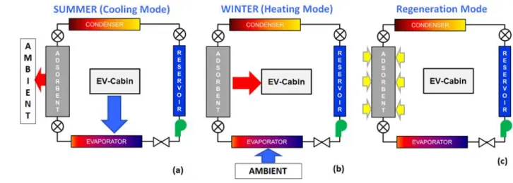
Adsorption based heat pumps and refrigeration systems can directly utilize primary thermal energy sources for operation. This allows the use of solar, waste heat, geothermal energy etc. However, adsorption based systems have low COP values, and are typically bulky and heavy compared to conventional mechanical heat pumps. We are developing a compact and lightweight advanced thermo-adsorptive battery (ATB) for climate control in EVs to reduce the existing electrical battery climate control budget. In contrast to conventional vapor compression cycles (VCC), an adsorption based heating and cooling system is utilized, which is both compact and energy efficient. In addition, the proposed system will have zero ozone depletion potential since it utilizes water as the refrigerant. The overall concept to provide both heating in the winter and cooling in the summer is schematically illustrated in Figure 1. The refrigerant is supplied using a pump from a reservoir through an expansion valve to an evaporator where it vaporizes.
Figure 1. Schematic diagram of the overall heating/cooling system with arrows indicating the direction of heat transfer during (a) cooling mode in summer, (b) heating mode in winter, and (c) regeneration of the adsorption bed for subsequent heating/cooling cycles. The refrigerant is supplied from a reservoir through an expansion valve to an evaporator where it vaporizes. The spontaneous transport and adsorption of vapor in the adsorption bed releases heat, which is dissipated using a heat exchanger. In summer, the cabin interacts with the evaporator as shown in (a), while in winter the cabin is heated by the adsorbent as shown in (b). In both modes of operation, the bed is eventually saturated with refrigerant. The bed regeneration is carried out with a thermal source as indicated in (c). The vapor
desorbed from the bed is transported to the condenser during regeneration, where it is condensed and subsequently collected in the reservoir for subsequent cycles of operation.
Unlike a VCC, the transport of vaporized refrigerant from the evaporator to the adsorbent bed takes place passively, i.e., without the utilization of any external means of vapor transport or compression. The spontaneous transport and the subsequent adsorption of vapor in the adsorption bed releases heat, which can be dissipated using either an air-based or a liquid-based heat exchanger in contact with the bed. In summer or cooling mode (Figure 1(a)), the EV cabin-air interacts thermally with the evaporator for cooling, while in winter or the heating mode (Figure 1(b)), the EV cabin is heated by the adsorbent bed. In both modes of operation, the bed is eventually saturated with the refrigerant. After saturation, the bed can be recharged by providing heat from a thermal source, which can be waste heat, solar energy or electrical power at a recharge station (Figure 1(c)). The vapor desorbed from the bed is then transported to the condenser, where it is condensed and eventually collected in the reservoir for subsequent cycles of heating or cooling.
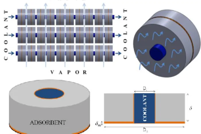
The overall design of the ATB based climate control system is illustrated in Figure 2. The ATB consists of an adsorption bed interfaced with liquid cooling. A phase-change heat exchanger (PHEX) is utilized, which functions as an evaporator as well as a condenser, depending on the mode of operation. During vehicle operation, the refrigerant (water) is pumped from a reservoir to the PHEX (evaporator) through an expansion valve. Vapor generated due to evaporation within the PHEX diffuses into the bed, where is it eventually adsorbed. Heat generated during the process of adsorption is dissipated using liquid cooling. During summer, the EV-Cabin is thermally interfaced with the PHEX to provide cooling (shown as dotted lines in Figure 2) and during winter, the Cabin is thermally interfaced with the bed for heating (shown as solid lines in Figure 2). When the vehicle is parked in a recharge
station, the adsorption bed is regenerated by the provision of thermal energy causing vapor desorption. The desorbed vapor diffuses back into the PHEX, which functions as a condenser for the regeneration mode. The condensate is transported back into the reservoir for subsequent use.
It is evident that the rate of cooling provided by the PHEX, or the rate of heating provided by the bed, relies on the net rate of vapor adsorption, which is controlled by transport characteristics and adsorption kinetics. In this study, we present a detailed computational analysis to predict the overall performance of the ATB based climate control system.
MATHEMATICAL MODELING OF ADSORPTION PROCESS
A two-dimensional, transient analysis is carried out to predict heat and mass transfer during the adsorption of vapor in a bed consisting of an adsorbent-binder composite structure illustrated in Figure 3. A detailed computational simulation is carried out to determine the effect of various operational and design parameters, which are discussed in the subsequent sections.
Vapor transport during adsorption
Transport of vapor within the adsorbent by advection and diffusion is given by the following equation,
𝜖 𝐶 𝑡 𝐶 𝜖𝐷𝑣 𝐶 ( 𝜖) 〈 𝐶
𝑡〉 (1)
Figure 3. Schematic diagrams illustrating an axisymmetric geometry of adsorbent attached to a circular copper plate.
A concentrically situated coolant line dissipates heat generated during adsorption. The net heat dissipated from
the bed can be altered by changing the flow rate and temperature of the coolant. Di = 0.01 m denotes the
diameter of the concentrically located coolant pipe used to maintain the adsorbent at a low temperature, while Do =
0.04 m represents the outer diameter of the adsorbent annulus. = 0.0015 m denotes the thickness of the adsorbent supported on the annular fin of thickness, m =
50 µm. Figure 2. Coolant and refrigerant flow diagram illustrating the
operation of the battery in the heating (solid lines), and cooling (dotted lines) modes. Refrigerant supplied from the reservoir
evaporates in the phase-change heat exchanger (PHEX) by absorbing heat. The vapor generated is diffuses into the bed, where it is exothermically adsorbed. The cabin can either be heated or cooled by interfacing it with the bed or the PHEX,
where 𝐶 represents the concentration of vapor phase, and 𝐶𝝁
denotes the concentration of the adsorbed vapor at any location within the adsorption bed. The velocity, intracrystalline diffusivity and adsorbent porosity are denoted by , 𝐷𝑣 and 𝜖,
respectively. The velocity in the adsorption bed is related to the permeability as 𝐾
𝜇 𝑝. Permeability, 𝐾 is calculated as
𝐾 150(1−𝜖)(2𝑅) 𝜖 [5], where 𝑅𝑐 denotes the characteristic radius of
the adsorbent crystal. The pressure distribution within the bed can be derived from the equation of state, 𝑝 𝐶𝑅̂𝑇, where 𝑅̂ denotes the universal gas constant. Consequently, the velocity of permeation can be calculated using the concentration and temperature gradients, as shown below.
𝐾𝑅̂𝜇 ( 𝐶 𝑇) (2)
The mean free path for vapor molecules in the bed, at typical operating conditions during adsorption (300-370 K and 760 Pa), is in excess of 10 µm. Consequently, the vapor diffusion within the bed for these operating conditions is dominated by Knudsen diffusion since the mean free path of vapor molecules is much larger than the characteristic pore size of the adsorbent bed. Therefore, the diffusivity is given by 𝐷𝑣 𝐷𝑣,𝑜(𝑇/𝑇𝑜)1/2, where 𝐷𝑣,𝑜 is the vapor diffusivity in a pore of diameter, 𝑑𝑝 at
an operating temperature, 𝑇𝑜. For example, 𝐷𝑣,𝑜 = 9.9×10⁻⁴
m2/s, for a pore diameter of 𝑑𝑝 = 0.45 µm at 𝑇𝑜 = 300 K. In equation (1) and in subsequent passages, 〈 〉 denotes a volumetrically averaged variable. Volumetrically averaged rate of adsorption at any location within the bed is given by 〈 𝐶
𝑡〉.
In a single adsorbent crystal, the average rate of adsorption is given by the following equation.
⟨ 𝐶𝜇 𝑡⟩ 1∫ 𝐷𝜇 𝐶𝜇 ̂ 𝑑 (3)
Assuming a parabolic distribution of vapor concentration within a spherically shaped crystal, the average rate of adsorption can be obtained using the linear driving force model [6],
〈 𝐶 𝑡〉 15𝑅 𝐷𝜇(𝐶 〈𝐶𝜇〉) (4)
where 𝐷𝜇 represents the intracrystalline diffusivity of vapor in
an adsorbent crystal, which is assumed as a sphere of radius 𝑅𝑐
= 2.5 µm. Variation in 𝐷𝜇 with temperature is given by 𝐷𝜇 𝐷𝜇0𝑒−𝐸 /𝑅̂𝑇(1−𝑇/𝑇), where 𝐸𝜇 = 28 kJ/mol [6], and 𝑅̂ is
the universal gas constant. 〈𝐶𝜇〉 represents average
concentration of the adsorbed vapor. 𝐶 represents the
equilibrium concentration of vapor adsorbed in the crystal surface, which is a function of local adsorbent temperature and vapor pressure, 𝑝 or concentration, 𝐶 surrounding the crystal. The equilibrium concentration of the adsorbed vapor is
calculated using the adsorption isotherm given by the following equation [7].
𝐶 (1 (𝑏𝑝)𝑎𝑝) ⁄ (5)
where 𝑎 𝑎0𝑒Ε/𝑇, 𝑏 𝑏0𝑒Ε/𝑇 and 𝜏 𝜏0 𝑐0/𝑇. The vapor
adsorption capacity or uptake can be calculated as 𝜔 𝑀𝐶 /𝜌𝑐, where 𝑀 = 0.018 kg/mol is the molecular weight of
water and 𝜌𝑐 = 1470 kg/m3 is the crystal density of zeolite 13X
[8].
Heat Transfer during Adsorption
The temperature distribution, 𝑇 at any instant within the bed is given by the following equation.
〈𝜌𝑐𝑝〉 𝑇 𝑡 〈𝜌𝑐𝑝〉 𝑢 𝑇 〈𝑘〉 𝑇 ℎ𝑎𝑑( 𝜖) 〈 𝐶
𝑡〉 (6)
where, ℎ𝑎𝑑 is the heat of adsorption, with an average value ~3.13×10⁶ J/kg . The average volumetric heat capacity, 〈𝜌𝑐𝑝〉 is
given by,
〈𝜌𝑐𝑝〉 ( 𝜖)𝜌𝑐𝑐𝑝,𝑐 ( 𝜖)𝑀𝐶𝜇𝑐𝑝,𝜇 𝜖𝑀𝐶𝑐𝑝,𝑣 (7)
𝜌𝑐 and 𝑐𝑝,𝑐 = 836 J/kgK [6] are the crystal density and the
specific heat of the dry adsorbent, 𝑐𝑝,𝜇 = 4180 J/kgK and 𝑐𝑝,𝑣
are the specific heat of the adsorbed and vapor phase, respectively. 𝑐𝑝,𝑣 is calculated as a function of temperature
using steam properties [9]. The packing density, 𝜌𝑎 can be
related to the crystal density, 𝜌𝑐 of the adsorbent as 𝜌𝑎 𝜌𝑐( 𝜖). The average thermal conductivity, 〈𝑘〉 is calculated
using the following equation [10]:
〈 〉 ( √ 𝜖) 1−√𝜖
(√ 𝜖 √𝜖 ) [(1− ) (1− ) 1 1− −1] (8)
where, 𝛽 [( 𝜖)/𝜖]0 9676 and 𝜆 𝑘
𝑣/𝑘𝑧. 𝑘𝑣 and 𝑘𝑧 are the
vapor and dry adsorbent thermal conductivity. 𝑘𝑣 is obtained as
a function of temperature using steam properties. 𝑘𝑧 is varied in
order to provide different values of 〈𝑘〉 to study its effect on net adsorption.
Initial Condition
The bed is assumed to be at uniform temperature and pressure of 𝑇𝑖 = 333.15 K (60 oC) and 𝑝𝑖 = 1 Pa, respectively. Therefore, the initial vapor concentration within the bed is given by 𝐶𝑖 𝑝𝑖/𝑅𝑇𝑖 and the concentration of the adsorbed phase is given by 𝐶µ𝑖 𝐶 𝑖, calculated using Equation (5).
Boundary Conditions
For the computational domain shown in Figure 3, the boundary conditions are given as follows. At 𝑟 𝐷𝑖⁄ , the 2
walls are assumed to be impermeable to vapor. Consequently, (𝐷𝑣 𝐶 𝑢𝐶) 0, which denotes a zero flux boundary
condition. Due to heat dissipation by coolant flow, heat conduction at 𝑟 𝐷𝑖⁄ is given by (〈𝑘〉 𝑇) ℎ2 𝑎𝑓(𝑇𝑎𝑓
ℎ𝑎𝑓(𝑇𝑎𝑓 𝑇), where ℎ𝑎𝑓 = 5000 W/m2K and 𝑇𝑎𝑓 = 333.15 K
are the heat transfer coefficient and mean coolant temperature, respectively. Although an annulus structure shown in Figure 3 is used as the characteristic geometry for analysis, it should be noted that energy storage could be implemented with any suitable unit cell geometry. To account for the variability in shapes, the boundary at 𝑟 𝐷𝑜⁄ is assumed to contribute 2 negligibly to heat mass transfer. Consequently ̂ (𝐷𝑣 𝐶
𝐶𝑢) 0 and ̂ (〈𝑘〉 𝑇) 0. At the interface of the adsorbent and the annular fin, 𝑧 𝛿𝑚, a zero vapor flux boundary
condition is assigned, given as ̂ (𝐷𝑣 𝐶 𝐶𝑢) 0.
Continuity in heat flux and temperature at the interface between the adsorbent and the metal substrate is implied. At 𝑧 0 due to symmetry, 𝑇 0. At the free surface, 𝑧 𝛿𝑚 𝛿, the
concentration of vapor is given as 𝐶 𝐶𝑏, which is related to
system pressure as 𝐶𝑏 𝑝𝑣/𝑅̂𝑇, and the concentration of the
adsorbed phase is given as 𝐶𝜇 𝐶𝜇𝑏 , calculated using
Equation (5). The free surface is also assumed to contribute negligibly towards heat transfer. Consequently, at 𝑧 𝛿𝑚 𝛿, ̂ 〈𝑘〉 𝑇 0. The adsorption and transport characteristics of commercial zeolite 13X were initially determined. The property values were then utilized in the computational study to predict adsorption kinetics. We then quantitatively demonstrate how enhancements in certain transport and adsorption properties can improve the overall performance of energy storage.
CHARACTERIZATION OF PROPERTIES Adsorption capacity of zeolite 13X
Water vapor adsorption experiments are performed on an Autosorb IQ2 sorption instrument from Quantachrome Instruments. Each isotherm was measured on a thermally activated adsorbent sample. Approximately 30-40 mg was weighed into a quartz cell and pretreated at about 1.4 mTorr and 400 °C for 12 hrs. After cooling the sample under vacuum to the temperature of adsorption, the void volume was measured by adsorbing He. The dosing manifold, valves and gauges were temperature controlled at 50 °C. The textural properties of the zeolites were characterized by means of N2 BET surface
analyzer (Micromeritics ASAP 2020 BET) at -196 °C.
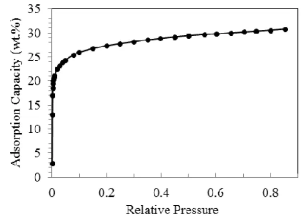
Water vapor adsorption isotherm of 13X zeolite (Sigma-Aldrich) at 25 °C is shown in Figure 4. It belongs to Isotherm Type I, typical for hydrophilic microporous zeolite materials. It has a water vapor uptake capacity of 22.5 wt.% at 25 °C and a relative pressure (𝑅𝑃 𝑝𝑣/𝑝𝑠𝑎𝑡(25 oC)) of 2%. In contrast, at
20% RP, its water vapor adsorption capacity increases to 27.3 wt.% at the same operating temperature. Based on N2 sorption
measurement at -196 °C, the 13X zeolites had a micropore volume and BET surface area of 0.28 ml/g and 646.66 m2/g, respectively. The saturation adsorption capacity of 30.8 wt.% is in agreement with its inherent microporosity. For the
computational analysis, the equilibrium concentration of the adsorbed vapor is calculated using Equation (5), where 𝑎0 =
3.634×10⁻⁹ mol/kgPa, 𝑏0 = 2.408×10⁻¹⁰ 1/ Pa, 𝑐0 = -4.199 K,
and 𝜏0 = 0.3974 [7].
Figure 4. Water vapor adsorption isotherm of zeolite 13X (Sigma-Aldrich) at 25 °C.
Thermal conductivity of adsorbent-binder composite
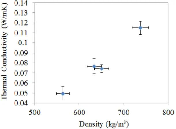
In order to measure the average thermal conductivity of zeolite 13X, the laser flash method [11] requires packing the material as a cylindrical disk of fixed diameter. A desired amount of dehydrated zeolite 13X (450°C for 12 hours) is placed in a stainless steel mold, followed by mechanical densification using a hydraulic press (~ 40 MPa) to result in cylindrically shaped sample disks. The effective density of the fabricated disk was calculated by measuring the overall mass and volume of the dried zeolite disk. The thermal transport performance of the fabricated disk was characterized by LFA with 1064 nm wavelength laser and differential scanning calorimetry (DSC), to measure the specific heat of zeolite 13X between 50°C and 200°C. The thermal conductivity, 〈𝑘〉 is given in Figure 5, which shows an increase with density of the synthesized sample. The thermal conductivity of pure zeolite 13X, without the combination of binders are found to be quite low ~0.1 W/mK.
Measurement of adsorbent porosity
Equations (1) and (6) show that the porosity can significantly affect the transport characteristics during adsorption. Consequently, a preliminary characterization of porosity was carried out using a simple experimental setup. A preliminary characterization of porosity was carried out using a simple experimental setup. The measurement of porosity were carried out using a 2 inch long stainless steel tube with a sample of known density and thickness. The samples were prepared using a measured mass of zeolite 13X in powder form at ambient conditions. After placing the zeolite crystals in the tube and application of variable pressure, compressed samples with a range of densities were fabricated. The tube was connected in series to a flow meter, high-pressure tank filled with Argon, and a pressure transducer.
Experiments were carried out by measuring the flow rate and pressure drop across samples. The porosity of the samples were then calculated using the Kozeny-Carman equation [12]. The initial water uptake of zeolite 13X was assumed to be 27% at relative humidity of 20%. This allows discounting the weight of the adsorbed vapor during the calculation of the density of the sample fabricated. The sphericity in the Kozeny-Carman equation for zeolite 13X was assumed as 0.846 corresponding to an octahedron. Figure 6 compares the porosity of samples obtained by compressing zeolite 13X powder as a function of the density of samples fabricated. The results from experiment were compared with a theoretical estimate, which relates density of fabricated sample with crystal density as described before as 𝜌𝑎 𝜌𝑐( 𝜖), wherein the crystal density, 𝜌𝑐 is
taken as 1470 kg/m3.
Figure 5. Average thermal conductivity of zeolite 13X measured as a function of density.
Figure 6. Experimental characterization of porosity of various samples fabricated by compression of zeolite 13X powder.
Results from experiment were compared with theoretical estimate, which relates density of fabricated sample with crystal
density as 𝜌𝑎 𝜌𝑐( 𝜖), wherein crystal density, 𝜌𝑐 is 1470
kg/m3.
RESULTS AND DISCUSSION
Computational simulation of adsorption kinetics
The governing equations were solved to predict spatial variation in the temperature profile and overall rate of vapor adsorption. In order to estimate the effect of various parameters computationally, the net variation in the adsorption capacity is calculated as a function of time. The volumetrically averaged rate of adsorption for a given bed geometry, thermophysical properties and operating conditions is calculated using the following equation
〈𝑚′′′̇ 〉 1∫( 𝜖) 〈 𝐶 𝑡〉 𝑑𝑉 (8) where 〈𝜕𝐶𝜇⁄ 〉 is given by Eq. (5), and 𝑉 is the volume given 𝜕𝑡
by 𝜋 4⁄ (𝐷𝑜2 𝐷𝑖2)𝛿. The volumetrically averaged
temperature, 〈𝑇〉 of the adsorbent is calculated using the following equation.
〈𝑇〉 1∫ 𝑑𝑉 (9)
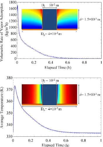
Figure 7(a) shows the volumetrically averaged rate of vapor adsorption (kg/m3h) for the geometry illustrated in Figure 3. The inset shows a snapshot of the spatial variation in vapor uptake at t = 0.2 h, with a maximum of 0.19 kg/kg at the surface exposed to vapor and a minimum of 0.11 kg/kg at the adsorbent/metal-substrate interface. The regions farther from the adsorbent surface are saturated gradually, as mass diffusion transports vapor to the remotely located interface. Figure 7(b) shows the spatial variation in the temperature of the adsorbent with a range of 334 to 349 K, captured at t = 0.2 h. In all the computational predictions presented herein, the temperature of the liquid in the concentric coolant line is held fixed at 𝑇𝑎𝑓 =
333.15 K.
Figure 7 shows the temporal variation in the adsorption capacity and temperature of a typical thermal energy storage system. Starting at dry conditions, when the adsorbent is instantaneously exposed to a constant vapor pressure, 𝑝𝑣 the
initial adsorption rate is significantly high. Consequently, a sudden increase in the adsorbent temperature is also observed during the initial stages of adsorption. A subsequent drop in adsorption rate is then observed as the vapor encounters diffusion resistance within the bed. Eventually, both temperature and the adsorption capacity reach saturation conditions. These results clearly indicate that the performance of a typical thermal energy storage system is temporally sensitive. Therefore, an active control of vapor supply rate will be desirable to deliver a constant rate of cooling or heating, and prolong the cycle duration.
Figure 7. Volumetrically averaged rate of (a) vapor adsorption, and (b) temperature as a function of time for a geometry illustrated in the inset. Inset in (a) shows a snapshot of spatial variation in vapor uptake, ranging between 0.11 (shown as dark
blue) to 0.19 kg/kg (shown as dark red) at t = 0.2 h. Inset in (b) shows the spatial variation in temperature at t = 0.2 h, with a maximum value of 349 K (shown as dark red), and a minimum
of 334 K (shown as dark blue).
Effect of net adsorption capacity on performance
The choice of adsorbent and refrigerant is crucial for providing climate control at the desired temperature. For instance, with pure water as the refrigerant, it is necessary to maximize adsorption capacity at relatively low operating pressures (~ 750 Pa) to deliver air-conditioning at moderately low temperatures (~ 5 oC). Consequently, a Type-1 adsorption isotherm is generally preferred for using water as the refrigerant. An example of Type-1 isotherm is adsorption of water vapor in zeolite 13X, as shown in Figure 4. In order to illustrate the importance of adsorption capacity in thermal energy storage system, the water-zeolite 13X combination is compared with adsorbents, which in theory can provide comparatively higher adsorption capacities. The adsorbents, denoted as Xi (i = 1 to 4), are assigned isotherms (Equation (5))
to deliver higher adsorption capacities, specifically, in positive
increments of 25% compared to the baseline adsorption capacity of Zeolite 13X, as shown in Figure 8 (a).
Figure 8. (a) The isotherms comparing the vapor adsorption capacity of zeolite 13X with adsorbents demonstrating Type-1
characteristic. The adsorption capacities are arranged in 25% increments in comparison to zeolite 13X.
Figure 8(b) shows the volumetric rate of adsorption using zeolite 13X, and the adsorbents Xi. With similar thermophysical
and transport characteristics, the adsorbents differ only in their overall equilibrium adsorption capacities. It is clear from Figure 8(b) that materials with higher adsorption capacities support a higher adsorption rates and a longer operational time. Consequently, a system using adsorbents with higher capacities can either prolong the duration of operation or support a higher rate of heating or cooling. The inset in Figure 8(b) shows the time-averaged volumetric adsorption rate as a function of the equilibrium adsorption capacity at 𝑇 300 K and 𝑝𝑣 760
Pa. Averaged over 60 minutes of operation, the average adsorption rates are found proportional to the equilibrium adsorption capacities. From inset of Figure 8(b), it can be concluded that zeolite 13X can deliver an average cooling rate of ~0.1 kW/liter, and adsorbents with twice the adsorption capacity can deliver cooling rates of ~0.2 kW/liter. Assuming a 40% higher heat of adsorption compared to heat of evaporation,
the average heating rates are 0.14 kW/liter for zeolite 13X, and 0.28 kW/liter for adsorbent X4. In summary, for higher heating
or cooling rates, it is desirable to utilize adsorbents with higher adsorption capacities at the desired operational conditions. For instance, the operational conditions with water as refrigerant for moderate cooling (~ 5 oC) and heating (~ 60 oC), correspond to vapor pressures close to ~ 750 Pa. In the absence of such materials, a higher performance will necessitate a shorter operational time before system recharge or larger volume, compromising the compactness of the system.
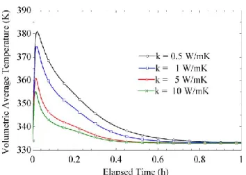
Effect of adsorbent thermal conductivity
The average thermal conductivity of adsorbents is also an important factor in thermal energy storage systems since it controls the operational temperature during adsorption. A lower thermal conductivity can lead to undesirable and sub-optimal performance. For example, the adsorption capacity of zeolite 13X shows depreciation with increase in temperature (as shown in Figure 9(a)). Zeolite 13X provides an adsorption capacity of ~0.22 kg/kg at 300 K and a relative pressure, 𝑝/𝑝𝑠𝑎𝑡 of 0.1. A 10% reduction in adsorption capacity is observed when the adsorbent temperature is increased by 25%.
It is indeed possible to enhance the overall thermal conductivity of the adsorbent by utilizing high-k binding materials, such as microporous metallic foam, functionalized multi-walled carbon nanotubes, graphite, etc. while maintaining the same adsorption capacity. The effect of thermal conductivity on the operational temperature is determined by utilizing adsorption characteristics of zeolite 13X, but varying the average thermal conductivity of dry adsorbent. The geometry (Figure 3) and other parameters, including operating conditions are held constant in order to gauge the effect of thermal conductivity. Figure 9(b) shows the temporal variation in the volumetrically averaged temperature of the adsorbent for the design shown in Figure 3. The average as well as peak temperatures during adsorption can be reduced if the thermal conductivity of the bed is enhanced. This in turn will aid in maximizing both the adsorption rate and capacity of the bed.
Figure 9. (a) The equilibrium adsorption capacity of zeolite 13X as a function of relative pressure, 𝑝/𝑝𝑠𝑎𝑡and temperature,
𝑇, and (b) temporal variation in the average temperature, 〈𝑇〉 of the adsorbent as a function of thermal conductivity.
Effect of porosity on vapor transport
The porosity, 𝜖 can be varied by changing the parameters for the fabrication of an adsorbent bed. For instance, by using different binding materials and densification via the use of hydraulic press, adsorbent beds of different densities and porosities can be synthesized. A variation in the porosity of the adsorbent can result in different vapor transport characteristics. Random packing of spherical adsorbent crystals resulting in a bed with an overall porosity, 𝜖 corresponds to void volumes of varying sizes. The distribution of the characteristic size of the void spaces is given by the following equation [13].
𝑃(𝜒) 3( 𝜒)2𝜖( 𝜖)( 𝜖𝐻𝐶𝑃)
(𝜖 𝜖𝐻𝐶𝑃)
𝑒 𝑝 { (1−𝜖)(1−𝜖 )
(𝜖−𝜖 ) [( 𝜒) ]} ( )
𝑃(𝜒)𝑑𝜒 denotes the probability of finding a spherical void of diameter between 𝜒 and + d. 𝜒 is the ratio of the diameter of void space to the characteristic size of the adsorbent. 𝜖𝐻𝐶𝑃
denotes the porosity corresponding to the maximum packing density of a hexagonal closed packed structure. Using the probability distribution, the mean diameter of the spherical particles that can be accommodated in the void spaces is given by the following equation. Mean diameter, χavg as a function of
the overall porosity is shown in the Figure 10 (a). As expected, the average diameter of the voids in the adsorbent bed increases with the overall porosity, 𝝐.
𝜒𝑎𝑣𝑔 1𝜖∫ 𝜒 𝑃(𝜒) 𝜒0 (9)
Using this formulation to calculate the mean pore diameter, the coefficient of vapor diffusivity due to Knudsen diffusion can be determined as a function of the porosity. An increase in the
porosity from 0.3 to 0.7 can result in 14x enhancement in the intercrystalline vapor diffusivity. Although a larger porosity can improve vapor transport, it also results in lower volumetric energy density due to increase in the void volume. Therefore, compaction or densification of the adsorbent is necessary to maximize energy density of the overall system.
Using an adsorption bed with lower porosity, a higher rate of vapor adsorption can be delivered, as shown in Figure 10(b). Clearly, a bed with lower porosity can yield volumetrically higher thermal storage capacity. On the other hand, a smaller initial spike and a gradual decrease in the volumetric rate of vapor adsorption are both indicators of larger diffusion resistance for lower porosity beds. However, for the design illustrated in Figure 3, a lower intercrystalline diffusivity due to lower porosity is not significantly detrimental to the overall performance, as indicated in Figure 10 (b). It is therefore important to choose overall diffusion length scale, 𝛿 suitably to account for lower intercrystalline diffusivity for lower porosity bed. For an overall operation time of 60 minutes, the inset in Figure 10 (b) shows a linear decrease in the temporally averaged rate of vapor adsorption versus increasing porosity.
With an overall porosity of 0.4, an average adsorption rate of 159.2 kg/m3h is expected, delivering a volumetric cooling rate close to ~ 0.1 kW/liter. A 50% enhancement in the porosity, although increases the vapor diffusivity within the bed, will deteriorate the cooling rate by ~30%.
SUMMARY AND CONCLUSIONS
Current state-of-the-art technologies for electric-power-train vehicle (PHEV and EV) climate control systems are inefficient and lead to a significant drain on the electric battery. We are developing a compact and lightweight advanced thermo-adsorptive battery (ATB) for climate control in EVs to reduce the existing electrical battery climate control budget. In contrast to conventional vapor compression cycles (VCC) and resistive heating, the ATB is energy efficient during use. In order to predict the performance of ATB, a two-dimensional, transient computational analysis is carried out. The computational study predicts the rate of heat and mass transfer during adsorption of vapor. The adsorption capacity, thermal conductivity and porosity of commercial zeolite 13X were determined. The performance predictions were then carried out for zeolite 13X. We demonstrate how enhancements in certain transport and adsorption properties can improve the overall performance of adsorption based thermal energy storage for heating and cooling.
The water-vapor adsorption on zeolite 13X is characterized by a Type I isotherm, which is typical for a hydrophilic microporous zeolite material. At 25 °C it has vapor adsorption capacities of 22.5 wt. % and 27.3 wt. %, at relative pressures of 2 % and 20 %, respectively. The computational study shows that materials with higher adsorption capacities support higher adsorption rates and a longer operational time. Consequently, a system using adsorbents with higher capacities can either prolong the duration of operation or support a higher rate of heating or cooling. For a simple bed design illustrated in Figure 3, and an operational time of 60 minutes, zeolite 13X can deliver an average volumetric cooling and heating rates of ~0.1 kW/literadsorbent and 0.14 kW/literadsorbent, respectively. However,
overall performances were found to scale linearly with the adsorption capacity. With materials delivering twice the adsorption capacity as zeolite 13X, cooling and heating rates close to ~0.2 kW/literadsorbent and 0.28 kW/literadsorbent,
respectively can be delivered for a total operational time of 60 minutes.
The average thermal conductivity of adsorbents is also an important factor in thermal energy storage systems since it controls the operational temperature during adsorption. A lower thermal conductivity can lead to undesirable and sub-optimal performance. For example, a 10% reduction in adsorption capacity is observed for zeolite 13X when the temperature is increased by 25%. The average thermal conductivity of pure zeolite 13X, without the combination of conductive binders are found to be quite low ~0.1 W/mK. The average as well as peak temperatures during adsorption can be reduced if the thermal conductivity of the bed is enhanced. This in turn will assist in maximizing both the adsorption rate and capacity of the bed. Figure 10. (a) Average non-dimensional diameter, 𝜒avg of the
spherical voids within a bed of randomly packed spheres of radius, 𝑅𝑐 as a function of the overall porosity of the bed, and (b)
The volumetric rate of vapor adsorption as a function of porosity.
We envision enhancement in the overall thermal conductivity of the adsorbent by utilizing high-k binding materials, such as microporous metallic foams, functionalized multi-walled carbon nanotubes, graphite, etc. while maintaining the same adsorption capacity.
Using an adsorption bed with lower porosity, a higher rate of vapor adsorption can be delivered. A bed with lower porosity can yield volumetrically higher thermal storage capacity. For instance, with an overall porosity of 0.4, an average adsorption rate of 159.2 kg/m3h is expected, delivering a volumetric cooling rate close to ~ 0.1 kW/ literadsorbent. A 50% enhancement
in the porosity will deteriorate the cooling rate by ~30%. Indeed, a larger diffusion resistance is expected for a bed with lower porosity. It is therefore important to choose overall diffusion length scale, 𝛿 to account for lower intercrystalline diffusivity for lower porosity bed. This will ensure maximum utilization of the adsorption capacity and consequently a higher performance.
ACKNOWLEDGMENTS
The authors gratefully acknowledge the support of Advanced Research Projects Agency-Energy (ARPA-E) with Dr. Ravi Prasher and Dr. James Klausner as program managers for providing financial support.
REFERENCES
[1] S. K. Fischer and J. Sand, "Total environmental warming impact (TEWI) calculations for alternative automotive air-conditioning systems," SAE Technical Paper, 1997.
[2] R. A. Barnitt, A. D. Brooker, L. Ramroth, J. Rugh, and K. A. Smith, "Analysis of Off-Board Powered Thermal Preconditioning in Electric Drive Vehicles," National Renewable Energy Laboratory, Golden, CO, 2010. [3] K. A. Gschneidner Jr, V. Pecharsky, D. Jiles, and C. B.
Zimm, "Development of vehicle magnetic air conditioner (VMAC) technology. Final report," Iowa State University, Ames, Iowa (US); Astronautics Corporation of America, Astronautics Technology Center, Madison, WI (US)2001.
[4] R. de Boer and S. Smeding, "Thermally Operated Mobile Air Conditioning Systems," Timeline, vol. 2009, 2005.
[5] R. B. Bird, W. E. Stewart, and E. N. Lightfoot, "Transport phenomena. 2002," JohnWiley & Sons, New York.
[6] K. Chan, C. Y. H. Chao, G. Sze-To, and K. Hui, "Performance predictions for a new zeolite 13X/CaCl2
composite adsorbent for adsorption cooling systems," International Journal of Heat and Mass Transfer, vol. 55, pp. 3214-3224, 2012.
[7] Y. Wang and M. D. LeVan, "Adsorption equilibrium of carbon dioxide and water vapor on zeolites 5A and 13X and silica gel: Pure components," Journal of Chemical & Engineering Data, vol. 54, pp. 2839-2844, 2009.
[8] S. M. Auerbach, K. A. Carrado, and P. K. Dutta, Handbook of zeolite science and technology: CRC, 2003.
[9] A. H. Harvey, A. P. Peskin, and S. A. Klein, "NIST/ASME steam properties," NIST Standard Reference Database, vol. 10, 2000.
[10] C. Hsu, P. Cheng, and K. Wong, "Modified Zehner-Schlunder models for stagnant thermal conductivity of porous media," International Journal of Heat and Mass Transfer, vol. 37, pp. 2751-2759, 1994.
[11] W. Parker, R. Jenkins, C. Butler, and G. Abbott, "Flash method of determining thermal diffusivity, heat capacity, and thermal conductivity," Journal of Applied Physics, vol. 32, pp. 1679-1684, 1961. [12] M. Kaviany, "Principles of heat transfer in porous
media," 1991.
[13] M. Alonso, E. Sainz, F. Lopez, and K. Shinohara, "Void-size probability distribution in random packings of equal-sized spheres," Chemical engineering science, vol. 50, pp. 1983-1988, 1995.