HAL Id: hal-01416192
https://hal.archives-ouvertes.fr/hal-01416192
Submitted on 28 May 2020
HAL is a multi-disciplinary open access
archive for the deposit and dissemination of
sci-entific research documents, whether they are
pub-lished or not. The documents may come from
teaching and research institutions in France or
abroad, or from public or private research centers.
L’archive ouverte pluridisciplinaire HAL, est
destinée au dépôt et à la diffusion de documents
scientifiques de niveau recherche, publiés ou non,
émanant des établissements d’enseignement et de
recherche français ou étrangers, des laboratoires
publics ou privés.
Distributed under a Creative Commons Attribution - NonCommercial - ShareAlike| 4.0
Centrosome centering and decentering by microtubule
network rearrangement
G. Letort, F. Nedelec, L. Blanchoin, M. Thery
To cite this version:
G. Letort, F. Nedelec, L. Blanchoin, M. Thery. Centrosome centering and decentering by microtubule
network rearrangement. Molecular Biology of the Cell, American Society for Cell Biology, 2016, 27
(18), pp.2833 - 2843. �10.1091/mbc.E16-06-0395�. �hal-01416192�
MBoC |
ARTICLE
Centrosome centering and decentering
by microtubule network rearrangement
ABSTRACT The centrosome is positioned at the cell center by pushing and pulling forces transmitted by microtubules (MTs). Centrosome decentering is often considered to result from asymmetric, cortical pulling forces exerted in particular by molecular motors on MTs and controlled by external cues affecting the cell cortex locally. Here we used numerical simula-tions to investigate the possibility that it could equally result from the redistribution of push-ing forces due to a reorientation of MTs. We first showed that MT glidpush-ing along cell edges and pivoting around the centrosome regulate MT rearrangement and thereby direct the spatial distribution of pushing forces, whereas the number, dynamics, and stiffness of MTs determine the magnitude of these forces. By modulating these parameters, we identified different regimes, involving both pushing and pulling forces, characterized by robust centro-some centering, robust off-centering, or “reactive” positioning. In the last-named conditions, weak asymmetric cues can induce a misbalance of pushing and pulling forces, resulting in an abrupt transition from a centered to an off-centered position. Taken together, these results point to the central role played by the configuration of the MTs on the distribution of pushing forces that position the centrosome. We suggest that asymmetric external cues should not be seen as direct driver of centrosome decentering and cell polarization but instead as induc-ers of an effective reorganization of the MT network, fostering centrosome motion to the cell periphery.
INTRODUCTION
In many cells, the centrosome is positioned at the geometric center of the cell, across a wide range of conditions: in cultured cells (Burakov et al., 2003), whether they have circular or elongated shapes (Hale et al., 2011) or symmetric or asymmetric adhesion pat-terns (Théry et al., 2006), in migrating cells (Gomes et al., 2005; Dupin et al., 2009), and in fertilized eggs (Wühr et al., 2010; Kimura and Kimura, 2011a; Minc et al., 2011). The robustness of this
centering mechanism has been proposed to rely on the contribution of several types of mechanical forces acting on microtubules (MTs) by pushing and pulling on cytoplasmic organelles and cell borders, all contributing to stabilize the centrosome at the cell center (Zhu
et al., 2010; Laan et al., 2012a). However, in vivo, the centrosome is
mostly found at the cell periphery (Tang and Marshall, 2012). In-deed, in most differentiated cells, the centrosome is anchored to the plasma membrane, where it serves as a structural base for the primary cilium (Reiter et al., 2012). This simple consideration sug-gests that centrosome–MT networks not only have robust centering properties but also have efficient off-centering capacities. A global understanding of MT network geometry and centrosome position-ing should therefore include the strikposition-ing ability of this system to switch easily from a centering to an off-centering regime.
External cues are usually considered as the main driver of centro-some decentering. Indeed, centrocentro-some displacement to the cell periphery can be triggered by an asymmetric cue such as contact with a neighboring cell (Rodriguez-Fraticelli et al., 2012) or a target
Monitoring Editor Alex Mogilner New York University Received: Jun 13, 2016 Revised: Jul 11, 2016 Accepted: Jul 11, 2016
This article was published online ahead of print in MBoC in Press (http://www .molbiolcell.org/cgi/doi/10.1091/mbc.E16-06-0395) on July 20, 2016.
*Address correspondence to: Gaëlle Letort ([email protected]), Manuel Théry ([email protected]).
© 2016 Letort et al. This article is distributed by The American Society for Cell Bi-ology under license from the author(s). Two months after publication it is available to the public under an Attribution–Noncommercial–Share Alike 3.0 Unported Creative Commons License (http://creativecommons.org/licenses/by-nc-sa/3.0). “ASCB®,” “The American Society for Cell Biology®,” and “Molecular Biology of the Cell®” are registered trademarks of The American Society for Cell Biology. Abbreviation used: MT, microtubule.
Gaëlle Letorta,*, Francois Nedelecb, Laurent Blanchoina,c, and Manuel Thérya,c,*
aCytoMorpho Lab, Biosciences and Biotechnology Institute of Grenoble, UMR5168, CEA/INRA/CNRS/Université
Grenoble-Alpes, 38054 Grenoble, France; bCell Biology and Biophysics Unit, European Molecular Biology Laboratory,
69117 Heidelberg, Germany; cCytoMorpho Lab, Hopital Saint Louis, Institut Universitaire d’Hematologie, UMRS1160,
MT explicitly and solve the system correctly (Pinot et al., 2009; Maly and Maly, 2010; Wu et al., 2011).
To explore the balance between decentering and centering forces and tentatively reveal some relevant cellular parameters that would be interesting to focus on experimentally, we used numerical simulations. This approach allowed us to consider the effect of several factors that are likely to contribute to the regulation of force distribution. We ex-amined microtubule bending and reorientation and basic parameters such as MT number, polymerization dynamics, and stiffness for their ability to break MT network symmetry. In this way, we identified the possible changes in network architecture that might misbalance push-ing and pullpush-ing forces and promote centrosome decenterpush-ing.
RESULTS
Centrosome positioning mechanisms are challenging to study be-cause numerous factors such as cell shape, MT properties, or inter-acting proteins intervene and vary in different cell types and experi-mental conditions. Furthermore, there is currently no experiexperi-mental way to measure the mechanical forces experienced by MTs in vivo, precluding the mapping of the spatial distribution of pushing and pulling forces that can be used for centering. Here we performed simulations with Cytosim software (Nedelec and Foethke, 2007). This cytoskeleton simulator is based on a Langevin dynamics ap-proach and offers the possibility to take into account numerous components in minimal computational time due to a semi-implicit numerical integration scheme (Kozlowski et al., 2007; Loughlin
et al., 2010, 2011; Ward et al., 2014).
We simulated pure centrosomal arrays in which all MTs are at-tached to a common center at their minus ends (Supplemental Figure S1). The angular distribution of MT nucleation is isotropic. We simulated systems containing one centrosome composed of 100 MTs for 400 s. MT growth followed the classical two-state dynamic instability model (see Table 1 and Material and Methods for numeri-cal parameters). MTs were confined to regular geometries repre-senting different idealized cell shapes. They could bend as linear elastic beams and thus follow Euler’s buckling theory. Entities that could bind/unbind and move along MTs were added to simulate the action of minus end–directed motors. Centrosome displacement is opposed by a viscous drag calculated to match the experimental observations. MTs growing against geometrical boundaries pro-duced pushing forces, whereas minus end–directed motors gener-ated the pulling forces (Supplemental Figure S1). By simply monitor-ing the position of the centrosomes, we could deduce whether the tested conditions resulted in a net centering or decentering effect. Contribution of pulling forces
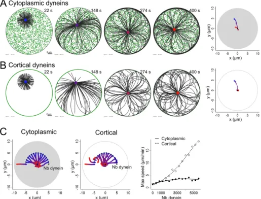
We first compared two scenarios in which motors such as dynein molecules are either distributed in the cytoplasm (Figure 1A and Supplemental Movie S1) or anchored at the cortex (Figure 1B and Supplemental Movie S1), in a situation in which MTs can be longer than the cell radius. In both cases, centrosomes moved toward the cell center regardless of the number of dyneins (except in the ab-sence of motors; Figure 1C). Cortical distribution gave rise to a much faster centrosome motion (Figure 1C and Supplemental Figure S2). However, note that the simulations were done for an equal number of dyneins for both distributions, leading to highly different local den-sities: the higher number of cortical dyneins binding to MTs explained the difference in centrosome speed (Supplemental Figure S2).
To investigate further the effect of the cellular geometry on centrosome positioning, we switched to ellipsoidal, rectangular, and triangular geometries. We explored the two fundamental motor distributions by systematically varying the total number of motors in cell (Yi et al., 2013). Such a cue generally induces local MT capture
and the development of tension forces pulling the centrosome to-ward the cue (Combs et al., 2006; Kozlowski et al., 2007; Nguyen-Ngoc et al., 2007). However, for this mechanism to displace the centrosome up to the cell periphery, the decentering force associ-ated with the asymmetric signal should overcome the centering forces. In such a scenario, cells would have difficulties in responding to minor changes in their environment.
Here we explore the possibility that the centrosome–MT network can adopt more “reactive” conformations in which centrosome po-sition is stable but easily destabilized by a small change in MT orga-nization. In such a state, the centrosome is the converging point of centering and decentering forces of comparable magnitude. There-fore a mild change in an intrinsic critical parameter or a small exter-nal cue can be sufficient to trigger network reorganization and thus bias the force balance so that decentering forces win over and move the centrosome to the periphery.
Minus end–directed motors, such as dynein molecules, produce pulling forces along MT length when bound to cytoplasmic vesicles or selectively on MTs tips when bound to the cell cortex (Kimura and Kimura, 2011b). The cytoplasmic localization of dyneins un-doubtedly leads to a net centering force, since MTs that are longer on the side of the centrosome that is facing the more distant cell edge are pulled more strongly than MTs facing the closest cortex. The cytoplasmic pulling scenario also includes adherent cultivated mammalian cells with a flat (“fried egg”) geometry in which motors anchored on the basal surface of the cell can pull microtubules all along their side. The contribution of dyneins anchored at the cell cortex is less clear. Cortical dyneins may have opposite effects on an isotropic radial array of MTs, depending on MT length distribu-tion and dynein density relative to MTs (Laan et al., 2012b). MT pushing forces, generated by MT polymerization against the cell periphery, could also center or decenter the centrosome, depend-ing on whether MT tips can slide or not on the cortex and affect the overall network symmetry (Holy et al., 1997; Tran et al., 2001; Faivre-Moskalenko and Dogterom, 2002; Brito et al., 2005; Pinot
et al., 2009). The question of centrosome positioning has been
ex-plored with coarse-grained models (Théry et al., 2007; Zhu et al., 2010; Minc et al., 2011; Ma et al., 2014). With this approach, indi-vidual microtubules are not represented, and the force on the cen-trosomes is calculated as a sum of elementary forces calculated for each angular sector of the cell seen from the centrosome. This ap-proach assumes that microtubules are straight and that the ones reaching the cortex do so in the line of sight from the centrosome. Typically, molecular motors are also not represented, and one as-sumes that their contribution results either in a constant force, in the case in which motors pull MTs at their tip, or in a force that is proportional to the distance between the centrosome and the cor-tex, for motors pulling MTs on their side. Pushing forces are as-sumed to act purely radially and often to be equal to the threshold for Euler-type buckling. Under these assumptions, the resulting equations can be analyzed simply. In other words, MTs are generally assumed to be no longer than the cell size, and their deformation is not considered to depart from a straight configuration. This condi-tion might hold for early embryos or cells in a mitotic state, in which straight microtubules ensure the centering by pushing forces, and asymmetric distributions of cortical dyneins can induce the decen-tering (Grill et al., 2001; Garzon-Coral et al., 2016). In mammalian cells in interphase, however, MTs can be much longer and must bend to fit within the cell. This condition makes the coarse-grained approach impractical, but with modern computer hardware and state-of-the-art simulation methods, it is possible to consider every
are directed toward the centrosome, but they are directed away from it in the case of anisotropic distribution (Pavin et al., 2012). Therefore any parameters influencing MT spatial distribution, such as nucleation, dynamics, or forces that induce bending, are likely to play key roles in determining the direction of the net pushing force on the centrosome. MTs are in particular easily deflected by forces applied on their ends. The net force on the centrosome will depend on MT stiffness, the number of MTs, and their configurations.
To investigate these effects, we considered a radial array of flexi-ble MTs with their minus end anchored at the centrosome. MTs are anchored at regular angular intervals, such as to form an isotropic aster, but we tuned the angular stiffness of their anchorage to allow them to pivot at various degrees around their minus-end anchorage. In the basic setup, plus ends could glide along the edge of the cell, as the contact is considered to be frictionless, but by adding immo-bile anchors at the cortex that capture the plus ends and pin them, we can also prevent sliding. Thus varying the angular stiffness at the cen-trosomes and the strength of anchor points at the cortex enabled us to test the combinatorial effects of allowing or disabling minus-end pivoting and plus-end gliding (Figure 3A and Supplemental Movie S3). Initially, those simulations were performed in the absence of mi-nus end motor–associated pulling forces. As expected from MT the system to explore different ratios of motors to MTs. In the case
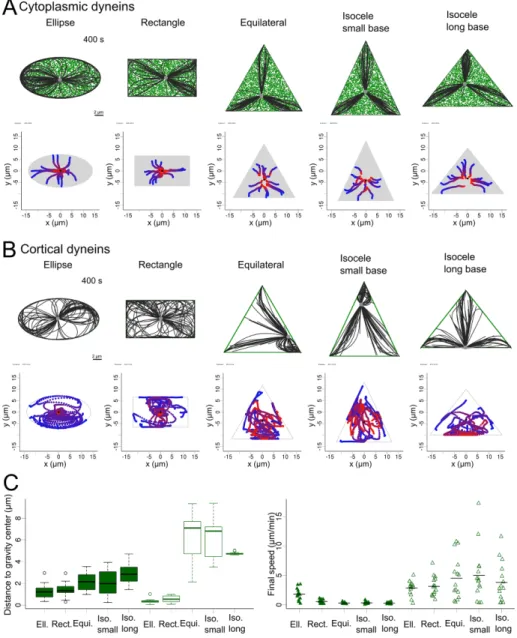
of cytoplasmic localization of dyneins, the centrosome moved to-ward the center of gravity of the shape for any given initial position and all tested geometries (Figure 2A and Supplemental Movie S2), consistent with experimental observation in sea urchin eggs (Minc
et al., 2011). In contrast, in the case of a cortical distribution,
centro-somes did not move toward the center of gravity in the triangular geometries. After fast and erratic displacements throughout the cell, the centrosome usually converged toward the middle of the longest edge, which contains more dyneins (Figure 2, B and C, and Supplemental Movie S2). As in the circular geometry, switching to a cortical distribution led to stronger net forces, as illustrated by faster centrosome displacements (Figure 2C). These results showed how uneven angular distribution of cortical dyneins can act as a strong decentering force, whereas for cytoplasmic dyneins, the net force was weaker and systematically directed toward the cell center. Contribution of pushing forces
MTs generate pushing forces as they polymerize against a barrier (Dogterom and Yurke, 1997). The spatial distribution of growing MTs within the cell affect the direction of the net pushing force exerted on the centrosome. If the aster is isotropic, pushing forces
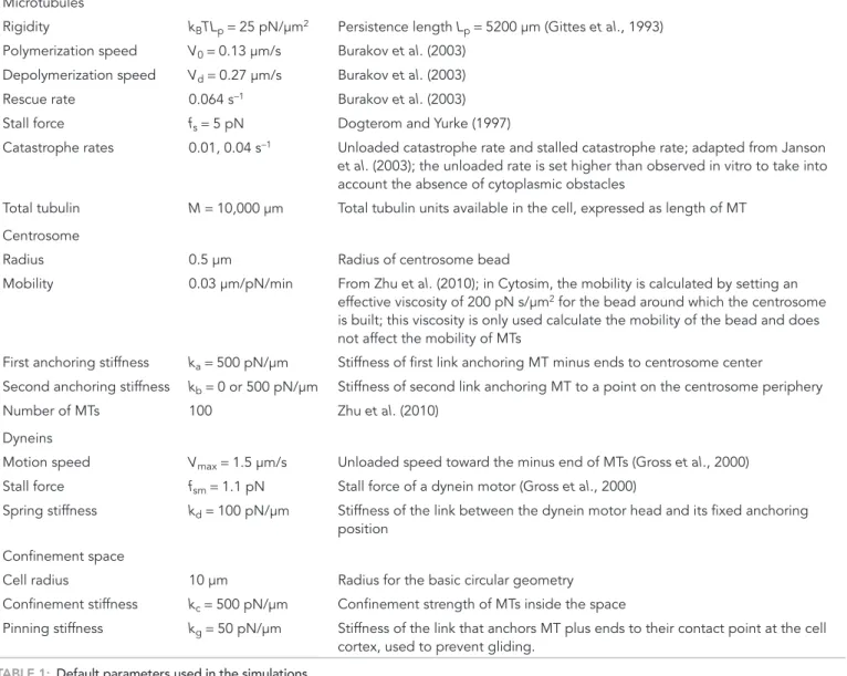
Parameter Description/reference
Microtubules
Rigidity kBTLp = 25 pN/μm2 Persistence length L
p = 5200 μm (Gittes et al., 1993)
Polymerization speed V0 = 0.13 μm/s Burakov et al. (2003)
Depolymerization speed Vd = 0.27 μm/s Burakov et al. (2003)
Rescue rate 0.064 s−1 Burakov et al. (2003)
Stall force fs = 5 pN Dogterom and Yurke (1997)
Catastrophe rates 0.01, 0.04 s−1 Unloaded catastrophe rate and stalled catastrophe rate; adapted from Janson
et al. (2003); the unloaded rate is set higher than observed in vitro to take into
account the absence of cytoplasmic obstacles
Total tubulin M = 10,000 μm Total tubulin units available in the cell, expressed as length of MT Centrosome
Radius 0.5 μm Radius of centrosome bead
Mobility 0.03 μm/pN/min From Zhu et al. (2010); in Cytosim, the mobility is calculated by setting an effective viscosity of 200 pN s/μm2 for the bead around which the centrosome
is built; this viscosity is only used calculate the mobility of the bead and does not affect the mobility of MTs
First anchoring stiffness ka = 500 pN/μm Stiffness of first link anchoring MT minus ends to centrosome center
Second anchoring stiffness kb = 0 or 500 pN/μm Stiffness of second link anchoring MT to a point on the centrosome periphery
Number of MTs 100 Zhu et al. (2010)
Dyneins
Motion speed Vmax = 1.5 μm/s Unloaded speed toward the minus end of MTs (Gross et al., 2000)
Stall force fsm = 1.1 pN Stall force of a dynein motor (Gross et al., 2000)
Spring stiffness kd = 100 pN/μm Stiffness of the link between the dynein motor head and its fixed anchoring
position Confinement space
Cell radius 10 μm Radius for the basic circular geometry Confinement stiffness kc = 500 pN/μm Confinement strength of MTs inside the space
Pinning stiffness kg = 50 pN/μm Stiffness of the link that anchors MT plus ends to their contact point at the cell cortex, used to prevent gliding.
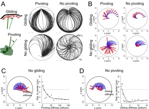
work symmetry and place the centrosome near the cell periphery (Figure 3, B and C). Of interest, these behaviors were independent of centrosome initial position (Figure 3B), meaning that if the centrosome is initially po-sitioned at the cell center, the symmetry in the network will be spontaneously broken because of MT pivot, glide, or both, leading to centrosome decentering.
We then studied how MT stiffness, num-ber, and length affected these behaviors. In the symmetric conformations of the net-work, when both MT gliding and pivoting were restricted, centering appeared robust with respect to a decrease in MT number and length (Supplemental Figure S4 and Supplemental Movie S5). The effects of changing MT stiffness were mild, between 20 and 100 pN/μm2. Very soft MTs could
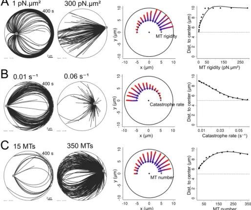
not transmit polymerization forces effi-ciently, whereas very rigid MTs could not bend after reaching the cortex, in both cases freezing the centrosome motion (Supplemental Figure S4). If the MT net-work lost its isotropy, either because MT gliding along edges or pivoting around the base was allowed, then increasing the number of MTs progressively reinforced the net pushing forces and decentered the centrosome (Figure 4 and Supplemental Movie S4). We observed this effect by ei-ther raising the number of nucleation sites or decreasing the catastrophe rate. Increas-ing the stiffness of MTs also produced the same outcome. All of these parameters are therefore interesting targets if one wants to induce centrosome decentering.
Transitions from centering to decentering regimes
We then combined the pulling forces due to minus end–directed motors and the pushing forces due to MT polymerization to investi-gate the potential transition from centering to decentering regimes. Because dynein inhibition has been shown to induce centrosome decentering (Burakov et al., 2003; Wu et al., 2011), we assumed that dynein-associated forces contributed to center the centrosome, that is, that dynein molecules are anchored in the cytoplasm rather than at the cell cortex. We first wanted to know whether a centrosome could spontaneously move off center in the absence of asymmetric cues. We thus tested whether a global variation of the MT network properties, such as the parameters described here, could overcome the centering effect of cytoplasmic dyneins and promote centro-some displacement to a peripheral position.
As found in the first part of this study, with a high concentration of cytoplasmic dyneins (4000 dyneins per cell, corresponding to 40 per MT), MT outward-pushing forces were not sufficient to over-come the dynein-induced centering effect (Figures 1 and 2). Transi-tions were seen only in cells in which the dynein concentration was reduced. In the following simulations, we used 100 dyneins per cell (i.e., 1 per MT). This condition is physiologically relevant because it has been shown that pushing and pulling forces are of comparable magnitude (Zhu et al., 2010). We thus studied the conditions in which variations in MT rigidity, number, and catastrophe rate, as well observation in lymphoblastic cell lines (Bornens et al., 1989) and
pre-vious numerical simulations (Pinot et al., 2009), when both pivoting and gliding were allowed, the network became asymmetric and pushed the centrosome off-center toward the closest edge (Figure 3A, top left). Indeed, MTs oriented toward the closest side were the first to reach the cortex and glide toward the opposite direction to minimize the bending energy associated with their curvature. This effect was reduced if MT pivoting was forbidden, as the aster re-mained more isotropic (Figure 3A, top right). Strikingly, when MT glid-ing along the cell cortex was prevented, those first MTs in contact with the cell cortex were pinned and pushed on the centrosome, which was displaced toward the opposite cell edge (Figure 3A, bot-tom left). MT pivoting ability allowed them to join and form comet-like tail pushing the centrosome, as observed in Dictyostelium (Brito
et al., 2005). Of interest, when both gliding and pivoting were
pre-vented, the network never became asymmetric. Instead, it rotated briefly and adopted a vortex-shaped conformation in which the push-ing forces kept the centrosome near the cell center (Figure 3A, bot-tom right). This centering effect by symmetric pushing forces was quite robust and independent of cell geometry (Supplemental Figure S3). As we reduced the strength of either the pivoting or the gliding stiffness while fixing the other, the network displayed rapid transition from centering to decentering (Figure 3C). This suggested that the modulation of these parameters can be an efficient way to break
net-FIGURE 1: Centrosome centering by pulling forces. (A) Simulation in which the motors are distributed in the cell. (B) Simulation in which the motors are distributed only on the edge the cell. Dynein motors are shown in green and MTs in black. Right, centrosome positions, indicated by colored points, from blue (0 s) to red (400 s). Left, centrosome trajectories. The gray area is the area filled by motors. (C) Variation of the number of motors for both cytoplasmic and cortical motor distribution. Fifteen trajectories are shown on each plot, in which the number of
simulated dyneins is increased from 0 to 7000 with a step of 500. The initial position of the centrosomes was set on an arc axis to make them all visible on a single plot. This should not affect the outcome of the simulation, since the system has rotational symmetry. In all cases, the centrosomes are initially placed at a distance from the center corresponding to half the cell radius. Right, maximal speed reached by the centrosome during each simulation as a function of the number of dyneins for both cortical and cytoplasmic distributions. Each symbol is the result of one simulation, and the lines are guides for the eye.
the pushing forces are stronger (because they scale as 1/L2 according to Euler’s theory;
Figure 5, B and C, and Supplemental Movie S6). Reducing drastically the catastrophe rate turned the centering regime into a weak de-centering one (Figure 5B). The system was quite sensitive to the number of MTs, and a progressive transition from centering to de-centering occurred as the number of MTs in-creased (Figure 5C). Varying either centro-some angular stiffness (which affected pivoting) or cortex anchor stiffness (which af-fected sliding) had even more drastic effects and could induce abrupt transitions in the position of the centrosome (Figure 5, D and E, and Supplemental Movie S6). From these results, the ability of the network to reorga-nize asymmetrically appears as a key regula-tor of the force balance at the centrosome.
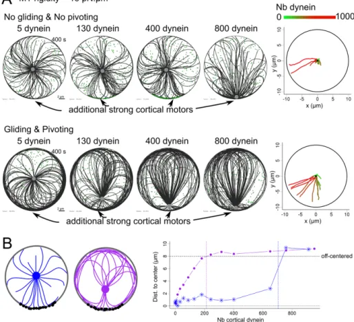
Of note, these results showed that mod-erate changes in any of the tested parame-ters, isolated or in parallel, were often suffi-cient to induce a complete reversal of whether the centrosome is located at the center or near the periphery of the cell. In the case in which the transition is not com-plete, a parameter change could prime the network for such a transition. For example, allowing the network to be asymmetric in-creased the net force on the centrosome. Even when this force was effectively bal-anced by the inward-pulling forces exerted by cytoplasmic dynein, it made the reversal more likely to occur if another perturbation was added. For example, the net inward-pulling force can be further reduced by ad-ditional asymmetric outward-pulling forces, such as those exerted along cell–cell con-tacts. This idea was tested by adding exter-nal cues, which were simulated by adding cortical dyneins within a 60°-wide crescent. We then compared the response of a “con-strained” network, in which MT central piv-oting and peripheral gliding were forbid-den, and the response of a “reconfigurable” network in which pivoting and gliding are allowed, to increasing amounts of localized cortical dyneins (Figure 6A). The constrained network was less sensitive to asymmetric pulling forces, since the pushing from the captured MTs opposed the tension devel-oped by the cortical dyneins (Figure 6A and Supplemental Movie S7). By contrast, the reorientation of MTs in the “reconfigurable” network redirected some polymerization forces toward the cortical pulling site (Figure 6B and Supplemental Movie S7). Thus the “re-configurable” network appeared more responsive to external cues, and the centrosome decentered more readily (Figure 6C). Together these results indicate that several intrinsic parameters of the MT net-works, such as MT number, rigidity, and in particular the ability to reorient MTs, is key to modulating the response of the cell. The mag-nitude and distribution of pushing forces could either lead to robust centering of the centrosome or place it in a reactive conformation, as centrosome pivoting and cortex gliding stiffness, could lead to
decentering despite the dynein-induced centering pulling forces. As MT rigidity was increased, the net force applied on the centro-some progressively switched from centering to decentering (Figure 5A and Supplemental Movie S6). However, variations of catastrophe rate and number of MTs, although able to increase the magnitude of pushing forces (Figure 4), did not cause decentering (unpublished data). This is due to the magnitude of the forces applied to MTs tips, which are such that they induce catastrophe events and thus limit the efficiency of the pushing force. However, transitions from centering to decentering were observed in smaller cells (of radius 7 μm), in which
FIGURE 2: Centrosome positioning by pulling forces. (A, B) Top, snapshot after 400 s of a centrosome simulated in different geometries: ellipse, rectangle, equilateral triangle, acute isosceles triangles, and isosceles triangle whose base is the longest side. Dyneins are shown in green, MTs in black, and the centrosome in gray. Motors are distributed (A) cytoplasmically or (B) cortically. Bottom, trajectories of centrosomes in 15 simulations for each geometry. Centrosome position is indicated by colored points, from blue (0 s) to red (400 s), in the trajectory plots. The gray area is the area covered by motors. Black dot indicates the center of gravity of the shape. (C) Left, box plot of the distance of the centrosome to the center of gravity after 400 s for each geometry for cytoplasmic and cortical distributions (full and empty boxes, respectively). Right, strip chart of the final speed of the centrosome in the simulations for all geometries for cytoplasmic and cortical distributions (full and empty triangles, respectively).
of cytoplasmic and cortical dyneins. We con-firmed that cytoplasmic dynein molecules in-duce robust centrosome centering, whereas cortically anchored dyneins are capable of promoting either centering or decentering, depending on cell shape (Ma et al., 2014). Asymmetric pulling forces due to cell shape extension promoted centrosome decenter-ing toward the longest cell edge.
Next we studied how the MT network configuration determined the orientations of pushing forces associated with MT polymer-ization. When MTs are tightly constrained in space, that is, if they cannot pivot around their anchor point in the centrosome and if their plus ends cannot glide along the cell edge, they maintain an isotropic distribution and generate centering forces. In contrast, when the MTs are free to pivot or slide, the net pushing force pushes the centrosome to-ward the periphery. In both scenarios, MT stiffness and number can modulate the speed at which the centrosome moves. Thus, when pushing forces are opposed by dynein-induced pulling forces, modifying the num-ber of MTs or their stiffness could trigger a transition from a regime in which the centro-some is at the center to a regime in which the centrosome adopts a peripheral position.
We investigated some theoretical mech-anisms that can affect MT architecture and centrosome positioning, limiting our ap-proach to numerical experiments. The re-sults pointed to the possible role of several parameters, suggesting possible experimen-tal investigations.
Centrosome angular anchor stiffness ap-peared as a critical parameter, since small variations from 20 to 5 pN/μm were sufficient to induce an abrupt transition from a center-ing to a decentercenter-ing regime (Figure 5E). The anchorcenter-ing of MTs at the centrosome is not well characterized. MTs can detach from the centro-some in mammalian cells (Keating and Borisy, 1999; Alieva et al., 2015) and were seen to pivot around yeast mitotic spindle poles (Kalinina et al., 2012), but the angular stiffness has not been measured. The pivoting of a MT with respect to the centrosome is likely to de-pend primarily on the stiffness of the pericentriolar material in which MTs are embedded. Regulation of pericentriolar material density and cross-linking density (Woodruff et al., 2014), as well as the polymeriza-tion of actin filaments nearby (Farina et al., 2016), could possibly affect this stiffness. Moreover, the ability of MTs under tension to tear apart pieces of pericentriolar material during specific phases of the cell cycle suggests that the material stiffness is precisely regulated (Megraw
et al., 2002; Rusan and Wadsworth, 2005; Krueger et al., 2010).
Pushing forces naturally scale in proportion with the number of MTs in the aster and inversely with the squared length of the MT, but these parameters also have a less obvious effect on the network symmetry (Figure 4). They vary widely from one cell type to another and also during cell cycle progression (Piehl et al., 2004). It would be interesting to look at them in more detail during centering-to-de-centering transitions—for instance, during epithelial morphogene-sis, ciliogenemorphogene-sis, or immune synapse formation.
where it could respond to weaker external asymmetric stimulation. Such reactive conformations are characterized by spontaneous sym-metry-breaking events and centrosome decentering in the absence of asymmetric external cues.
DISCUSSION
The process of centrosome positioning is still under investigation, in particular because different mechanisms can prevail in different cel-lular conditions (Ma et al., 2014). Here we focused on conditions in which MTs can be longer than the cell diameter, which is the case for adult mammalian cells in interphase (Wu et al., 2011), rather than the more usually studied large mitotic cells in embryos (Kimura and Onami, 2007; Wühr et al., 2010; Minc et al., 2011). Under these con-ditions, several parameters could regulate the symmetry of MT net-work architecture, independently of external cues or preexisting asymmetries in boundary conditions such as local capture, stabiliza-tion, or mechanical forces. MT number, length, and rigidity, as well as centrosome stiffness, all have the ability to induce a spontaneous network symmetry break and thus lead to centrosome decentering.
Centering capacities are generally considered to result from minus end–directed motors such as dyneins (Kimura and Kimura, 2011b). Here, by using numerical simulations, we compared the contributions
FIGURE 3: MT network rearrangement in the presence of pushing forces. (A) Left, schematic representation of a MT plus end gliding at the cortex and a MT pivoting around its anchor point in the centrosome. MTs and centrosomal complex are in green, actin cortex in red. Right, snapshots of simulations (400 s) covering all the possibilities when pivoting and gliding are independently allowed or not. (B) Trajectories of centrosomes in 15 simulations in which the centrosome was initially positioned at different distances from the cell center and for each of the pivoting/gliding conditions. The center of each disk is marked with a black point. (C) Left, trajectories of centrosomes in simulations with varied pivoting stiffness when gliding is not allowed. Pivoting stiffness is varied geometrically from 0 to 150 pN/μm from left to right along the arc. Right, centrosome positioning as a function of pivoting stiffness, measured by the distance to the cell center. The dashed line indicates the initial centrosome–center distance. (D) Left, trajectories of the centrosome in simulations with varying gliding stiffness when pivoting is not allowed. Gliding stiffness is varied geometrically from 0 to 15.5 pN/μm from left to right along the arc. Right, centrosome positioning as a function of gliding stiffness, measured by the distance to the cell center. The dotted line indicates the initial centrosome–center distance. In all of the plots, the color of the centrosome trajectories indicates time, from blue (0 s) to red (400 s).
result in MT network rearrangement and in-duce centrosome repositioning.
For the sake of simplicity, several factors were not taken into account in our simula-tions, notably the contribution of noncentro-somal MTs (Alieva et al., 2015) and kinesins (Cross and McAinsh, 2014), although we know that these factors contribute to the in-trinsic regulation of force production and network reorganization. We also ignored key external contributions, such as centro-some and MT interactions with the nucleus (Burakov and Nadezhdina, 2013) and the production of forces by the actin cytoskele-ton (Waterman-Storer and Salmon, 1997; Gupton et al., 2002). Also of importance, we considered that the cytoplasm was devoid of obstacles and that MT motions were hin-dered only by cell boundaries. The elasticity of the actin network and other obstacles sur-rounding MTs might, however, constrain their deformation and significantly increase the magnitude of pushing forces transmit-ted to the centrosome (Brangwynne et al., 2006; Shan et al., 2012). These important parameters deserve further investigation.
In this work, we studied the ability of MT asters to become anisotropic, a reorganiza-tion of the MT network that ultimately pushed the centrosome near the cell periphery. In physiological conditions, the MT cytoskele-ton within a cell is rarely isolated, as cells con-tact other cells. These concon-tacts represent ex-ternal cues that affect the MT network within each cell. A MT network spanning the entire cytoplasm can physically integrate all these contributions from the surrounding tissue. Ul-timately, the position of the centrosome thus results from the spatial integration of all of the peripheral cues, either filtered or amplified, depending on the intrinsic properties of the MT network.
MATERIALS AND METHODS
All simulations were performed using Cytosim (www.cytosim.org). The values of the main parameters are presented in Table 1. The motion of elastic fibers surrounded by a viscous fluid (we used a viscosity of 1 pN s/μm2; Kole et al., 2005) was calculated using
Lan-gevin dynamics (Nedelec and Foethke, 2007). Microtubules were thus subject to Brownian motion as determined by their size and temperature (kBT = 4.2 pN⋅nm).
Microtubule dynamics
MT minus ends are stably anchored to the centrosome. Plus ends undergo dynamic instability (Mitchison and Kirschner, 1984) follow-ing a two-state model. Each state is implemented in Cytosim as follows:
• Polymerization occurs with a speed Vg that is proportional to the free tubulin pool in the cell and decreases exponentially under opposing force as measured (Dogterom and Yurke, 1997):
Vg= αV0 exp(−f f/ )s
Our simulations confirmed a strong role for MT stiffness, which was expected since MT bending stiffness is a key param-eter in the transmission of MT polymerization force produced at the plus ends to the centrosome attached at the minus ends and thereby regulates the net force on the centrosome. Increasing the MT stiffness is sufficient to switch from a centering to a de-centering regime (Figure 5A). Several parameters have been shown to affect MT rigidity (Hawkins et al., 2010). MT-associated proteins can either increase (Felgner et al., 1997) or decrease (Portran et al., 2013) MT bending stiffness. MT cross-linking molecules can also modulate the size of MT bundles and conse-quently their rigidity (Bathe et al., 2008) and thus affect the system similarly.
Cortical stiffness in our simulations reflects the interaction that MTs have with the cell cortex and is a property of the cell cortex. MT ability to glide or not along cell cortex was key to network rearrange-ment, symmetry breaking, and the orientation of pushing forces to-ward the cell periphery (Figures 3 and 5D). This parameter reflects the fact that MTs could get entangled in a crowded cortical actin network or be physically linked to those microfilaments (Coles and Bradke, 2015). Plus ends have been seen to grow or not along the cell periph-ery, depending on the presence of filament bundles or branched meshwork, suggesting that the local actin architecture could regulate MT gliding (Théry et al., 2006). Accordingly, changes in cell adhesion and modifications of the associated cortical actin network could
FIGURE 4: Efficiency of pushing forces with pivoting and gliding allowed. (A–C) Simulations in which one parameter was geometrically varied: MT rigidity, from 1 to 300 pN/μm2; MT unloaded
catastrophe rate, from 0.01 to 0.06 s−1; and number of MTs in the aster, from 15 to 350. Left,
two exemplary simulations (400 s) obtained by varying one parameter in each case. Middle, trajectories of centrosomes obtained by varying one parameter, displayed along an arc, with increasing values from left to right. For each trajectory, time is indicated by the color, from blue (0 s) to red (400 s). The center of each disk is marked with a black dot. Right, centrosome positioning as a function of various parameters, measured by the distance to the cell center. The dotted lines represent the initial centrosome–center distance (half of the confinement radius).
where f is the force component parallel to the axis of the MT, fs is the stall force, V0 is the growth speed parameter, and α is a di-mensionless factor of range [0, 1] represent-ing the fraction of monomer available in the cell. This factor is calculated from the sum of all MT lengths in the cell divided by the total available tubulin pool, expressed in units of MT length:
L M
1
∑
i α = −• Depolymerization occurs at a constant speed, Vd.
• Catastrophe events occur with a rate, τc,
that depends on the growth speed of the fiber: V V / 1 1 c stall stall 0 g 0 τ = τ +ττ −
where τstall is the rate of catastrophe of a
stalled microtubules, which is greater than the rate of catastrophe of a free microtu-bule, τ0 (Janson et al., 2003).
• Rescue events occur at a constant rate, τr.
Microtubule bending elasticity
Microtubules are modeled as semiflexible polymers (Nedelec and Foethke, 2007), and their buckling thus follows Euler’s law. If the loading is slow, buckling occurs in the first mode, at a threshold of force given by, for a length L and a persistence length Lp,
f k TL L b 2 B P 2 =π Centrosome
The centrosome is simulated as an aster with a fixed number of microtubules. All MTs are attached to a small bead of radius R whose mobility (i.e., inverse of the drag co-efficient) is chosen to match the value of the mobility calculated for the centrosome in Zhu et al. (2010) to take into account centro-some motion velocities experimentally mea-sured in Burakov et al. (2003). The microtu-bules are anchored at the center of the aster with two Hookean links. The first link, of stiff-ness ka, attaches the minus end of the MTs with the center of the bead. The second link, of stiffness kb, attaches a distal point on the surface of the bead with the point of the MT that is located at distance R from the mi-nus end. The number of distal points on the bead is equal to the number of MTs in the
FIGURE 5: Transitions between centering and decentering regimes. (A–E) Simulations in which one parameter was geometrically varied: MT rigidity, from 1 to 260 pN/μm2; MT
unloaded catastrophe rate, from 0.01–0.06 s−1; number of MTs, from 15 to 350; MT gliding
stiffness while pivoting is not allowed, from 0 to 10 pN/μm; and MT pivoting stiffness when gliding is not allowed, from 0 to 110 pN/μm. In each case, 100 cytoplasmic dynein motors were randomly positioned in the cell and one parameter of the system was varied
systematically. Cell radius is 10 μm in A and 7 μm in B–E. Left, exemplary simulations for two different outcomes observed while varying a parameter. Middle, trajectories of simulations obtained while varying a parameter, displayed along an arc, with values increasing from left to right. For each trajectory, time is indicated by the color, from blue (0 s) to red (400 s). The center of each disk is marked with a black dot. Right, centrosome positioning as a function of various parameters, measured by the distance to the cell center. The dotted line represents the initial centrosome–center distance (half of the confinement radius). In A–C, MTs were allowed to pivot and glide.
a force that is always orthogonal to the edge, thus corresponding to a perfectly slippery edge on which MTs can slide freely. However, in some simulations, the plus end of a MT reaching the edge of the geometry was “pinned” by a spring of stiffness kg act-ing between the microtubule plus end and the point at which the plus end first reached the edge. When this constraint is added, gliding of microtubules along the cortex is strongly impaired, and the impediment de-pends on kg. It is interesting to note that we chose to implement cortical friction as a pinning system rather than a local friction term for simplicity. Both friction modes could be envisaged, as they might depend on cell conditions, as noted in the
Discus-sion (adherent or nonadherent cells, cell in
tissue or isolated, cell wall presence or not, etc.). It would be interesting to compare the effects of both frictional constraints in future studies.
Motors
A dynein molecule is simulated as a point-like object that can bind and unbind to mi-crotubules linked to a fixed position by a spring of stiffness kd. This spring represents the anchorage of dyneins either at the cor-tex or on some vesicle in the cytoplasm. The dynein head moves on a fiber with a speed that depends on the load experienced by the spring: V V f f 1 max sm = −
where Vmax is the speed of a motor without
load and fsm is the motor stall force. The value of Vmax used here is negative,
repre-senting the fact that the dynein head moves toward the minus end of the microtubule. Strong cortical motors
Strong cortical motors were added to the simulation to represent the possible effect of local motors associated with proteins such as Par3 in the corti-cal environment. The particularity of these motors is that they do not unbind unless the microtubule is shrinking. Moreover, these motors stabilize MTs. Specifically, when one or more motors is bound within 0.5 μm of a plus end, the catastrophe rate of this MT plus end is temporarily set to zero, such that it continues to grow. The other parameters describing the motor (speed, stall force, spring stiffness, etc.) are kept equal to those of classic motors.
Analysis
Analysis graphics were generated with open source R software. The general tendency of distance to center evolution was fitted with a spline curve of degree four to six according to the smoothness of the data (using the smooth.spline R function) and is shown as a solid black line in the graphics.
aster, and they are distributed regularly around the center of the bead, such as to induce an isotropic aster. To allow MTs to pivot, kb is set to 0. In this case, MTs are constrained by only one link and can freely pivot while their minus ends remain attached to the center of the bead.
Confinement
To model the effect of the cortex of the cell on microtubules, the fi-bers are confined within a fixed geometry. A Hookean force is ap-plied to every microtubule model point that is located outside the confinement geometry:
fc=k p xc[ ( )−x]
where kc is the spring stiffness and p(x) is the projection of the model point x on the edge of the confinement space. This creates
FIGURE 6: Sensitivity of centrosome positioning to external cues, modulated by internal properties. (A, B) The centrosome is initially placed in the center of the cell and is decentered. The cell has a radius of 10 μm and contains 300 randomly positioned cytoplasmic dyneins. MT rigidity is set to 15 pN/μm2. (A) Simulations in which MT pivoting and gliding are not allowed
(top) and MT pivoting and gliding are allowed (bottom). Left, simulations (400 s) in which different numbers (5, 130, 400, and 800) of cortical dynein have been added on a 60° crescent at the bottom part of the cell. Right, trajectories of centrosomes, in a color representing the number of dyneins in the cell from 0 (green) to 1000 (red). The position of the cortical crescent was shifted to make it possible to distinguish the different trajectories on a single plot. (B) Left, schematic representation of MT network configuration when MT pivoting and gliding are not allowed (blue) and when both are allowed (purple). Cortical dynein molecules are represented in black. Right, final distance of centrosome to cell center according to the number of cortical dyneins placed on the crescent when gliding and pivoting are not allowed (blue) and allowed (purple). The black horizontal dashed line indicates the threshold above which we considered the centrosome to be off center. Colored vertical dashed lines represent threshold number of motors necessary to be decentered in each case.
ACKNOWLEDGMENTS
This work was supported by the European Research Commission (Starting Grant 310472), the Agence Nationale de la Recherche (ANR-12-BSV5-0014-02), the Labex Grenoble Alliance for Integrated Structural Cell Biology, and a Contrat de These sur Budget Unite (CTBU) Grant from the Commissariat à l’Energie Atomique to G.L.
REFERENCES
Alieva IB, Berezinskaya T, Borisy GG, Vorobjev IA (2015). Centrosome nucle-ates numerous ephemeral microtubules and only few of them partici-pate in the radial array. Cell Biol Int 39, 1203–1216.
Bathe M, Heussinger C, Claessens MMAE, Bausch AR, Frey E (2008). Cyto-skeletal bundle mechanics. Biophys J 94, 2955–2964.
Bornens M, Paintrand M, Celati C (1989). The cortical microfilament system of lymphoblasts displays a periodic oscillatory activity in the absence of microtubules: implications for cell polarity. J Cell Biol 109, 1071–1083.
Brangwynne CP, MacKintosh FC, Kumar S, Geisse NA, Talbot J, Mahade-van L, Parker KK, Ingber DE, Weitz DA (2006). Microtubules can bear enhanced compressive loads in living cells because of lateral reinforce-ment. J Cell Biol 173, 733–741.
Brito DA, Strauss J, Magidson V, Tikhonenko I, Khodjakov A, Koonce MP (2005). Pushing forces drive the comet-like motility of microtubule arrays in Dictyostelium. Mol Biol Cell 16, 3334–3340.
Burakov A, Nadezhdina E, Slepchenko B, Rodionov V (2003). Centrosome positioning in interphase cells. J Cell Biol 162, 963–969.
Burakov AV, Nadezhdina ES (2013). Association of nucleus and centrosome: magnet or velcro? Cell Biol Int 37, 95–104.
Coles CH, Bradke F (2015). Coordinating neuronal actin–microtubule dy-namics. Curr Biol 25, R677–R691.
Combs J, Kim SJ, Tan S, Ligon LA, Holzbaur EL, Kuhn J, Poenie M (2006). Recruitment of dynein to the Jurkat immunological synapse. Proc Natl Acad Sci USA 103, 14883–14888.
Cross RA, McAinsh A (2014). Prime movers: the mechanochemistry of mitotic kinesins. Nat Rev Mol Cell Biol 15, 257–271.
Dogterom M, Yurke B (1997). Measurement of the force-velocity relation for growing microtubules. Science 278, 856–860.
Dupin I, Camand E, Etienne-Manneville S (2009). Classical cadherins control nucleus and centrosome position and cell polarity. J Cell Biol 185, 779–786.
Faivre-Moskalenko C, Dogterom M (2002). Dynamics of microtubule asters in microfabricated chambers: the role of catastrophes. Proc Natl Acad Sci USA 99, 16788–16793.
Farina F, Gaillard J, Couté Y, Guérin C, Sillibourne J, Blanchoin L, Théry M (2016). The centrosome is an actin-organizing center. Nat Cell Biol 18, 65–75 .
Felgner H, Frank R, Biernat J, Mandelkow EM, Mandelkow E, Ludin B, Matus A, Schliwa M (1997). Domains of neuronal microtubule-associated proteins and flexural rigidity of microtubules. J Cell Biol 138, 1067– 1075.
Garzon-Coral C, Fantana HA, Howard J (2016). A force-generating machin-ery maintains the spindle at the cell center during mitosis. Science 352, 1124–1127.
Gittes F, Mickey B, Nettleton J, Howard J (1993). Flexural rigidity of micro-tubules and actin filaments measured from thermal fluctuations in shape. J Cell Biol 120, 923–934.
Gomes ER, Jani S, Gundersen GG (2005). Nuclear movement regulated by Cdc42, MRCK, myosin, and actin flow establishes MTOC polarization in migrating cells. Cell 121, 451–463.
Grill SW, Go P, Hyman AA (2001). Polarity controls forces governing asym-metric spindle positioning in the Caenorhabditis elegans embryo. Nature 409, 630–633.
Gross SP, Welte MA, Block SM, Wieschaus EF (2000). Dynein-mediated cargo transport in vivo: A switch controls travel distance. J Cell Biol 148, 945–955.
Gupton SL, Salmon WC, Waterman-Storer CM (2002). Converging popu-lations of f-actin promote breakage of associated microtubules to spatially regulate microtubule turnover in migrating cells. Curr Biol 12, 1891–1899.
Hale CM, Chen W-C, Khatau SB, Daniels BR, Lee JSH, Wirtz D (2011). SMRT analysis of MTOC and nuclear positioning reveals the role of EB1 and LIC1 in single-cell polarization. J Cell Sci 124, 4267–4285.
Hawkins T, Mirigian M, Selcuk Yasar M, Ross JL (2010). Mechanics of micro-tubules. J Biomech 43, 23–30.
Holy TE, Dogterom M, Yurke B, Leibler S (1997). Assembly and positioning of microtubule asters in microfabricated chambers. Proc Natl Acad Sci USA 94, 6228–6231.
Janson ME, de Dood ME, Dogterom M (2003). Dynamic instability of micro-tubules is regulated by force. J Cell Biol 161, 1029–1034.
Kalinina I, Nandi A, Delivani P, Chacón MR, Klemm AH, Ramunno-Johnson D, Krull A, Lindner B, Pavin N, Tolic’-Nørrelykke IM (2012). Pivoting of microtubules around the spindle pole accelerates kinetochore capture. Nat Cell Biol 14, 1–8.
Keating TJ, Borisy GG (1999). Centrosomal and non-centrosomal microtu-bules. Biol Cell 91, 321–329.
Kimura A, Onami S (2007). Local cortical pulling-force repression switches centrosomal centration and posterior displacement in C. elegans. J Cell Biol 179, 1347–1354.
Kimura K, Kimura A (2011a). Intracellular organelles mediate cytoplasmic pulling force for centrosome centration in the Caenorhabditis elegans early embryo. Proc Natl Acad Sci USA 108, 137–142.
Kimura K, Kimura A (2011b). A novel mechanism of microtubule length-dependent force to pull centrosomes toward the cell center. Bioarchitec-ture 1, 74–79.
Kole TP, Tseng Y, Jiang I, Katz JL, Wirtz D (2005). Intracellular mechanics of migrating fibroblasts. Mol Biol Cell 16, 328–338.
Kozlowski C, Srayko M, Nedelec F (2007). Cortical microtubule contacts position the spindle in C. elegans embryos. Cell 129, 499–510. Krueger LE, Wu JC, Tsou MFB, Rose LS (2010). LET-99 inhibits lateral
pos-terior pulling forces during asymmetric spindle elongation in C. elegans embryos. J Cell Biol 189, 481–495.
Laan L, Pavin N, Husson J, Romet-Lemonne G, van Duijn M, López MP, Vale RD, Jülicher F, Reck-Peterson SL, Dogterom M (2012a). Cortical dynein controls microtubule dynamics to generate pulling forces that position microtubule asters. Cell 148, 502–514.
Laan L, Roth S, Dogterom M (2012b). End-on microtubule-dynein interac-tions and pulling-based positioning of microtubule organizing centers. Cell Cycle 11, 3750–3757.
Loughlin R, Heald R, Nedelec F (2010). A computational model predicts Xenopus meiotic spindle organization. J Cell Biol 191, 1239–1249. Loughlin R, Wilbur JD, McNally FJ, Nedelec F, Heald R (2011). Katanin
contributes to interspecies spindle length scaling in Xenopus. Cell 147, 1397–1407.
Ma R, Laan L, Dogterom M, Pavin N, Jülicher F (2014). General theory for the mechanics of confined microtubule asters. New J Phys 16, 013018.
Maly VI, Maly IV (2010). Symmetry, stability, and reversibility proper-ties of idealized confined microtubule cytoskeletons. Biophys J 99, 2831–2840.
Megraw TL, Kilaru S, Turner FR, Kaufman TC (2002). The centrosome is a dynamic structure that ejects PCM flares. J Cell Sci 115, 4707–4718. Minc N, Burgess D, Chang F (2011). Influence of cell geometry on
division-plane positioning. Cell 144, 414–426.
Mitchison T, Kirschner M (1984). Dynamic instability of microtubule growth. Nature 312, 237–242.
Nedelec F, Foethke D (2007). Collective Langevin dynamics of flexible cytoskeletal fibers. New J Phys 9, 427–427.
Nguyen-Ngoc T, Afshar K, Gönczy P (2007). Coupling of cortical dynein and G alpha proteins mediates spindle positioning in Caenorhabditis elegans. Nat Cell Biol 9, 1294–1302.
Pavin N, Laan L, Ma R, Dogterom M, Jülicher F (2012). Positioning of micro-tubule organizing centers by cortical pushing and pulling forces. New J Phys 14, 105025.
Piehl M, Tulu US, Wadsworth P, Cassimeris L (2004). Centrosome matura-tion: measurement of microtubule nucleation throughout the cell cycle by using GFP-tagged EB1. Proc Natl Acad Sci USA 101, 1584–1588. Pinot M, Chesnel F, Kubiak JZ, Arnal I, Nedelec FJ, Gueroui Z (2009). Effects
of confinement on the self-organization of microtubules and motors. Curr Biol 19, 954–960.
Portran D, Zoccoler M, Gaillard J, Stoppin-Mellet V, Neumann E, Arnal I, Martiel J-L, Vantard M (2013). MAP65/Ase1 promote microtubule flex-ibility. Mol Biol Cell 24, 1964–1973.
Reiter JF, Blacque OE, Leroux MR (2012). The base of the cilium: roles for transition fibres and the transition zone in ciliary formation, maintenance and compartmentalization. EMBO Rep 13, 608–618.
Rodriguez-Fraticelli AE, Auzan M, Alonso MA, Bornens M, Martin-Belmonte F (2012). Cell confinement controls centrosome positioning and lumen initiation during epithelial morphogenesis. J Cell Biol 198, 1011–1023.
Waterman-Storer CM, Salmon ED (1997). Actomyosin-based retrograde flow of microtubules in the lamella of migrating epithelial cells influ-ences microtubule dynamic instability and turnover and is associ-ated with microtubule breakage and treadmilling. J Cell Biol 139, 417–434.
Woodruff JB, Wueseke O, Hyman AA (2014). Pericentriolar material structure and dynamics. Philos Trans R Soc Lond B Biol Sci 369, 20130459.
Wu J, Misra G, Russell RJ, Ladd AJC, Lele TP, Dickinson RB (2011). Effects of dynein on microtubule mechanics and centrosome positioning. Mol Biol Cell 22, 4834–4841.
Wühr M, Tan ES, Parker SK, Detrich HW, Mitchison TJ (2010). A model for cleavage plane determination in early amphibian and fish embryos. Curr Biol 20, 2040–2045.
Yi J, Wu X, Chung AH, Chen JK, Kapoor TM, Hammer JA (2013). Centro-some repositioning in T cells is biphasic and driven by microtubule end-on capture-shrinkage. J Cell Biol 202, 779–792.
Zhu J, Burakov A, Rodionov V, Mogilner A (2010). Finding the cell center by a balance of dynein and myosin pulling and microtubule pushing: a computational study. Mol Biol Cell 21, 4418–4427.
Rusan NM, Wadsworth P (2005). Centrosome fragments and microtubules are transported asymmetrically away from division plane in anaphase. J Cell Biol 168, 21–28.
Shan WL, Chen Z, Broedersz CP, Gumaste AA, Soboyejo WO, Brangwynne CP (2012). Attenuated short wavelength buckling and force propagation in a biopolymer-reinforced rod. Soft Matter 9, 194–199.
Tang N, Marshall WF (2012). Centrosome positioning in vertebrate develop-ment. J Cell Sci 125, 4951–4961.
Théry M, Jiménez-Dalmaroni A, Racine V, Bornens M, Jülicher F (2007). Experimental and theoretical study of mitotic spindle orientation. Nature 447, 493–496.
Théry M, Racine V, Piel M, Pépin A, Dimitrov A, Chen Y, Sibarita J-B, Bornens M (2006). Anisotropy of cell adhesive microenvironment governs cell internal organization and orientation of polarity. Proc Natl Acad Sci USA 103, 19771–19776.
Tran PT, Marsh L, Doye V, Inoué S, Chang F (2001). A mechanism for nuclear positioning in fission yeast based on microtubule pushing. J Cell Biol 153, 397–411.
Ward JJ, Roque H, Antony C, Nedelec F (2014). Mechanical design prin-ciples of a mitotic spindle. Elife 3, 1–28.