DIGITAL MAKING
Exploring Design with Computer Controlled Fabrication
By Sameer Kashyap
Bachelor of Architecture (2001) Sushant School of Art and Architecture
Submitted to the Department of Architecture
In Partial Fulfillment of the Requirements for the Degree of Master of Science in Architecture Studies
Massachusetts Institute of Technology June 2004
C 2004 Sameer Kashyap. All rights Reserved
The author hereby grants to MIT permission to reproduce and to distribute publicly paper and electronic copies of this thesis in whole or part.
Signature of Author: Certified by: Certified by: Accepted by:
L/
Department of Architecture May 19, 2003 A1----William Lyman Porter
Norman B. and Muriel Leventhal Professor of Architycture and Plan/ng Thesis Adviso
Lawrence ass/
Assistant ro ssor of Architecture Thesis Advisor
Jul
Bei art
Profess6 f Architecture
Chair, Committee on Graduate Students
MASSACHUSETTS INS OF TECHNOL.OGY E
JUL
A
2004
Axel Kilian
Candidate of Doctor of Philosophy Department of Architecture, MIT Thesis Reader
Hugh Whitehead
Project Director for Research Foster and Partners, London Thesis Reader
DIGITAL MAKING
Exploring Design with Computer Controlled Fabrication
By Sameer Kashyap
Bachelor of Architecture (2001) Sushant School of Art and Architecture
Submitted to the Department of Architecture
In Partial Fulfillment of the Requirements for the Degree of Master of Science in Architecture Studies
Massachusetts Institute of Technology June 2004
Abstract
This thesis examines the underlying issues innate to the design process of developing architectural solutions using the digital for "making" architecture, focusing on architectural production. It proposes an alternative method for fabricating architecture that supports a fast, inexpensive design process using a combination of digital modeling (explicit or with generative methods) and computer controlled fabrication machines. A series of explorations and studies are conducted to establish a procedure for the integration of representational techniques and fabrication processes into methods for digital making. The thesis also suggests how computer-controlled fabrication can be integrated into design exploration, by embedding activities of digital making into the design process.
Supervisor: William Lyman Porter
Title: Norman B. and Muriel Leventhal Professor of Architecture and Planning
Supervisor: Lawrence Sass
Acknowledgements
I would like to thank God for giving me the courage to complete this thesis. I would also like to thank Bill Porter for his motivation, enthusiasm, and wisdom.
Larry Sass and Axel Killian have been pillars of support throughout the course of my research. I would like to thank them for their
guidance towards the completion of this thesis.
Hugh Whitehead for sharing with me his insights and experiences. He has been a mentor and a source of inspiration.
I also express much gratitude to my colleagues who have supported me over the past two years. Thank you, Stylianos, Carlos, Greg, David and Thomas.
Last but not the least; I would like to thank my family for believing in me.
Table of Contents
Table of Figures
Chapter 1 Introduction
Background Methodology 1.2.1 Digital Modeling1.2.2 Computer Controlled Fabrication Machines 1.2.3 Generative methods
1.2.4 Observations
Chapter 2
2.1
2.2
Explorations with Computer
Controlled Fabrication
Experiments in Digital Making
2.1.1 Approximating NURBS surfaces
2.1.2 Approximating surfaces with triangulation 2.1.3 Approximation of translational surfaces Experiment
Integrated Design and Manufacturing process Digital Design Fabrication Workshop
2.3.1 Context 2.3.2 Discussion
Chapter
3.1 3.2 3.3 3.4 3.53
Digital Making of Architecture
Production Strategies Design Rationalization
Parametrics, Generative methods and Automation Dimensional Tolerances
Chapter 4
Appendix
Glossary
Bibliography
Conclusions
Post script
Table of Figures
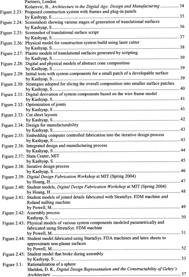
Figure 1.1: Zcorp 3D printer
Kolarevic, B., Architecture in the Digital Age; Design and Manufacturing ... 13 Figure 1.2: Roland milling machine
Kashyap, S... 13 Figure 1.3: Laser cutter:
Kashyap, S ... 13
Figure 1.4: StrataSys. FDM printer
Kashyap, S... 13
Figure 2.1: The shape of a NURBS curve can be changed by interactively manipulating the control points, weights and knots
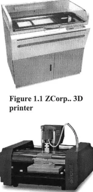
Kolarevic, B., Architecture in the Digital Age; Design and Manufacturing ... 18 Figure 2.2: Control lattice for a NURBS surface
Kolarevic, B., Architecture in the Digital Age; Design and Manufacturing ... 19 Figure 2.3: Isoparametric contours in the "U" direction of a NURBS surface
Kolarevic, B., Architecture in the Digital Age; Design and Manufacturing ... 19 Figure 2.4: Screenshots of NURBS surface representation showing isoparms and NURBS
surface representation showing rib members along isoparms
Kolarevic, B., Architecture in the Digital Age; Design and Manufacturing ... 19 Figure 2.5: Sketch diagram showing the proposed interlocking groove systems
by Dritsas, S... 20
Figure 2.6: Interlocking grooves generated by scripting procedures
by Dritsas, S... 20
Figure 2.7: Physical model of the NURBS surface
by Kashyap, S... 21
Figure 2.8: Cut sheet layout of ribs
by Kashyap, S... 21 Figure 2.9: Model showing rib components and assembled surface
by Kashyap, S ... 22
Figure 2.10: Variations
by Kashyap, S... 23
Figure 2.11: NURBS surface generated by contouring
by Kashyap, S ... 23
Figure 2.12: Great Court, British Museum, London
by Kashyap, S... 26
Figure 2.13: Coons Patches
McCullough, M., Mitchell, W. J., Digital Design Media ... 27
Figure 2.14: Proposed node-bar system for the approximated Coons patch surface
by Kashyap, S... 28
Figure 2.15: Screenshots showing generating of members using scripting procedures
by Kashyap, S... 28
Figure 2.16: Screenshots showing the generation of system components through scripting
by Kashyap, S... 29
Figure 2.17: Screenshot of cut sheet layout generated by scripting
by Kashyap, S... 31
Figure 2.18: Excel spreadsheet of clouds of points generated by scripting
by Kashyap, S... 31
Figure 2.19: Screenshots showing the mapping of a script to a wire frame
by Kashyap, S... 30
Figure 2.20: Images showing physical models and assembly process
by K ashyap, S. ... 3 1
Figure 2.2 1: Construction of a translation surface
Figure 2.22: Various projects constructed from translational surfaces, Architects Foster and Partners, London
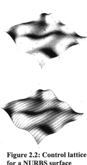
Kolarevic, B., Architecture in the Digital Age; Design and Manufacturing... 34 Figure 2.23: Proposed construction system with frames and plug-in panels
by Kashyap,S ... 3
Figure 2.24: Screenshots showing various stages of generation of translational surfaces
by Kashyap, S... 36
Figure 2.25: Screenshot of translational surface script
by Kashyap,S ... 3
Figure 2.26: Physical model for construction system build using laser cutter
by Kashyap, S... 38
Figure 2.27: Plaster models of translational surfaces generated by scripting
by Kashyap, S... 39
Figure 2.28: Digital and physical models of abstract cone composition
by Kashyap, S... 39
Figure 2.29: Initial tests with system components for a small patch of a developable surface
by Kashyap, S... 39
Figure 2.30: Strategies adopted for slicing the overall composition into smaller surface patches
by Kashyap, S..rchitecture.in.the.Dig... 40 Figure 2.31: Digital derivation of system components based on the wire frame model
by K ashyap , S ... .. ---... 41
Figure 2.32: Optimization ofjoints
by K ashyap, 5 ... .... ... 41
Figure 2.33: Cut sheet layouts
by Kashyap, S... ... ... 42 Figure 2.34: Design for manufacturability
by K ashyap, S... ... .... 3
Figure 2.35: Embedding computer controlled fabrication into the iterative design process
by K ashyap, S ... ... ---.... ---... 43 Figure 2.36: Integrated design and manufacturing process
by Kashyap, S... ... 44
Figure 2.37: Stata Center, MIT
by K ashyap, S... 45 Figure 2.38: Iterative design process
by K ashyap, S... 46
Figure 2.39: Digital Design Fabrication Workshop at MIT (Spring 2004)
by H oang, H ... ... .. ----... 47
Figure 2.40: Student models, Digital Design Fabrication Workshop at MIT (Spring 2004)
by Hoang, H... 48 Figure 2.41: Student models ofjoined details fabricated with StrataSys. FDM machine and
Roland milling machine
by Powell, M... 49 Figure 2.42: Assembly process
Kashyap, S ... 50 Figure 2.43: Physical models of various system components modeled parametrically and
fabricated using StrataSys. FDM machine
by Powell, M... 51 Figure 2.44: Student model fabricated using StartaSys. FDA machines and latex sheets to
approximate non-planar surfaces
by Powell, M... 52
Figure 2.45: Student model that broke during assembly
by Kashyap, S... 53
Figure 3.1: Rationalization of a sphere
Sheldon, D. R., Digital Design Representation and the Constructability of Gehry 's
Figure 3.2: Broken Plexiglas model due to tolerance failure
Chapter 1
Introduction
1.1 Background
Physical output from Rapid Prototyping and CAD/CAM machines represents a significant new method for visualization and fabrication of architecture. The possibility to directly realize tangible three-dimensional objects from computer models challenges traditional means of representation. These developments in the means of representation and fabrication require parallel changes in the architectural design process.
Representation and fabrication have always been inherent to the architectural design process'. Manipulation of material by hand leads to the creation of unique objects. Tools have developed as extensions of the hands, for example the chisel, saw, hand drill etc. As tools developed they became mechanized, such as the electric drill, but were still largely operated by hand. Up until now such tools have been sufficient for the design needs of buildings that were an outgrowth of the industrial revolution.
The computer as a tool could be thought of as an extension of the mind, similar to the hand-tool relation. As observed by Bill Mitchell, "Just as the industrial revolution replaced human muscle power by energy consuming machines, the computer revolution is replacing human brain power by information processing machines.""
To date, software for architecture and engineering has progressed from coarse drafting systems to highly sophisticated modeling and analysis tools. As we enter into the post-industrial-digital era, Computer Aided Design and Manufacturing (CAD/CAM) technologies make it possible to easily create and modify digital models and manipulate material through computer controlled movements to create physical three dimensional objects. This encourages repetition and variation that results in the making of distinct things. Furthermore, recent developments in the software industry allow designers to act as "creators of computational systems that can produce infinite possibilities and variations", extending the role of an architect to a "tool maker". The combination of these advances has profound implications on the architectural design process and production.
Today, both architectural practices and schools of architecture have started to incorporate cutting edge tools and equipment for computer controlled fabrication as an integral part of their facilities, challenging the potential of the digital for the "making" of architecture.
This thesis examines the underlying issues innate to the design process of developing architectural solutions using the digital for "making" architecture, with a focus on architectural production. It proposes an alternative method for fabricating architecture using a combination of digital modeling (both explicit and with generative methods) and rapid prototyping and CAD/CAM fabrication machines. The thesis also suggests how computer-controlled
fabrication can be integrated into design exploration by embedding activities of digital making into the design process.
The procedures outlined here are derived from experiences in three related contexts: 1. My personal explorations in the field of Digital Fabrication; 2. Involvement as a researcher with the Digital Design Fabrication Group and the Design Fabrication Workshop at the Massachusetts Institute of Technology (MIT); 3. Through, one-to-one discussion and analysis of various written materials by academicians and students in related fields.
1.2 Methods
1.2.1 Digital Modeling
Digital models are used to represent different aspects of design. This study is guided by an intention of directly translating 3-D digital models into material realization, with a focus on architectural production. Various digital modeling platforms are used including, AutoCAD (AutoDesk) Catia (Dassault Systems) and Rhinoceros (NURBS modeling software).
1.2.2 Computer Controlled Fabrication
Computer Controlled Fabrication enables us to translate three dimensional digital models into material realization. This is done by manipulating material with a machine that moves through computer controlled movements. These can be broken down into two broad groups: CAD/CAM fabrication machines (CNC machines) and Rapid Prototyping machines (RP machines). CNC machines use 2D
fabrication processes or subtractive fabrication processes of
manipulating materials to create objects. RP machines use additive
A 2Dfabrication process involves a two axis motion of cutting head relative to sheet material. For example, laser cutter, paper cutter etc.
Subtractive fabrication involves the removal of a specified volume
of material from solids using electro-, chemically- or mechanically
-reductive processes. For example, milling machine lathes etc. Since both 2D and subtractive fabrication processes involve manipulation of material by subtractive methods, sometimes both are referred to as Subtractive fabrication. Additivefabrication involves the incremental forming by adding material in a layer by layer fashion, a process which can be understood as the inverse of milling. Examples of this technique are, the ZCorp 3D printer, a Thermojet printer, etc.
The following computer controlled fabrication machines"' were used for the review of fabrication techniques. However, most of the explorations discussed in this thesis were fabricated using the ZCorp. 3D printer and the Laser Cutter.
Laser cutter: uses 2D cutting processes for materials like wood
paper, acetate, museum board
Paper cutter: uses 2D cutting processes for materials like paper Water-jet: uses 2D cutting processes for materials like wood, foam,
rubber, metal, glass, stone etc.
Milling machine: uses subtractive fabrication processes for materials
like wood, foams, metals, plastics etc
ZCorp. 3D printing machine: uses additive fabrication processes
with layers of starch powder.
Stratasys 3D FDMprinter: uses additive fabrication processes with
layers of plastic
Figure 1.1 ZCorp.. 3D
printer
Figure 1.2 Roland Milling Machine
Figure 1.3 Laser Cutter
Figure 1.4 StrataSys. FDM printer
1.2.3 Generative Methods
End-user programming (Scripting)
End-user programming means the active participation of end-users in the software development process. In this perspective, tasks that are traditionally performed by developers are transferred to users.i.The experiments in section 2.2 of this thesis are written in RhinoScript and AutoLisp. These are End-user programming Languages for Rhinoceros and AutoCad respectively. RhinoScript is based on the Visual Basic Programming language and AutoLisp is based on LISP programming language.
Scripting languages enable one to encode new functionality within existing software, as opposed to creating new software. They allow the user to access the underlying structure of existing software and embed new functionality into it. Using scripted procedures in existing model oriented software environments (for example,
RhinoScript in Rhino NURBS modeling software) the user can
"generate" design representations for configurations with sets of intelligent, responsive components, thus giving tremendous expressive control to the designer in addition to unprecedented productivity gains.
Note": A script is a set of instructions written in computer code and executed within a specific software environment. This is done in a way which is very similar to conventional programming, with the same basic structures of variables, loops, conditionals, and functions.
Parametric Modeling""
Parametric modeling is a computer aided design (CAD) system where the geometrical components of a 3D computer model are subject to variations, therefore allowing the designer more flexibility and control. Here the model is constructed in a systematic way,
where the geometrical components are associated in sets of relations which are subject to parameterization.
A parametric model represents multiple instances of design. Depending on how the model is constructed, the components will have a specific behavior according to values of the parameters. Parametric models are used as tools for an interactive dialog between the designer and the computer.
Design representation by both methods - End-user programming and parametric modeling -involve generation of instances of geometrical components, hence referred to as generative methods.
1.2.4 Observations
My work has been structured around my association with the Digital Design Fabrication group and a series of workshops that I have participated in at the Massachusetts Institute of Technology. "The Design Fabrication Group is a center for education and research in areas of rapid prototyping and CAD/CAM operations for architects and designers. The group's pedagogy is to engage faculty and students in research focused on the relationship between design computing and the physical output of information using rapid prototyping and CAD/CAM machines for design representation and reflection."m I have also participated in a series of workshops at MIT that focus on related issues (Parametric and Generative tools for Design and Fabrication (Spring 2003), Digital Design Fabrication (Fall 2003) and Digital Design Fabrication Workshop (Spring 2004). I had the opportunity to participate in the first workshop as a student. This workshop was a collaborative course with Foster and Partners in London that explored a computationally-based, explorative approach to design. Parametric and generative design tools were combined with digital fabrication and rapid-prototyping techniques, in a cyclical process, to generate and evaluate alternative, innovative design solutions to a design problem. Over the past year I was also
closely associated with the Digital Design Fabrication Workshops as a research assistant. These workshops focused on the relationship between design, various forms of computer modeling and the physical representation of information using rapid prototyping devices. Many ideas expressed in this document have evolved out of discussions and observations with my colleagues and students in these workshops.
Adapted from Kevin R. Klinger, Making Digital Architecture, in Digital Design Media 2002
" William J. Mitchell, Malcolm McCullough, Digital Design Media, p 3
Cristiano Ceccato, Integration: Master [Planner
I
Programmer | Builder] v For more details on fabrication machines, refer to appendixFor further information about End-User Programming, refer to Yanni Loukissas, Rulebuilding; Exploring Design
Worlds through End-User Programming, SMArchS Thesis, MIT
**Fabio Patern6, End-User Development, Empowering People to Flexibly Employ Advanced Information and Communication Technology
"" Yanni Loukissas, Rulebuilding; Exploring Design Worlds through End-User Programming, SMArchS Thesis, MIT
*.. For further information, refer to Carlos Barrios, On Parametric Modeling and Design (unpublished paper, MIT)
Chapter 2
Explorations with Computer Controlled Fabrication
The CNC machines discussed in this thesis are originally developed for the aerospace industry and have been adopted for varying purposes in other fields such as mechanical engineering, manufacturing and industrial design'. Rapid Prototyping machines are used to fabricate three-dimensional models for visual inspection in these fields as well as in medicine". It is only recently that architects have started exploring the potential offered by such machines. Due to current size restrictions, computer controlled fabrication creates small monolithic and homogeneous objects that are better suited for fields like engineering and industrial design than for architects, who engage in the design of large objects that contain considerable technical complexity and consist of widely varying materials and components. Regardless of the limitations, these machines are working for architects in many ways.
Computer controlled fabrication machines allow accurate fabrication of designs at different scales. The possibility of manufacturing and assembling at smaller scales can not only make it easier for designers to evaluate their ideas with tangible physical representations, but engage in design for manufacturability and assembly of buildings as well.
Figure 2.1: The shape of a NURBS curve can be changed by interactively manipulating the control points, weights and knots
This chapter consists of a series of explorations, conducted through experiments and observations, that investigate how computer controlled fabrication can be integrated into the architectural design process.
2.1 Short Experiments in Digital Making
The following experiments demonstrate how a combination of digital modeling with generative methods and computer controlled fabrication machines can produce physical surface models. This approach accommodates the generation of joints/connection systems that correspond to the possibilities and limitations of existing computer controlled fabrication machines. When means of production and definition of form are accounted for in the design approach, there could potentially be a closer link between formal design intentions and their physical realization.
2.1.1 Approximating NURBS surfaces"
This section describes an alternative way of fabricating sketch physical representations of curved NURBS surfaces using a combination of digital modeling with End-user programming and 2D fabrication machines. By adopting this approach it is possible to produce in-expensive, quick sketch variations of digital representations of NURBS surfaces for evaluation early in the design process.
What are NURBS Surfaces""
Non-Uniform Rational B-Splines are a particular type of mathematical spline curves that can be manipulated through a control polygon. The concepts of splines are based on wooden ship curves that are used to draw continuous curves before computers. The control points of the control polygon have associated weights. The equation of the curve can be of different orders (Figure 2.1). Drafting
splines were used to draw complex curves in the cross section of ship hulls and airplane fuselages. Those splines were flexible strips made of plastic, wood or metal that were bent to achieve the desired smooth curve and fixed in place with weights. Mathematicians borrowed the term in a direct analogy to describe families of complex curves. NURBS curves are shaped primarily by changing the location of control points, which do not have to lie on the curve itself, except at end points. Each control point has an associated weight, which determines the extent of influence on the curvemv (Figure 2.2).
Not only is it easy to control the shape and interactively manipulate the control points, weights and knots, but one of the biggest advantages of using NURBS is the possibility of constructing these mathematically defined surfaces using computer controlled fabrication. Various additive Rapid prototyping techniques could be adopted to get quick physical representations of NURBS surfaces. However some of the limiting factors of using such methods are that it is not possible to increase the scale of the physical representation and such techniques are very expensive, especially when they are to be integrated at the initial design stages where many alternatives have to be tested.
Experiment 1:
Rapid Automated Production of approximated NURBS Surfaces
Geometry - NURBS surfaces
Material - Chip Board
Fabrication Machine - Laser Cutter
Generative Method - Rhino Scripting
Figure 2.2: Control lattice
for a NURBS surface Figure 2.3: Isoparametric contours in the "U" direction of a NURBS surface
Figure 2.4: Screenshots of NURBS surface
representation showing isoparms and NURBS surface representation showing rib members
Production Strategy Surface approximation by interlocking members at UV coordinates
Task
Figure 2.5: Sketch diagram showing the proposed interlocking groove systems
Figure 2.6: Interlocking grooves generated by scripting procedures
To produce physical sketch surface models for curved NURBS surfaces using 2D Fabrication Machines for evaluation during initial stages of the design process.
Methodology
Understanding how the software creates and visualizes NURBS objects provides a clue for creating tangible physical representations of approximated NURBS surfaces. NURBS objects are defined within a "local" parametric space, situated in the three-dimensional Cartesian geometric space within which the objects are represented. This parametric space is one dimensional for NURBS curves, even though the curves exist in a 3D geometrical space. The one dimensionality of curves is defined at a topological level by a single parameter commonly referred to as T. Surfaces have two dimensions in parametric space, often referred to as U and V in order to distinguish them from the X, Y and Z of the Cartesian three dimensional geometric space. Isoparametric curves ("isoparms") are used to aid in digitally visualizing NURBS surfaces through contouring in the U and V directions (Figure 2.3). These curves have a constant U or V parameter in the parametric NURBS math, and are used to visualize digital models of NURBS surfaces to create decomposable rib components for physical models. The intent is to create a supporting framework of rib components that could be
I I *m. I - - ~*~E I - -
-manufactured by using the Laser cutter assembled together along the "isoparms" (Figure 2.4).
A self-assemble, interlocking connection system at the intersections of the UV "functional tests that were conducted to test the feasibility of the system. (Figure 2.5 shows)
The UV intersection points along the isoparametric curve were accessed node by node and line by line to trace the profile of a rib. This profile was then offset to accommodate the desired depth of the rib and grooves were plotted at every intersection. This procedure was followed for each rib member. Each isoparm was unique, thus every rib component was unique. However, the underlying procedure for creating each rib was the same.
The next task was to translate this procedure of creating the rib components into a generative method. This was done by parametrically defining a layout for the ribs with explicit variables and extracting this information from the underlying geometry of the NURBS surface. RhinoScripting was adopted for this purpose. Thickness of members, depth of ribs, tolerances, thickness of chip board, and the number of isoparms in both U and V directions were parametrically defined as variables in the script, which were assigned by the user while running the script. These variables can be altered by the user by re- running the script. In other words the script was like a set of pre-recorded instructions which can be played again and again, allowing the user to change certain variables or conditions that
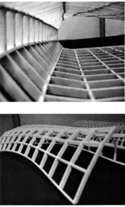
Figure 2.7: Physical model of the NURBS surface
Figure 2.8: Cut sheet layout of ribs
Figure 2.9: Model showing rib components and assembled surface
were identified and pre-defined when initially creating the script.
It is noted that not only is it very time consuming to perform the above tasks manually, but it is also difficult to understand and access the geometry in a wire frame model. The use of scripted procedures both speeds up the process by automatically creating the rib
components and avoids human errors.
Once the script has been written it can be modified, improved or simply re-used for other projects as well.
Preparation of assembling instructions and assembly process
End-user programming is used not only to automate the process of "rib" creation, but also to lay them out in a format that can be interpreted by the Laser Cutter. The script labels the pieces both in the design model and in the cut sheet layouts (Figure 2.8), thus automating the laborious task of preparing assembling instructions. These "ribs" are then rearranged on a sheet, which has the same dimensions as the bed of the Laser cutter. The output size of the fabrication machine is again a limiting factor for the scale of the physical representation, which cannot be increased beyond the size of the biggest component fitting onto the Laser cutter bed.
Once the layout was complete and the ribs were cut, they were assembled to fabricate the approximated NURBS surface. The tolerance value for the ribs was changed after a few initial tests. Defining the tolerance within the program was found most useful at this stage because as the parameter for the tolerance value was changed in the script, the connection details in the ribs would be updated automatically to accommodate the new tolerance values. Another important observation during the assembly process was the orientation of the ribs with respect to the labeling. Labeling helped identify and orient a piece, but it was still necessary to constantly
refer to the digital model while re-assembling the physical sketch surface model (Figures 2.8, 2.9).
Results
Variations: As mentioned earlier the ribs were programmed to follow the UV lines of the NURBS surface model. The density of the UV lines were changed by "re-building" the surface in the software. Thus by changing the density of the UV lines in the digital surface model, the density of the ribs was controlled programmatically
(Figure 2.10).
Figure 2.11 shows a variation of the script, where the surface was "re-built" such that the distance between 2 consecutive contours in a chosen direction (lets say, U direction) was the same as the thickness of the material being used (in this case the chip board). Thus, there was no need for members in the other direction (in this case, the V direction). The script would now slice up the digital model into thin, horizontal layers. Eventually the entire model was fabricated by gluing together these ribs layer by layer. By adopting this methodology the digital solid model was turned into ribs that could be assembled together in a way that was very similar to the deposition printer, but in this case the layers were made out of the chip board and not the starch powder used by the deposition printer. This method is analogous to the software of the deposition printer that produces a very long sequence of instructions for the depositing pellets of the material, and then the fabrication machine executes these instructions one by one.
Post-Script
- Here the NURBS surfaces are approximated by following
the isoparametric curves that define the NURBS surface, leading to "true" tectonic expression of the 3D surface. However, it would be very difficult to produce larger scale, actual building components, as they pose a challenge of fabricating doubly curved structural
Figure 2.10: Variations
Figure 2.11: NURBS surface generated by contouring
members and require precise positioning in the construction assembly. In the case of the above exploration, it was possible to bend and twist the chip board to follow the U and V isoparametric curves and to produce quick physical sketch models; but it would not be possible to do this with buildings at real scale, for example with materials like steel.
- For the same reason as mentioned above, it is possible to make sketch models for partially curved NURBS surfaces, where the isoparametric lines bend within the limits of the bending stiffness offered by the chip board or alternative material that is used, and hence cannot be applied for highly sculpted surfaces or complex topologies.
- A good understanding of surface properties, underlying algorithms mathematics of surfaces and knowledge of how the software creates the surfaces is very important. Such information is necessary to have access and control over the CAD model.
2.1.2 Approximating surfaces by
Meshing/Triangulation
This section describes an alternative way of rapid prototyping and manufacturing physical representations of surfaces using meshing/ triangulation as a production strategy to approximate them. By prototyping surfaces this way, physical models at various scales, including full scale building components, can be produced.
Digital Representation of Surfaces
-Tessellation,
Triangulation and Surface Patches."
Surface modeling systems represent curved surfaces internally by storing parameter values that are required to define them. These parameters are used in conjunction with appropriate mathematical formulae to generate accurate digital representations of surfaces as required.
An alternative approach is to approximate curved surfaces by small planer facets - just as a curved line can be approximated by small, straight segments. These facets are often triangular, since triangles are always planer, but facets of other shapes can be used as well. This technique proves to be adequate for many practical purposes and it simplifies computational tasks that a surface modeling system must perform. It is widely used in contexts where precise representation of surfaces is not critical.
Where a surface is approximated by a mesh of triangles, linear interpolation between the vertices of any triangle produces points that rest on the plane defined by its three points. If the surface is approximated by a mesh of quadrilaterals, however, the vertices of a given quadrilateral do not necessarily lie on the same plane. In this case, linear interpolation between them will produce a bilinear
Figure 2.12: Great Court, British Museum, London
curved surface. Quadrilateral bilinear patches provide an alternative to triangular plane facets for representation of curved surfaces.
This experiment looks at how the technique of approximating surfaces by bilinear surface patches/ triangulation, primarily used by surface modeling systems for efficient visualization of surfaces, can be harnessed to produce physical sketch models of surfaces.
Precedent Examples
Tessellation of surfaces has been attempted by many architecture firms in recent years. Triangulation is the most commonly applied form of planner tessellation. The British Museum' (London) designed by Foster and Partners (engineers Buro Happold in collaboration with Chris Williams), is one of the most prominent examples of surface approximation by tessellation. It has a triangular framework consisting of 4,878 hollow rods and 1,566 connecter nodes, different from one other and fabricated with computer controlled fabrication. The final surface was then filled with 3312 glass panels. Another example of triangular tessellation is the glass roof of the DG Bank (Berlin, Germany) designed by Frank O Gehry and Associates (engineers for the glass roof Schlaich Bergeman and Partners). Here a triangulated space frame is constructed of solid stainless steel with star shaped node junctions, each milled using a 5 axis milling machine. The frame is infilled with about 1500 different glass panels. Other examples include the courtyard roofing for the Museum fir Hamburgische Geschichte by von Gerkan, Marg und Partners"" (engineers for the glass roof Schlaich Bergeman and Partners).
Experiment 2:
Approximating Surfaces by meshing / triangulation
Geometry - Coons patch
Material - Chip Board, High Density Foam
Fabrication Machine - Laser Cutter, Milling Machine
Generative Method - Auto LisplAutoCAD
Production Strategy - Surface approximation
by triangulation and assembly
Task
The ambition of this exploration was to directly realize the meshing pattern used to represent surfaces in the computer model with the physical, so that representations at various scales, including full size building components, can be manufactured.
Methodology
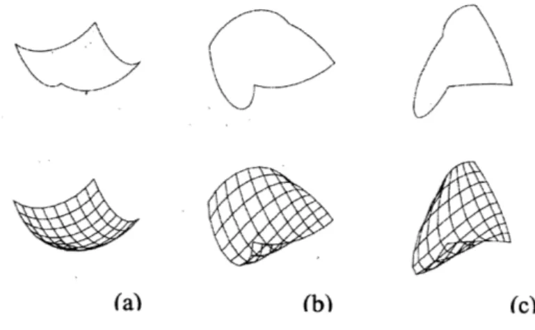
The idea of curved surface patches may be extended in various ways to provide curved surface representations. An obvious generalization of the bilinear patch, for example, is a patch bounded by four arbitrary curves. This type of patch, provides more precise control over slopes and is know as a coons patch*"". This experiment harnesses the surface approximation technique of a coons patch for creating physical representations from wire frame models.
Figure 2.13: Coons
Patches;
-~ (a) Edges of equal 2
nd-order curves, vertices regular
(b) Edges of arbitrary 2"d-order curves, vertices regular
(c) Edges of arbitrary 2"d
order curves, vertices arbitrary
\~ \\
'~ ---
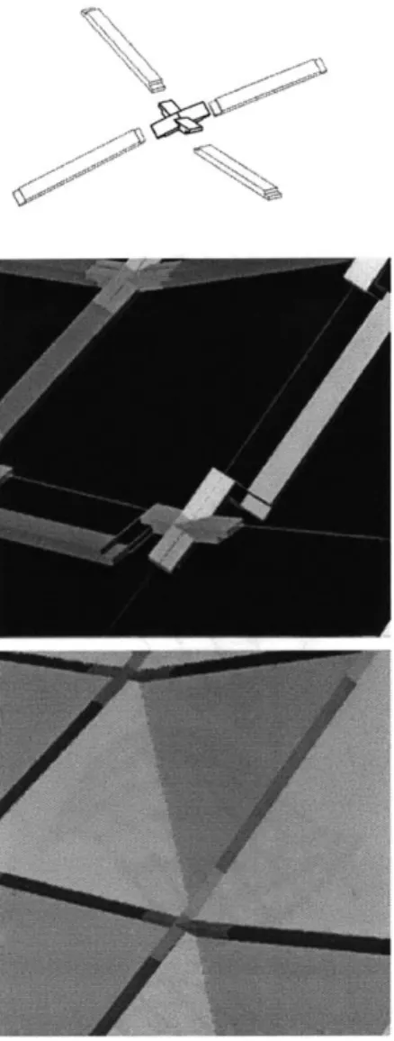
~-~-Figure 2.14: Proposed
node-bar system for the
approximated Coons patch surface
Figure 2.15: Screenshots showing generating of members using scripting procedures
Figure 2.13 shows how the underlying algorithm of the surface modeling system, based on four bounded arcs defined by the user, generates a meshed surface. Each mesh module is a bilinear curved surface.
The node conditions of the meshed surface are analyzed first in this study. All node conditions are unique and have 4 component mesh members on different planes that intersect at the node. Interpolating the nodes with lines results in double curve members that cannot be fabricated using 2D fabrication machines. Therefore, each mesh member and associated nodes must be manufactured individually. Figure 2.14 shows a bar-joint junction detail (very similar to a tongue and groove joint) that is finalized for this exploration.
Each member and node junction in the surface patch is accessed line by line, point by point to create a 3D solid model and 2D profiles that are interpreted and manufactured by the fabrication machines. This is a very time consuming and laborious task.
It is also observed that each bar-joint junction detail requires the same underlying procedure for creating the geometry of the bars and joints, this could be defined by a point location of a node junction and four direction vectors in 3D Cartesian space, representing the directions of the mesh members intersecting at that node junction, thus giving the opportunity to script or program the 'bar-joint junction detail'.
This procedure is systematically defined and programmed into a script that creates a coons surface, using an existing procedure from
the CAD software, and extracts the information that is required, creating the 'bar-joint junction detail'. User input of various variables, like tolerances, thickness of material and number of mesh modules in X or Y or both directions, is required to instantiate the script. Running the script creates digital models for all joints and bars needed to fabricate the surface.
The frame of the meshed surface can be fabricated by assembling bars and the joints. However, the doubly curved surfaces, bounded by the four bars that constitute a module of the mesh, have to be covered with panels. Doubly curved panels cannot be fabricated by 2D fabrication devices. Therefore, these four sided modules are divided by lines that runs across the diagonal of the mesh module, sub-dividing the quadrilateral mesh module into two triangles. Now these triangular panels can be fabricated using the laser cutter (Figure 2.16).
The code is then re-programmed to triangulate all the panels, label them and lay them out flat on a sheet so that they could be interpreted and manufactured using the laser cutter (Figure 2.17).
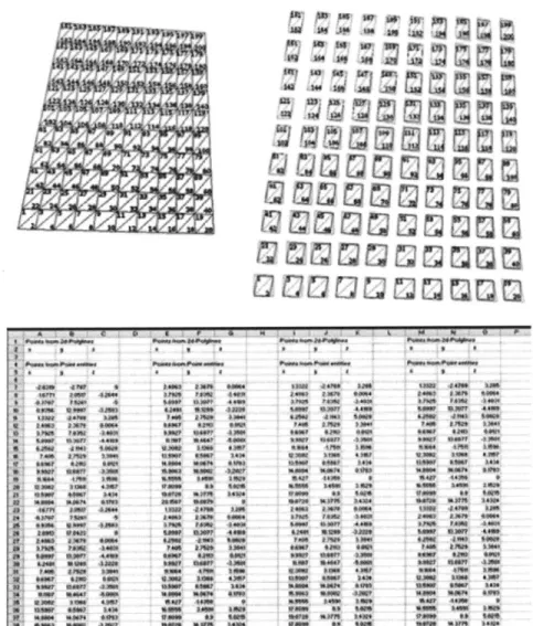
Another challenging task is to physically assemble these components exactly like the digital model. Precise 3D locations for all nodes are required to do this. An interface to an excel spreadsheet is programmed for this. Running the script automatically creates a new excel spreadsheet, containing x, y, z coordinates for each node, with respect to the origin located at the bottom left corner of the surface (Figure 2.18).
Figure 2.16: Screenshots showing the generation of system components through scripting
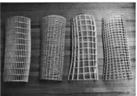
Results
The following images show physical models of surface patches. Variations of this surface can be fabricated by altering the parameters of tessellation, where the surface tabulations in X or Y or both directions are changed (similar to the previous experiment).
Note: The node detail could be fine tuned and optimized as the design develops. Since the joint is generated parametrically, its definition could be re-programmed in script and appropriate changes would be updated at all node junctions.
Post Script
- This is an effective way to make sketch models, however the user does not have control over the surface except for changing the spacing or density of the meshing. Here the meshing is created by the underlying algorithm of the surface modeling software. Similarly, other multi-sided tessellation patterns are also possible and are provided by many software packages, where the user can choose the tessellation pattern of their choice. However, as stated above, the user does not have much control over the algorithms besides changing the tessellation parameters and exploring various scenarios.
- Custom subdivision patterns, like those proposed by Frank
Gehry's office (Dennis Sheldon), could be programmed whereby desired patterning is programmed instead of harnessing the underlying algorithm of the surface modeling software.
- Another strategy is to design the algorithm to generate the surface.
For example, the British Museum roof, where the surface is analytically and mathematically defined, has a quadrilateral mesh of
Figure 2.19: Screenshots
showing the mapping of a script to a wire frame
~Fwun~NuflEr~1~Tmr
-the surface that is triangulated by selectively interpolating intersecting nodes in an aesthetically interesting way"'.
- Other ways of triangulating, like projecting a
two-dimensional triangular pattern on a surface using surface modeling systems, could also be adopted.
Regardless of the way triangulations or any other patterning is achieved, the above strategy is useful for making physical sketch models using Digital modeling with generative methods and fabrication machines. in~ %b vk 4, XI ut
usQQQQQQQQ-Iwo 4 1. *t **" 4 04 %0"5 MOW#. * MW - * 14 4W wra* * *We5 ISOMa rM s $I mow W4 "W 030,"4 #ft* 1*0* 45 55 tow "30 a"4~U 5040S Sm *VMA S 5 5 4 5 5 SW0" 445M 1, m *Is 45W tow* 4W 55 0*Wi 454N 555 WOWS ot W* 4 955 WM 454 45* SW 45* 443* SW 55*45 4',- 4-44*, 4455 445* 5*55 S SW sq. SW NW SW 445* 4-*555 5-*5* 4W .555* 4* 1456 4W 45* 54-SWFigure 2.20: Images showing physical models and assembly process
Figure 2.17: Screenshot of cut sheet layout generated by scripting * S 5 1Sw 4 fto t5 W" 1"40 SW 14,10 4W SAW OW7 SW #i"5 14W ~W .40" 4*56k **ft &PW 15* 4 Figure 2.18: Excel
spreadsheet of clouds of point generated by scripting tw * n 44 4*0
14W
9
01m #at W4 0* A 514 .W ta j.4W 4*4W A VA* 55W * 147 5W 4A" PWnw 4W 44 **44" 4 32 11 ?1 r V I I IFigure 2.21: Construction of a translation surface
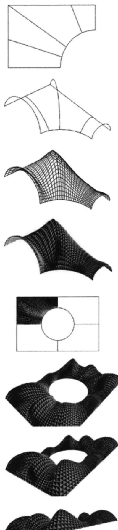
2.1.3 Approximation of translational surfaces
This exploration looks at how Digital modeling with 2D fabrication machines and end user programming are used to make sketch physical models with faceted approximation of translational surfaces. Programming is used to define the geometry and the CNC tool paths, so that approximated surfaces can be physically modeled at various scales.
What are Translational Surfaces"
Several projects discussed in the previous section show that free double curved surfaces can indeed be constructed with triangles, but unfortunately cannot achieve the cost effectiveness of construction made with rectangular glazing. Translational surfaces correspond to a vast variety of shapes that are made with identical, plane rectangular glazing. Such surfaces are designed with a geometrically smart technique that could allow construction of shapes by using plane quadrangular tiles.
If, for example, a curved line (approximated by small, straight segments) floats across another curved line (also approximated by small, straight segments) positioned perpendicularly to it, the resulting geometry can be covered with identical planar quadrilateral tiles to form an elliptical curvature layout (Figure 2.21). The first curved line is the generatrix and the second curved line is the directrix. Thus, a variety of surfaces can be formed with straight edges and can be constructed, which means that they could be individually supported. However, the directrix and generatrix do not have to necessarily consist of geometrically simple curves, but can be defined as random spatial curves, and thus present a vast variety of shapes.
Precedent Examples
Many architectural firms have engaged in designing complex and provocative forms using faceted approximation of translational surfaces. For example, in some of their recent projects Foster and Partners have created complex geometries based on parameterized concatenated torus patches that blend into one another"". Frank O'Gehry and Associates have also developed similar approaches by overlaying pre-constrained parametrically defined surfaces on existing double curved surfaces that result in flat quadrilateral panel
solutions to approximate curved surfaces.
Note: The information of the various intersection nodes for such
kinds of surfaces is often stored as a cloud of points in excel spreadsheets, for precise control of the geometry and for effectively communicating the geometry to various collaborators, engineers, fabricators, contractors etc. This idea of "making" physical models based on information of clouds of point in an excel spreadsheet, is also integrated, by programming an interface between Microsoft excel and the CAD software (in this case AutoCAD). Therefore, a kit of parts can be produced, based on the information provided in the excel spreadsheet, that could be assembled to fabricate the surface.
Experiment 3
Rapid Manufacturing of Faceted Translational Surfaces
Geometry - Translational Surfaces
Material - Chip Board
Fabrication Machine - Laser Cutter
Generative Method - Auto Lisp/Auto CAD
Production Strategy - Surface approximation by Faceting and
manufacturing by self assembly
Task
This exploration began with the idea to create physical scale representations of translational surfaces, analogous to the actual way building components are manufactured and assembled at full scale.
Figure 2.22: Various projects
constructed from translational surfaces, Architects Foster and Partners, London
Methodology
V z /
Figure 2.23: Proposed construction system with frames and plug-in panels
Figure 2.26: Physical model for construction system build using laser cutter
The geometry for faceted approximation of translational surfaces provides a clue for the digital making of these surfaces. The directrix and the generatrix are essential components required to define a translational surface and consist of curves approximated by straight lines that give a natural flat panel solution without any twists. Since these are always on the same plane, they can be substituted with the main frame members that can be laser cut. Also, since the directrix and generatrix are always perpendicular to one another, a straightforward self-assembly system can be adopted for the intersection conditions (Figure 2.23).
The challenge was to find how to make these wire-frame representations of translational surfaces into tangible physical models with a quick, inexpensive design process using generative programming and fabrication machines.
To generate the surface, an End-user program is written which requires an input of 2 arcs (representing the directrix and generatrix) and the number of facets that are desired along each arc. The translational surface geometry is defined from first principles by sweeping the generatrix along the directrix. The End-User Program generates flat quadrilateral tiles and nodal information for translational surfaces.
Once the geometry is created, a construction system is proposed with a main structural frame, an intermediate connecting frame and detachable panels. Figure 2.23 shows initial tests where the proposed system has 3 essential components: a .main frame that support the structure of the surface, pre-fabricated plug-in panels and a sub-frame that connects the main sub-frame to the plug in panels. These components are decomposed into a kit of parts that can be interpreted by the Laser cutter. This system is very similar to the cone exploration which has been discussed in section 2.2, however unlike
the cone experiment where the panels are curved (and are slices of the original surface), the panels here are flat and approximate the translational surface.
Having established a system of components, the next step was to identify the procedure for creating system components and batch-process it to generate all the components from the wire frame model of the translational surface. After carefully identifying and systematically laying out the various steps required for this procedure, the script is re-programmed to automate the generation of all the required system components (Figures 2.24, 2.25).
Preparing assembling instructions and assembly process
The script is re-programmed once again to label and layout the components in a format that is interpreted by the Laser Cutter.
Another important feature of this code is its interface with Microsoft Excel. Not only are the x, y, z coordinates of all intersection nodes saved as an excel sheet as explained in the previous section (often referred to as a point of clouds), but the code could directly understand and interpret the data from a Microsoft Excel spreadsheet. This two way interaction between the CAD software and Microsoft Excel makes it possible to import data from other software into the CAD software and get an output in the form of
profiles a laser cutter can cut.
Figure 2.25: Screenshot of translational surface script
Figure 2.24: Screenshots showing various stages of generation of translational surfaces Figure 2.27: Plaster models of translational surfaces generated by scripting
Results
Figure 2.27, shows images of the sketch models of faceted approximations for translational surfaces. It is noted that a similar system could be adopted for producing building components at full scale, with the main frame as the structural backbone and factory made plug-in panels that can be assembled on site.
Post script
- This exploration demonstrates how direct computer programming of architectural geometry and CNC tool paths can enable "making" of a digital form and related treatment of material. In this exploration programming is also used to create the geometry. By creating the geometry programmatically, using the powerful engine of the underlying CAD software, the user has more control and access to the geometry.
- This exploration also demonstrates a digital based convergence of representation and production, where Fabrication machines are used to represent actual manufacturing methods and techniques.
2.2
Experiment
-
Integrated
Design
and
Manufacturing Process
2.2.1 Task
To test an alternative method for fabricating architecture using a combination of digital modeling and computer controlled fabrication machines, which involves an integrated design and manufacturing process, through the study of a single design case.
2.2.2 Methodology
The methodology is divided into 3 phases. A design phase is first, where an abstract space is designed using an existing digital
Figure 2.28: Digital and modeling platform. The design derivation phase is next, where the physical models of abstract abstract space is resolved, such that it can constructed out of cone composition
components. Finally, the third phase elaborates the design development procedure, such that the components are manufactured using CAD/CAM fabrication machines.
Each phase is associated with its own way of representing the design. These are: the design layout, the construction layout and the cut sheet layout. A design layout is a digital representation of the design with surface information; a construction layout is a digital representation of the design with manufacturable components; and a cut sheet layout is a digital representation of the design with the manufacturable components laid flat on a sheet, which is understood by the laser cutter (CAD/CAM fabrication machine being used).
1.
Design
A set of CAD objects (tapered cones) and CAD operators (Boolean operations) were exploited to create an abstract composition (a set of intersecting tapered cones in this case). Cones were used in this
rT
I
aI
Figure 2.29: Initial tests with system components for a small patch of a developable surface
design exploration because their geometry consists of developable surfaces. These surfaces have curvature in one direction only, which allows the use of paper in their physical representation.
2. Derivation Process
The derivation process is defined as a process by which the design layout for a given geometrical composition is resolved into a construction layout. This process has many key issues relating to the integration of digital modeling with the output required by computer controlled fabrication machines, which revolve around being able to decompose a design scheme into component parts that could be manufactured and assembled. Described below are the various steps taken in the derivation process of the cone exploration.
Establishing a system of components
The first task in the derivation process is to define the various components required to manufacture a developable surface. A construction system is designed such that there are two essential components; the basic supporting framework and detachable panels that can be plugged onto the supporting framework. An intermediate sub-frame is introduced as a connecting element between the main supporting framework and the prefabricated panels, such that the panels could be plugged on to the supporting framework via the sub-frame. This construction system is similar to the panel system that was adopted for the Stata center at the Massachusetts Institute of Technology, designed by Frank Gehry and Associates.
Resolution of the construction system for the geometrical composition.
The next task is to map the construction system onto the design layout of the cone composition. The cone composition has many complex intersecting conditions. It is difficult to fabricate and manufacture a supporting structure along these intersections using the proposed construction system, which relies on the use of 2D
cutting devices for manufacturing components. The form is decomposed such that all intersecting conditions are a part of the panels and the supporting framework is intentionally located in such a fashion that the intersecting cone conditions are avoided. The following steps describe how developable surfaces of the cone composition are sliced into smaller surfaces: 1) Owing to the radial nature of the composition, a cookie cutter method for slicing the design scheme into 8 vertical sections through the center of the base cone is adopted; 2) The next step is to create horizontal sections which are proportional to the vertical sections; 3) A cookie cutting methodology for horizontal sections does not give acceptable results as they are very close to the intersection cone conditions and cut the cone base (in this case the ceiling) in an aesthetically unacceptable way; 4) Various options are tested to establish a set of rules for the location of the supporting framework in the cone composition, for example, a supporting frame at a particular offset distance from the base of every cone; supporting frame lines were intentionally generated to pass through intersection points of other supporting frames and the vertical frame to form a continues ring. (Refer to figure 2.30)
The process of sub-dividing the original surface into small surfaces requires constant input from the designers and cannot be automated.
Figure 2.30: Strategies
adopted for slicing the overall composition into smaller surface patches
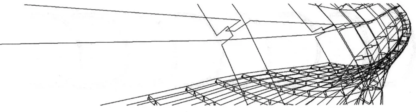
Figure 2.31: Digital derivation of system components based on the wire frame model
*4
t
Figure 2.32: Optimization of joints
After the basic division of the various smaller surfaces is finalized in the cone composition, a supporting structural framework is designed. This is done by offsetting the surface profiles. Today CAD software makes it possible to offset surfaces and extract surface information accurately, making it easier to manufacture and fabricate curved surfaces. A combination of CAD objects and operators (Boolean operations) are used to generate all the system components for the cone composition.
The use of physical models early in the design process was found to be particularly useful. Each generation of CAD model led to the next physical model, which led to further changes in the CAD model, until an acceptable dividing strategy was achieved. Here 3D CAD modeling and corresponding physical models helped the development of the design. This method was particularly useful for optimizing and fine tuning the design, such as in resolving joint details, Figure 2.32 describes a condition where supporting frames at different 3d planes meet. Initially a 3D milled joint (analogous to
5-axis milling at real scale) was proposed. Later the supporting framework was modified by sliding/displacing components, such that there was minimal effect on the overall appearance, and the expensive milling process was avoided. It can be argued that such a change would at some point be proposed by the engineers and the fabricators, but if this level of detail and understanding of the manufacturing process was handled by the designers at an earlier stage, it could reduce a lot of the back and forth movement and streamlining of the over all design and manufacturing process.
Having established a supporting framework, the next task is to make the panels that plug-into the supporting framework via the sub-frame. The sub-frames are derived from the supporting frame by a series of Boolean operations. There are about 72 different panels and each panel has to be sliced from the surface model. Each panel frame