HAL Id: hal-00961328
https://hal.archives-ouvertes.fr/hal-00961328
Submitted on 19 Mar 2014
HAL is a multi-disciplinary open access
archive for the deposit and dissemination of
sci-entific research documents, whether they are
pub-lished or not. The documents may come from
teaching and research institutions in France or
abroad, or from public or private research centers.
L’archive ouverte pluridisciplinaire HAL, est
destinée au dépôt et à la diffusion de documents
scientifiques de niveau recherche, publiés ou non,
émanant des établissements d’enseignement et de
recherche français ou étrangers, des laboratoires
publics ou privés.
Manipulation and optical detection of colloidal
functional plasmonic nanostructures in microfluidic
systems
Martinus H. V. Werts, Florent Allix, Olivier Français, Céline Frochot, Laurent
Griscom, Bruno Le Pioufle, Matthieu Loumaigne, Johanna Midelet
To cite this version:
Martinus H. V. Werts, Florent Allix, Olivier Français, Céline Frochot, Laurent Griscom, et al..
Manip-ulation and optical detection of colloidal functional plasmonic nanostructures in microfluidic systems.
IEEE Journal of Selected Topics in Quantum Electronics, Institute of Electrical and Electronics
En-gineers, 2014, 20, pp.6900613. �10.1109/JSTQE.2013.2284549�. �hal-00961328�
Abstract—The very strong optical resonances of plasmonic
nanostructures can be harnessed for sensitive detection of chemical and biomolecular analytes in small volumes. Here we describe an approach towards optical biosensing in microfluidic systems using plasmonic structures (functionalized gold nanoparticles) in colloidal suspension. The plasmonic nanoparticles provide the optical signal, in the form of resonant light scattering or absorption, and the microfluidic environment provides means for selectively manipulating the nanoparticles through fluid dynamics and electric fields. In the first part we discuss recent literature on functionalized colloidal particles and the methods for handling them in microfluidic systems. Then we experimentally address aspects of nanoparticle functionalization, detection through plasmonic resonant light scattering under dark-field illumination and the electrokinetic behavior of the particles under the action of an alternating electric field.
Index Terms— Biophotonics, chemistry, chemical and biological
sensors, dielectrophoresis, electrokinetics, fluidic microsystems, microfluidics, nanoparticles, nanophotonics, optical microscopy, self-assembly, spectroscopy
I. INTRODUCTION
ODERN developments in light generation (LEDs, diode lasers, robust pulsed lasers), light manipulation (fiber technology) and light detection (CCD, scientific CMOS, avalanche photodiodes) and progress in the development of bioresponsive photonic materials (fluorescent probes, functionalized nanoparticles) have created a host of opportunities for the sensitive detection of analytes in small volumes. This is of great interest for medical diagnostics[1].
M
Here, we describe the combination of the electromagnetic response of nanostructured conductors with microfluidics for miniaturized optical detection. Nanostructures of materials
having free conduction electrons (in particular gold, silver) display resonances at optical frequencies commonly referred to as plasmonic resonances[2]. One particularly versatile type of plasmonic material are colloidal gold nanoparticles, that can be dressed with a nanoscale coating of organic material[3], which can make their plasmonic resonance sensitive to the surrounding biomolecular environment[4], [5], [6], [7].
Such analyte-sensitive gold nanoparticles (Fig. 1) can be used as optical transducers of biomolecular signals. We focus on approaches where the transducing particles are in suspension, instead of immobilized on a substrate. These approaches have the advantage that the interaction of the sensing nanomaterial with the analyte can take place in the entire fluidic volume, instead of only at the sensor substrate. In the latter case, the sensor sensitivity may be limited by the mass transport of the analyte towards the active surface[8], [9]. An additional advantage is that in free suspension, biomolecular recognition may be less hindered than at a biofunctionalised substrate. When using optical read-out of the bulk suspension, the optical signal is integrated over the entire optical path that is sampled. This optical read-out can be readily achieved in microfluidic systems that are made out of transparent materials.
Martinus H. V. Werts, Florent Allix, Olivier Français, Céline Frochot, Laurent Griscom, Bruno Le Pioufle,
Matthieu Loumaigne, Johanna Midelet
(Invited Paper)
AUTHOR MANUSCRIPT, DOI: 10.1109/JSTQE.2013.2284549
Manipulation and Optical Detection of Colloidal
Functional Plasmonic Nanostructures
in Microfluidic Systems
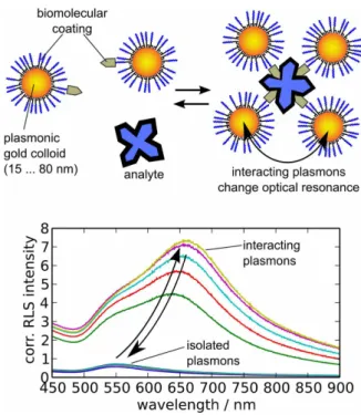
Fig. 1. Concept of plasmonic biosensing in using functionalized colloidal particles in suspension. Bottom: typical evolution of resonant light scattering response of acid sensitive gold colloids[6].
This work was supported by the Agence Nationale de la Recherche (ANR JCJC grant COMONSENS).
M. H. V. Werts, L. Griscom, M. Loumaigne, and J. Midelet are with the
Laboratoire SATIE (UMR 8029) and Centre National de la Recherche Scientifique (CNRS) at the Ecole Normale Supérieure de Rennes,
F-35170 Bruz, France (e-mail: [email protected]; [email protected]; [email protected]; [email protected]).
F. Allix and C. Frochot are with the LRGP (UMR 7274) and Centre
National de la Recherche Scientifique (CNRS) at the Ecole Nationale Supérieure des Industries Chimiques, F-54001 Nancy Cedex, France
(e-mail: [email protected]; [email protected]). O. Francais and B. Le Pioufle are with the Laboratoire SATIE (UMR 8029), Ecole Normale Supérieure de Cachan, F-94235 Cachan Cedex, France (e-mail: [email protected]; [email protected]).
The handling of nanoparticles and their assemblies in microfluidic systems can be achieved both by fluid mechanical phenomena[10] related to the fluid flow in microstructured channels, but may also be achieved by external fields. The mechanical methods are sometimes called 'passive' methods as no additional fields other than the velocity field of the fluid are necessary. For 'active' manipulation of objects, external fields are applied, for example electric fields by incorporating microelectrodes into the systems. Manipulation of mixtures of nanoparticles using fluid dynamics and electric fields can give extra selectivity and sensitivity to a detection system by selecting and concentrating specific particles in the detection zone.
This paper first gives an overview of the recent literature in functionalized gold nanoparticles for optical sensing, the handling of such nano-objects using microfluidic systems using fluid mechanics and electric fields. Then we describe new results towards the combination of plasmonic nanoparticles, electric fields and light for sensitive biodetection in microfluidic systems.
II. ANALYTE-SENSITIVEANDBIOFUNCTIONALIZED PLASMONICNANOPARTICLES
Depending on the size, shape and degree of aggregation and nature of the protecting organic shells on their surface, suspensions of gold nanoparticles (AuNPs) can display a wide range of colors, from red to blue. The strong coloration is a result of a resonant interaction of light with the conduction electrons in these materials. This interaction leads to a number of fundamental phenomena (thermal, optical and electrical) in and around the AuNPs that have fueled as already mentioned new imaging and therapeutic biological applications.
AuNPs possess excellent compatibility with many types of chemically and biologically active molecules. Because of their high surface area to volume ratios, AuNPs serve as an excellent scaffold to immobilize large quantities of organic or biomolecules. AuNPs (e.g., citrate capped) are mostly negatively charged, and can therefore be tailored to electrostatically interact with certain positively charged biomolecules that in turn can have a highly selective interaction exclusively with the target analyte of interest. Moreover, It is possible to functionalise AuNPs[11] for example with metal chelating groups[12], or biomolecular functional groups [13], [14] .
Because of this chemical carrier capability, gold nanoparticles have been extensively used as transporter of various therapeutics probes for sensing and imaging a wide range of analysts/targets such as proteins, cells and nucleic acids, including multimodal imaging and tumor targeting. There are many excellent specialised reviews in the area of AuNP design and use, including both broad reviews[15] and more specific reviews of GNPs covering the chemistry and synthesis[16], [17], physical, chemical[18] and optical properties[19],[20] biodistribution and safety[21], heat generation[22], and biological applications[23], [24], [25] including cancer therapy[26], [27], [28], [29], [30].
For detection of analytes, colloidal metal particles can be designed to display an optical response that is sentive to certain analytes[31], [32]. Sensing schemes based on the (bio)analyte-induced assembly of metal nanoparticles are currently receiving considerable attention, with assembly based on DNA strands[5], [33], [34], [35], [36], [37], biotin-avidin[38], antibody-antigen[39], cation chelation[40], hydrogen bonding[41], [42] etc. We recently demonstrated the reversible modulation of the RLS response of thioctic-acid capped gold nanoparticles[6] as a model system for analyte-induced assembly of plasmonic nanoparticles.
The interparticle plasmon coupling depends strongly on the interparticle distance [107], with very small distances (< 1 nm) producing large shifts and increases in intensity of the plasmon resonance. The plasmon coupling diminishes drastically for larger distances. Functionalization of the nanoparticles with large biomolecules (proteins) creates a spacing between particles which reduces detection sensitivity. This reduction can be counteracted by using nanoparticles of larger diameter. More precisely, the interparticle plasmon coupling depends on the ratio of the particle distance and the particle diameter[19], [108]. It can be anticipated that non-spherical particles can further enhance sensitivity[16].
Another important point is the colloidal stability of the functionalized particles in the complex environment of real biological samples. Particles can be coated in such ways that they do not interact non-specifically with molecules present in the sample, and that they remain intact in a complex sample (see
e.g. [36], [41], [42], [43]). The success of obtaining a specific
plasmonic response depends on the actual application. Additionally, a microfluidic architecture may provide for sample pre-treatment that removes interfering components before adding the sensing plasmonic particles.
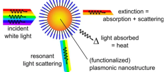
III. OPTICALDETECTIONANDIMAGINGOF NANOPARTICLESINMICROFLUIDICVOLUMES The interaction of plasmonic nanoparticles with light leads on one hand to absorption of the luminous energy, on the other hand to resonant light scattering where the energy is re-radiated (Fig. 2). The relative contributions of absorption and scattering are determined by the size and shape of the plasmonic objects. Recently, we developed a simple method to measure the efficiency of resonant light scattering by nanoparticles and their assemblies in liquid suspension[6]. Interestingly the optical cross sections for light absorption and light scattering by gold and silver nanoparticles are very large. They may be as large as several times the geometrical cross section. In comparison, organic dyes typically have optical cross sections that are less than 5% of their physical area. When light is absorbed by AuNPs, the energy is almost completely dissipated in the form of heat[43]. Light resonantly scattered by AuNPs enables very sensitive detection of the particles, down to the single particle level[44], [45], [46], [47], [48].
Fig. 2. Photophysical processes of plasmonic nanostructures: resonant light absorption vs resonant light scattering
In addition to the intrinsic optical response, there can be a strong electromagnetic and sometimes direct electrochemical interaction between the AuNP and a molecule linked to its surface. This interaction leads to the modification of the optical response of both the AuNP and the molecule. A well known effect in this respect is the very strong quenching of a fluorescent molecule (a fluorophore) near the surface of AuNPs[49], [50], [51], [52]. In general, this quenching prevents the sensitive fluorescent detection of AuNPs carrying flurophore. Nonetheless, the quenching effect can also be
exploited to detect environmental pollutants such as mercury inside microfluidic device[53]. Quenched fluorophore functionalized gold nanoparticles are injected in a microfluidic-device in presence of the pollutant to detect. Since the pollutant has a bigger affinity for the AuNP surface than the fluorophore, the latter is ejected from the particle surface into the solution. Consequently the fluorophore is not quenched anymore and the amount of fluorescence measured inside the microchanel reflects the concentration of the pollutant to detect. An other way to indirectly detect the presence of AuNPs (and AgNPs) is to exploit the localized enhancement of the electromagnetic field at the surface of the AuNPs. This enhancement leads to the well-known surface-enhanced Raman scattering (SERS). The feasibility of using this technique inside a microchannel has been shown[54], [55].
The simplest way to detect and image AuNPs inside microchannels is to use their large intrinsic extinction and scattering cross sections. The extinction of light by plasmonic nanoparticles can be observed in brightfield transmitted light microscopy. This requires a relatively high concentration of gold nanoparticles since the optical path length of the microchannel is small compared to a traditional spectroscopic cell[56]. Transmission spectra of AuNPs at very low concentration can be recorded if the measurement is done collinearly to the microfluidic channel. Ibarlucea et al.[57] present a convenient optical setup. The incoming light is injected into a PDMS polymer-based microfluidic system via an optical fiber coupled with a 2D lens fabricated in the polymer. In order to increase the optical length reflection mirrors (made using total reflection at the air-polymer interface) are positioned along the microfluidic channel. The transmitted light is then coupled to a second optical fiber and sent to a spectrometer.
Imaging AuNPs with optical brightfield microscopy is quite challenging, and dark-field detection offers better sensitivity. A dark background can be obtained by studying only the light scattered by the AuNPs[6], [58]. AuNPs of diameters > 40 nm are sufficiently good scatterers to be imaged at the single particle level. Once single nanoparticle are imaged, their movement and interaction can bring additional characterization of the system. For instance, the study of the Brownian motion associated with nanoparticle tracking permits to obtain the mean size and the distribution size of AuNPs[59].
Scattering is an elastic process. The excitation photon and the re-emited photon have the same wavelength and consequently they can not be separated with an optical filter. They have to be physically separated with the corresponding optical set-up. Darkfield microscopy is traditionally performed with a dark-field condenser. The aim of such a device is to create a ring shaped excitation beam. The beam is focused onto the sample so that the excitation light is not collected by the microscope objective whereas the light scattered by the sample is collected.
However, microchannels give directly the opportunity to achieve a dark-field optical setup, having the microchannel act as a waveguide. This illumination technique is very convenient and cost effective. As shown by Zhu et al. [60], it can easily be adapted to transform a cell phone into a fluorescent imaging cytometry platform. The coupling efficiency of the light can also be increased with PDMS 2D lens[61].
IV. MICROFLUIDICNANOPARTICLESORTINGAND PURIFICATIONUSINGFLUIDMECHANICALPHENOMENA Microfluidic devices offer many possibilities for separation and accumulation of particles and small aggregates prior to detection, thus increasing selectivity and sensitivity. Fluid mechanics in microchannels can be utilized for achieving this.
In this respect, many efforts have been devoted to separation, concentration and purification of micrometer scale objects, such as biological cells as well as nano scale particles.
Microfluidics have been well suited to these tasks as their dimensions result in a low Reynolds' number allowing laminar flows. This effect simplifies many of the physical parameters that can play in the concentration or separation of molecules and objects. Typical microfluidic particle separation schemes use an external force applied perpendicular to the flow direction. To successfully separate particles an active separation mechanism can be employed where particles are labeled and a force is imparted on the objet and collected downstream. This is the principle used in miniaturised FACS[62] (fluorescence activated cell sorter) and Coulter counters[63].
In passive particle separation systems, a force, either internally or externally generated, is continually applied to a solution of particles where forces are selective[64]. The microsystem is then tuned such that the forces select for the particle desired. A wide variety of external forces can be used for particle separation such as: electrophoretic, magnetic, acoustic, optical, thermal or gravitational forces, but microfluidic flows impart selective internal forces, that must be taken into consideration in all cases.
The most simple of microfluidic channels will naturally filter particles for size due to diffusion and by internal hydrodynamic forces. In pressure driven flows a cross-section of the laminar flows will have a parabolic profile known as a Poiseuille flow. In general the flow rate at the wall will be close to zero, due to non-slip conditions while the center will be traveling the fastest. This parabolic profile exerts a lift force on larger particles so that they tend to migrate to the center of a channel.
Likewise, one of the most simple filters, known as the H-filter, takes advantage of the fact that smaller particles or molecules diffuse faster than larger ones[65]. When used quantitatively, this phenomenon can be used to measure diffusion coefficients of different types of nanoscale objects[56]. A homogenous mixture of particles are introduced into a flow containing a buffer solution, where the smaller particles will diffuse into the buffer solution and the larger particles will stay in their flow lines to be collected. Multiple passes can lead to purification[7]. In this case, however, the larger particles are selected, while the smaller ones are diluted.
However, when selecting for smaller particles more complex methods have to be employed. One such method is Pinched Flow Fractionation (PFF) where a laminar flow is thinned by introducing it into a fast flowing buffer solution. If the pinched laminar flow width is less than the radius of the larger particle the larger particle will diffuse out of this flow due to the wall effect lift force and thus, the larger particle can be separated from a smaller one. Each particle size can be collected independently downstream.
Similar to PFF the geometry of a microfluidic system can be tuned such that a size-dependent deterministic lateral displacement (DLD, Fig. 3) mechanism can be implemented using a staggered micropost array. The arrangement is made so that each row of a regularly ordered line of microposts are slightly shifted laterally so that on a whole objects larger than a certain size will follow the large flow lines in one direction, and the smaller particles in the other direction. Fractionation is determined by the size of the gap and the post-array offset. The gap size limits the large particle diameter due to clogging, whereas the shift or offset is critical to determining the critical particle diameter that is filtered. Inglis et al.[66] determined that with a small offset particles with a diameter 1/5th of the gap size can be selected for in a single array. To separate multiple sizes or scales greater than 1/5, multiple arrays can be used.
Fig. 3. Deterministic lateral displacement (adapted from Ref. [67], with permission from AAAS)
If current flows are slowed sufficiently, diffusion becomes predominant in DLD systems, and a Brownian ratchet can be created where the faster diffusing smaller particle is deflected laterally due to the asymmetric post array[68], [69].
All the above systems operate on either the wall effect lift forces or diffusion, but other geometrically dependent internal forces may come into play. Inertial forces in combination with hydrodynamic forces can be exploited in a microsystem to create ordered flows where different particle sizes can be selected for[70], [71], [72]. In a curved microsystem with rapidly moving fluids, the faster moving center part of the stream will be subject to inertial forces, inducing eddy currents, called Dean flows, in the channel. The cumulative effects of the induced Dean flows and wall induced lift forces will form ordered particle flows dependent on size. Bhagat et al. were able to demonstrate size-dependent particle separation using inertial effects in a spiral shaped microfluidic system[70]. Fine tuning the flow rate, and curvature, the authors were able to separate 7.32 µm and 1.9 µm particles, by balancing the Dean lift and Dean drag forces the larger particles to migrate to the inner wall, and the smaller particles to the outer wall of the spiral shaped system. Di Carlo et al. further demonstrated (Fig. 4) that inertial forces in asymmetrical serpentine microchannels can not only laterally displace particles, but can also impart a sequential order[72].
Fig. 4. Ordered particle flow due to inertial and hydrodynamic forces in asymetrical serpentine channels (reproduced from Ref. [72], copyright © 2007 by the National Academy of Sciences)
V. HANDLINGANDTRAPPINGOFCOLLOIDAL (NANO)PARTICLESUSINGELECTRICFIELDS In general, handling and trapping of particles having sizes larger than 1 µm in microsystems using an electric field is based on the Coulomb force [73], [74]. In the case of charged particles, electrophoresis causes the particles to follow the electric field
lines in relation with its electric charge. However, for polarizable neutral particles submitted to an electric field, dielectrophoresis (DEP) is widely used[75], [76]. DEP offers trapping, focusing and separation capabilities[77].
In the case of DEP an electric field gradient is needed to induce a dipole within a polarisable particle. The conventional DEP force for a spherical particle suspended in a medium of relative permittivity εm is given as:
(Eq. 1)
with rpart the radius of the particle, E the electric field. Re|KCM|
is the real part of the Clausius-Mossoti (CM) factor which highlights the polarization of the particle in the medium. The CM factor is given by the relation:
(Eq. 2)
where is the complex permittivity ( , with εx and σx being the permittivity and the conductivity of the
medium (m) and the particle (p), respectively), and ω the radial frequency of the electric field. KCM depends on the frequency.
The sign of KCM determines the direction of the force. The DEP
force will push the particle towards high electric field gradients in case of positive value, respectively towards low electric field gradient for negative value. Usually, the CM factor is determined based on simple theoretical models, but approaches to determine this factor experimentally have been proposed[78].
As one can notice, by controlling the properties of the medium and the frequency used for DEP, it is possible to switch between positive and negative DEP. Usually positive DEP is used for trapping[79] whereas negative or positive DEP can be applied to filtering applications[80]. Combination of both filtering and trapping offers the possibility of particle separation[81].
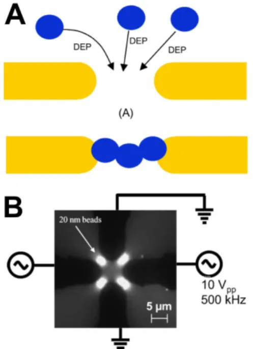
Despite the large (cubic) dependence of the DEP force on particle radius, the greatly reduced DEP force for nanoparticles (10 - 100 nm diameter) can be compensated by using microscale gap electrode in order to locally increase the electric field strength. As presented in a work by Zhen et al.[82], DEP can be used to concentrate 20 nanometer beads between thin electrodes separated by gaps smaller than 3 µm (Fig. 5). The frequency used for DEP in this case was 500 kHz with a voltage amplitude of 10 Vpp.
Fig. 5. A. Principle of nanoparticle trapping by dielectrophoresis using small-gap electrodes. B. Results obtained with 20 nm latex beads attracted to high electric field regions between electrodes. (reprinted from Ref. [82] with permission from Elsevier)
This principle can be applied to metallic or isolated nanoparticles that can be assembled. An example with 10 nm gold nanoparticles is given in Ref. [83]. Depending on the applied voltage, it was shown that the interaction between nanoparticles and the electric field can be described by an electrostatic force (close to the electrodes) or a DEP force (between the electrodes). The gap between the electrodes was reduced from 150 nm down to 30 nm, using e-beam lithography. In an other work nanoparticles were concentrated under microfluidic flow by using DEP with curved microelectrodes included in the flow channel[84]. This offers the possibility for studying the optical properties of nanoparticles in relation with their spatial concentration gradient generated by DEP forces. Experiments were conducted with 80 nm tungsten trioxide (WO3) and 220 nm polystyrene particles, both Raman active.
Electrode pairs with a gap of 20 µm were replicated a large number of times in the channel to achieve a cumulative concentration effect.
Fig. 6. Combining positive and negative DEP for the selective separation of particles, in this case the separation of blood cells from DNA biomarkers and nanoparticles. Positive DEP is used for nanoparticles being trapped on the electrodes, whereas negative DEP is used for catching large particles (blood cells) in between electrodes. (reproduced from Ref. [85], copyright © 2012 Wiley-VCH Verlag GmbH & Co. KGaA, Weinheim, Germany)
When isolation of particles is needed, DEP can be a good solution. For example, this concentration can be used for
trapping drug delivery nanoparticles (40 nm) within microarrays of electrode associated in order to get positive and negative DEP zone[85]. Applied to the extraction of nanoparticles and DNA biomarkers from whole blood, positive DEP is generated for driving small particles onto the electrodes (high field areas, Fig. 6) and negative DEP for driving larger particles such as blood cells towards the region in between electrodes (low field areas).
As we notice, DEP is directly connected to the field gradient but is highly reduced with the reduction of particle radius. The paper by Tornay et al.[86] gives a good example of particle handling versus dimension. The solution for increasing the DEP force is to reduce electrode dimensions and/or to increase the voltage applied on electrodes. In both cases, not only DEP will increase, but also other AC electrokinetic effects as described by Ramos et al.[87].
Thermal effects associated with the electric field can induce electrothermal forces[88], buoyancy effects or AC electro-osmosis[89]. Scaling laws study can be achieved in order to estimate the dominant forces[88]. Competition between DEP effect, electro-osmosis and electrothermal motion has been characterized on 2 µm and 200 nm particles showing the strong dependance with voltage, medium conductivity and particle size[89].
In the remainder of this paper we will describe recent work from our group on the combination of functionalized colloidal gold nanoparticles and optical detection in microfluidic systems under electric fields.
VI. ORGANICLIGANDMOLECULESFOR BIOFUNCTIONALIZATIONOFCOLLOIDALGOLD
PARTICLES
In order to avoid unwanted aggregation and degradation of colloidal gold particles upon exposure to saline aqueous and biological media, the particles need to be coated with specific molecular layers. The materials for coating the particles can be biological macromolecules (proteins[32], [90], [91], [92], DNA[5], [34]), polymers[93], [94], or small ligand molecules that display a particular affinity for metal surfaces[95], [96]. Previously we investigated tetraethyleneglycol-terminated alkyldisulfides[51], to which we attached fluorescent molecules. The fluorescence of these molecules is extinguished when the ligand is attached to the particle and this phenomenon can be used as a nanoprobe for studying ligand-particle interaction. Using fluorescence measurements[50], [97], we were able to demonstrate that this type of disulfide ligands may spontaneously detach from the nanoparticle when in suspension at low concentration. Such spontaneous desorption is undesirable in biological applications.
This prompted us to study different ligand molecules based on thioctic acid (or lipoic acid), as shown in Fig. 7. Thioctic acid had already been shown to stabilize gold nanoparticles[98]. Moreover, derivatives of thioctic acid with longer-chain polyethylene glycols were found to be efficient protecting ligands for various types of metal and semiconductor nanoparticles[99], [100]. In these ligand molecules the sulfur atoms (which convey the chemical affinity for the nanoparticle surface) are part of the same ring system which is expected to confer additional stability to the ligand-nanoparticle bond.
Fig. 7. Chemical structures of the ligand molecules that were synthesized and investigated for the functionalization of gold nanoparticles.
TA-PEG(4)-OMe is aimed at protecting and stabilizing gold nanoparticles. A short, four unit tetra(ethylene)glycol spacer was used, in the hope to optimize the plasmonic response upon particle aggregation, which depends critically on interparticle distance[101]. TA-PEG(4)-NH2 is a useful chemical
intermediate permitting the introduction of functional molecular modules into the functionalized gold nanoparticles. For instance, it is used for preparing the biotinylated derivative TA-PEG(4)-biotin. The purpose of this ligand molecule is to place biotin groups on the surface of the nanoparticles. Biotin is very well known to have a high affinity towards streptavidin (and other variants of the avidin protein), which - according to the literature[102] - can be used to selectively assemble gold nanoparticles in the presence of this protein.
A. Chemical synthesis of ligand molecules
We used an efficient, simple and inexpensive route to synthesize the three ligands of interest based on tetraethylene glycol-appended thioctic acid. TA-PEG(4)-OMe was prepared in four steps from commercial tetraethylene glycol monomethyl ether. This strategy is derived from the one used for TA-PEG(4)-NH2 prepared in five steps from commercial
tetraethylene glycol. Bakleh et al. described the first three steps we were interested in for the synthesis of TA-PEG(4)-NH2 while
Susumu et al. described the whole sequence but using PEG with molecular weight of 400 (PEG-400) instead of tetraethylene glycol. Therefore, we decided to follow the protocol of Susum
et al. for the last two steps only[99], [103] TA-PEG(4)-biotin
was then prepared by coupling TA-PEG(4)-NH2 with
commercial biotin N-hydroxysuccinimide ester as described by Susumu et al. for the PEG-400 derivative[99].
B. Interaction of TA-PEG(4)-biotin with streptavidin
Since TA-PEG(4)-biotin is a chemically modified derivative of native biotin, it is necessary to check if the affinity towards streptavidin is retained. The preservation of affinity towards streptavidin of the biotin moiety in the TA-PEG(4)-biotin liganed was investigated using the so-called HABA assay. Solutions of the complex of streptavidin and 2-(4'-hydroxyazobenzene) benzoic acid (HABA) were prepared in standard PBS buffer (phosphate buffered saline) containing 2 mM sodium azide. Small volumes of biotin or TA-PEG(4)-biotin were titrated into each solution, and the change in optical density at 500 nm was monitored. Biotin, which has a much higher affinity for streptavidin (dissociation constant Kd ~ 10-15 mol L-1) than does HABA (Kd = 1.8 x 10⁻⁴
mol L-1 in the present experiment), actively replaces the HABA
in the complex with streptavidin, leading to a decrease in optical density (Fig. 8).
In these titration experiments, there is no observable difference in the behavior of TA-PEG(4)-biotin compared to native biotin, which confirms that in this molecule biogical affinity is retained.
Fig. 8. HABA assay for biotin and TA-PEG(4)-biotin, confirming that TA-PEG(4)-biotin has a similar affinity for streptavidin as native biotin
C. Interaction of TA-PEG(4)-OMe with gold nanoparticles
In spite of reported success in functionalizing gold nanoparticles with longer PEG-chain derivatives of thioctic acid[100], the short PEG-chain (four ethyleneglycol units) derivative presented here, was rather unsuccessful in generating stable nanoparticle suspensions when mixed with gold colloid suspensions, with particle diameters varying from 13 to 80 nm. Indeed, TA-PEG(4)-OMe induces in most cases a slow, but irreversible aggregation of AuNPs in water. For the smallest 13 nm diameter gold nanoparticles, however, it was possible to obtain a stable suspension in ethanol instead of in water, in the presence of TA-PEG(4)-OMe. While this is an interesting finding, it is of limited interest for application in water-based microfluidics.
The failure of TA-PEG(4)-OMe to stabilize aqueous colloidal gold, contrasts strongly with the behavior of the bis(tetra(ethylene glycol)undecyl)disulfide (TEG, Fig. 9) ligand that we used in previous studies[51]. TEG also contains a short-chain tetra(ethylene)glycol motif, but is nevertheless very efficient in stabilizing 13, 20 and 35 nm gold nanoparticles in aqueous suspension. A likely explanation is that TEG forms a much more densely packed monolayer on the surface of the gold nanoparticles than does TA-PEG(4)-OMe. The undecyl chains of TEG may form a dense 2D crystalline ordering on the gold surface[95].
Fig. 9. Chemical structure of the TEG ligand used for stabilising AuNP suspensions
In our experiments, TA-PEG(4)-OMe is an ineffective ligand for the protection AuNPs, and in the remainder of this paper we will use TEG as the protecting ligand for the AuNPs.
VII. OPTICALDETECTIONOFPLASMONICPARTICLESUSING RESONANTLIGHTSCATTERINGINMICROFLUIDIC
SYSTEMS
Now we address the use of the resonant light scattering by colloidal gold particles for the imaging and detection in microfluidic systems using a standard inverted optical
microscope and a monochromatic CCD camera (Thorlabs DCU223M). Our microfluidic systems are made using soft lithographic techniques, and consist of microchannels moulded into an elastomer (poly(dimethylsiloxane), PDMS) which has subsequently been bonded to a plasma-treated glass substrate (75 mm x 25 mm microscope slide) [56]. In an earlier design[6], [7] light from LEDs was directly coupled into the 5 mm thick PDMS elastomer slab that contains the microchannels, giving a very simple and effective approach for dark-field illumination. Nonetheless, this technique suffers also some drawbacks. The illumination intensity is not homogeneously distributed. Moreover, scattering by water-PDMS interfaces and air bubbles leads to a strong background.
In order to improve upon this we here aim to bring light directly to a specific part of the microchannel using an optical fiber. The light exiting the fiber is collimated in the plane of the microchannel with a 2D PDMS lens[104]. As for the perpendicular direction it is still confined in the microsystem thanks to the total internal reflection at the PDMS-air interface.
We present here a similar approach using an off-axis parabolic mirror instead of a lens. This will reduce abberations. As shown in Fig. 10, an optical fiber with a core of 62.5 µm is placed at the reflected focal length of an off-axis parabolic mirror. The reflection is due to the total internal reflection for . The light reflected from the mirror is collimated and rotated by 90°. Compared to a refractive lens the off-axis parabolic mirror should not exhibit chromatic aberration and the rotation of 90° of the light coming from the optical fiber prevents uncollimated ray to cross the detection zone.
Fig. 10. White LED light emerging from a 62.5 µm core size optical fiber collimated by a parabolic mirror into a microfluidic microchannel filled with a suspension of 80 nm gold nanospheres in water. In order to show the structure of the microfluidic device, some transmitted light has been superimposed onto the iamge of the light scattered by the gold nanoparticles
VIII. AC ELECTROKINETICMANIPULATIONOFPLASMONIC NANOPARTICLESINAMICROSYSTEM As mentioned in the first part of this paper, two ways in which colloidal particles can be handled in microfluidic channels are via fluid mechanical phenomena and via electric fields. In a previous publication we described a fluid mechanical approach to analyzing and separating AuNPs[7], taking advantage of the well-known fact[10] that in microfluidic systems flows are laminar and that mass transport takes place through diffusion and Brownian motion. Diffusion in microfluidic systems is highly predictable and can be modeled analytically[56]. We used this to measure the diffusion coefficient of the nanoparticles and to separate them from interfering small molecules in a multi-stage extraction device[7].
Here we explore the use of AC electric fields in the 100 kHz…1 MHz range for the manipulation of colloidal gold nanoparticles. As a test sample we use TEG-stabilized 150 nm gold nanoparticles. To a commercial suspension of 150 nm AuNPs (British Biocell International, UK) was added 2.5 mM TEG. The mixture was left overnight, and subsequently purified by two cycles of centrifugation (390 x g) and resuspension of the pellet in deionized water. This essentially removes most of the salts contained in the initial solution, and leads to a low conductivity medium (~ 1 mS m-1
)
A. Experiment
Using dark field illumination we can observe the behaviour of individual 150 nm gold nanoparticles, in the presence of electric fields generated by curved electrodes, based on the same hook electrode design proposed by Chrimes et al.[84] The total length was 300 microns with the same slope, however in our case the electrodes used in our experiments were separated with a 10 µm gap. Briefly, the electrode array was designed on CLEWIN mask design software. A 200 nm layer of gold with a 30 nm Ti adhesion layer was deposited on 50 mm diameter glass substrates using a Plassys thermal evaporator. Lithography was performed by a Suss Microtech MA-6 mask aligner and AZ 5214e photoresist. The gold and titanium were then etched by wet chemical processing and the photoresist was then removed, leaving the electrode array apparent. A simple straight 200 µm wide (50 µm hight) micromolded PDMS channel was then aligned to the microelectrode array under microscope by hand. The microsystem was then attached to a PCB that permitted connection to function generators for experiments. The dark-field illumination was achieved using 580 nm LEDs coupled directly to the PDMS slab, following our procedure described previously[6], [7]. The microchannel was observed through the glass substrate using an inverted microscope (Olympus IX71), meaning that the metal electrodes mask the image.
When applying an AC electric field (20 Vpp over 10 µm
electrode gap) and varying the frequency from 100 kHz to 1 MHz, two distinct regimes are identified. At lower frequencies, typically in the 100…400 kHz range, strong convective flows are observed, with the nanoparticles being dragged in circular motion perpendicular to the substrate, continuously moving in and out of focus in the microscope image. Finally this electrothermal flow leads to a concentration of particles near the channel wall far from the electrodes (Fig. 11).
Fig. 11. Electrothermal flow around electrodes concentrates particles at the far end, against the microchannel wall. Frequency 100 kHz, amplitude 20 Vpp. The AC is switched on at t=0. Monochromatic
dark-field images (580 nm illumination), the contrast of the images is strongly exaggerated to bring out the blurred lines due to moving particles (exposure time 0.1 s)
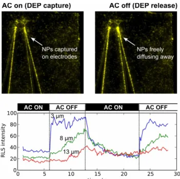
At frequencies above 400 kHz, this bulk fluid motion dies out and only 'pure' positive dielectrophoresis is observed with particles concentrating onto the electrodes when AC is switched on. When the electric field is then turned off, the particles re-diffuse away from the electrodes, which becomes especially apparent when analyzing the scattered light intensity as a function of time at different distances from the electrodes (Fig. 12).
Fig. 12. Dielectrophoresis of gold nanoparticles. Field frequency 1 MHz, amplitude 20 Vpp, electrode separation 10 µm. Bottom: evolution of the light scattering intensity at various distances from the rightmost electrode in the image, demonstrating the occurrence of 'waves' of particles when captured nanoparticles are released from the electrodes upon switching of the DEP force.
B. Simulations
In order to shed more light on the experimental observations, we performed a finite element simulation (COMSOL Multiphysics) with electrodes having 10 µm gaps and positioned at the bottom of a 180 µm large and 100 µm high microchannel. The conductivity of the medium was set to 2 mS/m, and voltage was set to 20 Vpp with the frequency being either 1 MHz or 100
kHz. The calculated electric field and the resulting DEP force field are visualized in Fig. 13.
Fig. 13. Top: Calculated electrical field in a cross section of the PDMS channel (height 100 µm, distance between electrode tips 10 µm). Applied voltages 20 Vpp, conductivity of the medium 2mS, relative
permittivity 80. Bottom: Resulting dielectrophoresis force calculated for 150 nm gold nanoparticles.
The DEP force was calculated from Eq. 1 with rpart = 75 nm
and KCM = 1 (as a result of the high conductivity of the particles
compared to the conductivity of the medium, KCM can be
assumed to be 1). From the distribution of the electrical field, the dielectrophoretic force is calculated. For DEP, the forces are concentrated close to the electrodes and attract the nanoparticles (positive DEP), in agreement with the experimental observations at 1 MHz frequency.
In order to asses the electrothermal origin of the convective movements observed at 100 kHz, the temperature distribution was calculated numerically with finite element analysis using the heat equation, where the heat source term comes from the electrical power dissipated in the medium (conductivity σm):
(Eq. 3)
The electrical field distribution was numerically calculated as before, and now combined with the temperature distribution (Fig. 14). The maximum temperature rise is only 0.2 K, but in view of the micrometric dimensions, the gradient is sufficiently large to induce an orbital fluid flow perpendicularly to the electrode plane.
Fig. 14. Calculated electrothermal temperature rise within the device, in a cross section of the channel (height 100 µm, distance between electrode tips 10 µm). Applied voltage 20 Vpp, conductivity of the
medium 2mS, relative permittivity 80, thermal conductivity of the water 0.55 W m-1 K-1 , heat capacity 4180 J kg-1 K-1. The thermal conductances
of the top layer in PDMS, as well as the substrate in glass are neglected. Temperature is imposed at the electrodes. Bottom: Flow induced within the device due to the electrothermal forces, in a cross section of the channel.
The volumetric electrothermal forces, that point in the direction of the temperature gradient and act directly on the fluid body, were calculated using [89]:
(Eq. 4)
with
where
, and
The coefficients α and β represent the relative changes of permittivity (-0.004 K-1
) and conductivity (0.02 K-1
), respectively, and τ is the charge relaxation time.
We can notice that these electrothermal forces depend on the thermal variation coefficients of both the conductivity and permittivity of the medium. Knowing the electrothermal force distribution, the induced flow velocity can be determined using the Navier-Stokes equation. Results obtained with numerical simulation showed the occurrence of an electrothermal convection cell with a rotating flow above the electrodes, which indicates that electrothermal flow is indeed a plausible explanation for the circular flow patterns observed in our experiments at lower frequencies (100 kHz).
IX. CONCLUSION
The first part of the paper, in which we gave an overview of recent developments of relevance for functionalized plasmonic nanoparticles and their physical and physicochemical behavior in microfluidic systems, demonstrates that fluid mechanical as
well as electrokinetic phenomena offer fascinating opportunities for manipulating and separating colloidal particles. The strong optical response of plasmonic nanoparticle assemblies, in particular their intense resonant light scattering, enables optical tracking and sensing in microsystems using these nano-objects.
We showed for the first time that dark-field light scattering by plasmonic nanoparticles can be used for the imaging and tracking of these particles moving under the influence of an AC electric field. These observations can be further extended by using white light sources in combination with a spectrometer that analyzes the plasmonically scattered light[7], or by combining the images recorded at several wavelengths to obtain hyperspectral imaging[105]. Such spectrally resolved data will give further information on the nature of the AC-induced reversible assembly of the nanoparticles and may develop into novel plasmonic detection schemes.
Further improvements that are currently under investigation are the convergence of optical fiber delivery of localized dark-field illumination with microelectrodes as well as the use of transparent electrodes (see e.g. ref. [106]) to obtain a clearer view of AC-assembled gold nanoparticles currently obscured by the metal electrodes.
REFERENCES
[1] L. Gervais, N. de Rooij, and E. Delamarche, “Microfluidic Chips for Point-of-Care Immunodiagnostics,” Adv. Mater., vol. 23, pp. H151–H176, May 2011.
[2] S. Hayashi and T. Okamoto, “Plasmonics: visit the past to know the future,” J. Phys. D: Appl. Phys, vol. 45, no. 43, p. 433001, Oct. 2012.
[3] P. Zhao, N. Li, and D. Astruc, “State of the art in gold nanoparticle synthesis,” Coord. Chem. Rev., vol. 257, no. 3–4, pp. 638–665, Feb. 2013.
[4] Y. B. Zheng, B. Kiraly, P. S. Weiss, and T. J. Huang, “Molecular plasmonics for biology and nanomedicine.,” Nanomedicine, vol. 7, no. 5, pp. 751–70, May 2012.
[5] B. Veigas, D. Machado, J. Perdigão, I. Portugal, I. Couto, M. Viveiros, and P. V. Baptista, “Au-nanoprobes for detection of SNPs associated with antibiotic resistance in Mycobacterium tuberculosis.,” Nanotechnology, vol. 21, no. 41, art. 415101, Oct. 2010.
[6] J. R. G. Navarro and M. H. V. Werts, “Resonant light scattering spectroscopy of gold, silver and gold-silver alloy nanoparticles and optical detection in microfluidic channels.,” Analyst, vol. 138, pp. 583–592, Nov. 2013.
[7] M. H. V. Werts, V. Raimbault, M. Loumaigne, L. Griscom, O. Français, J. R. G. Navarro, A. Débarre, and B. Le Pioufle, “Optical microscopy and spectroscopy of analyte-sensitive functionalized gold nanoparticles in microfluidic systems,” in Proc. SPIE, 2013, vol. 8595, p. 85950W–85950W–11.
[8] T. M. Squires, R. J. Messinger, and S. R. Manalis, “Making it stick: convection, reaction and diffusion in surface-based biosensors.,” Nat. Biotechnol., vol. 26, no. 4, pp. 417–26, Apr. 2008.
[9] P. E. Sheehan and L. J. Whitman, “Detection limits for nanoscale biosensors.,” Nano Lett., vol. 5, no. 4, pp. 803–7, Apr. 2005. [10] T. Squires and S. Quake, “Microfluidics: Fluid physics at the
nanoliter scale,” Rev. Mod. Phys., vol. 77, no. 3, pp. 977–1026, Jul. 2005.
[11] V. K. K. Upadhyayula, “Functionalized gold nanoparticle supported sensory mechanisms applied in detection of chemical and biological threat agents: a review.,” Anal. Chim. Acta, vol. 715, pp. 1–18, Mar. 2012.
[12] S. S. R. Dasary, U. S. Rai, H. Yu, Y. Anjaneyulu, M. Dubey, and P. C. Ray, “Gold nanoparticle based surface enhanced fluorescence for detection of organophosphorus agents,” Chem. Phys. Lett., vol. 460, no. 1–3, pp. 187–190, Jul. 2008.
[13] H. R. Sim, A. W. Wark, and H. J. Lee, “Attomolar detection of protein biomarkers using biofunctionalized gold nanorods with surface plasmon resonance.,” Analyst, vol. 135, no. 10, pp. 2528–32, Oct. 2010.
[14] S. Kim, J. Lee, S. J. Lee, and H. J. Lee, “Ultra-sensitive detection of IgE using biofunctionalized nanoparticle-enhanced SPR.,”
Talanta, vol. 81, no. 4–5, pp. 1755–9, Jul. 2010.
[15] X. Huang, S. Neretina, and M. A. El-Sayed, “Gold Nanorods: From Synthesis and Properties to Biological and Biomedical Applications,” Adv. Mater., vol. 21, no. 48, pp. 4880–4910, Dec. 2009.
[16] C. Burda, X. Chen, R. Narayanan, and M. A. El-Sayed, “Chemistry and properties of nanocrystals of different shapes.,” Chem. Rev., vol. 105, no. 4, pp. 1025–102, May 2005.
[17] M. Grzelczak, J. Pérez-Juste, P. Mulvaney, and L. M. Liz-Marzán, “Shape control in gold nanoparticle synthesis.,” Chem. Soc. Rev., vol. 37, no. 9, pp. 1783–91, Oct. 2008.
[18] T. Mallat and A. Baiker, “Potential of gold nanoparticles for oxidation in fine chemical synthesis.,” Ann. Rev. Chem. Biomol.
Eng., vol. 3, pp. 11–28, Jan. 2012.
[19] V. Myroshnychenko, J. Rodríguez-Fernández, I. Pastoriza-Santos, A. M. Funston, C. Novo, P. Mulvaney, L. M. Liz-Marzán, and F. J. García de Abajo, “Modelling the optical response of gold nanoparticles.,” Chem. Soc. Rev., vol. 37, no. 9, pp. 1792–805, Oct. 2008.
[20] L. Dykman and N. Khlebtsov, “Gold nanoparticles in biomedical applications: recent advances and perspectives.,” Chem. Soc. Rev., vol. 41, no. 6, pp. 2256–82, Mar. 2012.
[21] L. Y. T. Chou, K. Ming, and W. C. W. Chan, “Strategies for the intracellular delivery of nanoparticles.,” Chem. Soc. Rev., vol. 40, no. 1, pp. 233–45, Jan. 2011.
[22] A. Govorov and H. Richardson, “Generating heat with metal nanoparticles,” Nano Today, vol. 2, no. 1, pp. 30–38, 2007. [23] R. Wilson, “The use of gold nanoparticles in diagnostics and
detection.,” Chem. Soc. Rev., vol. 37, no. 9, pp. 2028–45, Oct. 2008.
[24] R. A. Sperling, P. Rivera Gil, F. Zhang, M. Zanella, and W. J. Parak, “Biological applications of gold nanoparticles.,” Chem.
Soc. Rev., vol. 37, no. 9, pp. 1896–908, Oct. 2008.
[25] D. Kumar, N. Saini, N. Jain, R. Sareen, and V. Pandit, “Gold nanoparticles: an era in bionanotechnology.,” Exp. Opin. Drug
Deliv., vol. 10, no. 3, pp. 397–409, Mar. 2013.
[26] E. S. Day, J. G. Morton, and J. L. West, “Nanoparticles for thermal cancer therapy.,” J. Biomech. Eng., vol. 131, no. 7, art. 074001, Jul. 2009.
[27] E. C. Dreaden, A. M. Alkilany, X. Huang, C. J. Murphy, and M. a El-Sayed, “The golden age: gold nanoparticles for biomedicine.,”
Chem. Soc. Rev., vol. 41, no. 7, pp. 2740–79, Apr. 2012.
[28] E. C. Dreaden, L. A. Austin, M. A. Mackey, and M. A. El-Sayed, “Size matters: gold nanoparticles in targeted cancer drug delivery.,” Therap. Deliv., vol. 3, no. 4, pp. 457–78, May 2012. [29] S. Akhter, M. Z. Ahmad, F. J. Ahmad, G. Storm, and R. J. Kok,
“Gold nanoparticles in theranostic oncology: current state-of-the-art.,” Exp. Opin. Drug Deliv., vol. 9, no. 10, pp. 1225–43, Oct. 2012.
[30] K. T. Butterworth, S. J. McMahon, F. J. Currell, and K. M. Prise, “Physical basis and biological mechanisms of gold nanoparticle radiosensitization.,” Nanoscale, vol. 4, no. 16, pp. 4830–8, Aug. 2012.
[31] F. Xia, X. Zuo, R. Yang, Y. Xiao, D. Kang, A. Vallée-Bélisle, X. Gong, J. D. Yuen, B. B. Y. Hsu, A. J. Heeger, and K. W. Plaxco, “Colorimetric detection of DNA, small molecules, proteins, and ions using unmodified gold nanoparticles and conjugated polyelectrolytes.,” Proc. Natl. Acad. Sci., vol. 107, no. 24, pp. 10837–41, Jun. 2010.
[32] P. Englebienne, “Use of colloidal gold surface plasmon resonance peak shift to infer affinity constants from the interactions between protein antigens and antibodies specific for single or multiple epitopes.,” Analyst, vol. 123, no. 7, pp. 1599–603, Jul. 1998. [33] R. Elghanian, J. J. Storhoff, R. C. Mucic, R. L. Letsinger, and C.
A. Mirkin, “Selective Colorimetric Detection of Polynucleotides Based on the Distance-Dependent Optical Properties of Gold Nanoparticles,” Science, vol. 277, no. 5329, pp. 1078–1081, Aug. 1997.
[34] S. Bidault, F. J. G. De Abajo, and A. Polman, “Plasmon-based nanolenses assembled on a well-defined DNA template.,” J. Am.
Chem. Soc., vol. 130, no. 9, pp. 2750–1, Mar. 2008.
[35] G. Doria, R. Franco, and P. Baptista, “Nanodiagnostics: fast colorimetric method for single nucleotide polymorphism/mutation detection,” IET Nanobiotechnol., pp. 53–57, 2007.
[36] P. V. Baptista, M. Koziol-Montewka, J. Paluch-Oles, G. Doria, and R. Franco, “Gold-nanoparticle-probe-based assay for rapid and
direct detection of Mycobacterium tuberculosis DNA in clinical samples.,” Clin. Chem., vol. 52, no. 7, pp. 1433–4, Jul. 2006. [37] J. Conde, J. M. de la Fuente, and P. V. Baptista, “RNA
quantification using gold nanoprobes - application to cancer diagnostics.,” J. Nanobiotechnol., vol. 8, art. 5, Jan. 2010. [38] K. Aslan, C. C. Luhrs, and V. H. Pérez-Luna, “Controlled and
Reversible Aggregation of Biotinylated Gold Nanoparticles with Streptavidin,” J. Phys. Chem. B, vol. 108, no. 40, pp. 15631–15639, Oct. 2004.
[39] P. Englebienne, “Use of colloidal gold surface plasmon resonance peak shift to infer affinity constants from the interactions between protein antigens and antibodies specific for single or multiple epitopes.,” Analyst, vol. 123, no. 7, pp. 1599–1603, Jul. 1998. [40] J. R. Kalluri, T. Arbneshi, S. A. Khan, A. Neely, P. Candice, B.
Varisli, M. Washington, S. McAfee, B. Robinson, S. Banerjee, A. K. Singh, D. Senapati, and P. C. Ray, “Use of gold nanoparticles in a simple colorimetric and ultrasensitive dynamic light scattering assay: selective detection of arsenic in groundwater.,” Angew.
Chem. Int. Ed., vol. 48, no. 51, pp. 9668–71, Jan. 2009.
[41] K. Ai, Y. Liu, and L. Lu, “Hydrogen-bonding recognition-induced color change of gold nanoparticles for visual detection of melamine in raw milk and infant formula.,” J. Am. Chem. Soc., vol. 131, no. 27, pp. 9496–7, Jul. 2009.
[42] C. Han and H. Li, “Visual detection of melamine in infant formula at 0.1 ppm level based on silver nanoparticles.,” Analyst, vol. 135, no. 3, pp. 583–8, Mar. 2010.
[43] D. Bartczak, O. L. Muskens, S. Nitti, T. Sanchez-Elsner, T. M. Millar, and A. G. Kanaras, “Interactions of human endothelial cells with gold nanoparticles of different morphologies.,” Small, vol. 8, no. 1, pp. 122–130, Jan. 2012.
[44] J. Yguerabide and E. E. Yguerabide, “Light-scattering submicroscopic particles as highly fluorescent analogs and their use as tracer labels in clinical and biological applications. I. Theory,” Anal. Biochem., vol. 262, no. 2, pp. 137–156, Sep. 1998. [45] J. Yguerabide and E. E. Yguerabide, “Light-scattering
submicroscopic particles as highly fluorescent analogs and their use as tracer labels in clinical and biological applications. II. Experimental characterization,” Anal. Biochem., vol. 262, no. 2, pp. 157–176, Sep. 1998.
[46] J. Yguerabide and E. E. Yguerabide, “Resonance light scattering particles as ultrasensitive labels for detection of analytes in a wide range of applications,” J. Cell. Biochem., vol. 84, no. S37, pp. 71–81, 2001.
[47] T. Mappes, N. Jahr, A. Csaki, N. Vogler, J. Popp, and W. Fritzsche, “The invention of immersion Ultramicroscopy in 1912 - The birth of nanotechnology?,” Angew. Chem. Int. Ed., vol. 51, pp. 11208–11212, Oct. 2012.
[48] R. A. Zsigmondy, “Properties of colloids (Nobel lecture),” Properties of colloids (Nobel lecture), 1926.
[49] M. H. V. Werts, H. Zaim, and M. Blanchard-Desce, “Excimer probe of the binding of alkyl disulfides to gold nanoparticles and subsequent monolayer dynamics.,” Photochem. Photobiol. Sci., vol. 3, no. 1, pp. 29–32, Jan. 2004.
[50] M. Loumaigne, R. Praho, D. Nutarelli, M. H. V. Werts, and A. Débarre, “Fluorescence correlation spectroscopy reveals strong fluorescence quenching of FITC adducts on PEGylated gold nanoparticles in water and the presence of fluorescent aggregates of desorbed thiolate ligands.,” Phys. Chem. Chem. Phys., vol. 12, no. 36, pp. 11004–14, Sep. 2010.
[51] N. Nerambourg, R. Praho, M. H. V. Werts, D. Thomas, and M. Blanchard-Desce, “Hydrophilic monolayer-protected gold nanoparticles and their functionalisation with fluorescent chromophores,” Int. J. Nanotechnol., vol. 5, p. 722–740, 2008. [52] G. Schneider, G. Decher, N. Nerambourg, R. Praho, M. H. V.
Werts, and M. Blanchard-Desce, “Distance-dependent fluorescence quenching on gold nanoparticles ensheathed with layer-by-layer assembled polyelectrolytes.,” Nano Lett., vol. 6, no. 3, pp. 530–6, Mar. 2006.
[53] J. P. Lafleur, S. Senkbeil, T. G. Jensen, and J. P. Kutter, “Gold nanoparticle-based optical microfluidic sensors for analysis of environmental pollutants.,” Lab Chip, vol. 12, no. 22, pp. 4651–6, Nov. 2012.
[54] L. Tong, M. Righini, M. Gonzalez, R. Quidant, and M. Kall, “Optical aggregation of metal nanoparticles in a microfluidic channel for surface-enhanced Raman scattering analysis,” Lab
Chip, vol. 9, no. 2, pp. 193–195, 2009.
[55] C. Delhaye, J.-L. Bruneel, D. Talaga, M. Guirardel, S. Lecomte, and L. Servant, “Tailoring Surface-Enhanced Raman Scattering
Effect Using Microfluidics,” J. Phys. Chem. C, vol. 116, no. 9, pp. 5327–5332, Mar. 2012.
[56] M. H. V. Werts, V. Raimbault, R. Texier-Picard, R. Poizat, O. Français, L. Griscom, and J. R. G. Navarro, “Quantitative full-colour transmitted light microscopy and dyes for concentration mapping and measurement of diffusion coefficients in microfluidic architectures,” Lab Chip, vol. 12, pp. 808–820, 2012.
[57] B. Ibarlucea, C. Díez-Gil, I. Ratera, J. Veciana, A. Caballero, F. Zapata, A. Tárraga, P. Molina, S. Demming, S. Büttgenbach, C. Fernández-Sánchez, and A. Llobera, “PDMS based photonic lab-on-a-chip for the selective optical detection of heavy metal ions.,” Analyst, vol. 138, no. 3, pp. 839–44, Feb. 2013.
[58] F. Lin, M. Sabri, and J. Alirezaie, “Development of a nanoparticle-labeled microfluidic immunoassay for detection of pathogenic microorganisms,” Clin. Diag. Lab. Immunol., vol. 12, no. 3, pp. 418–425, 2005.
[59] V. Filipe, A. Hawe, and W. Jiskoot, “Critical evaluation of Nanoparticle Tracking Analysis (NTA) by NanoSight for the measurement of nanoparticles and protein aggregates.,” Pharm.
Res., vol. 27, no. 5, pp. 796–810, May 2010.
[60] H. Zhu, S. Mavandadi, A. F. Coskun, O. Yaglidere, and A. Ozcan, “Optofluidic fluorescent imaging cytometry on a cell phone.,”
Anal. Chem., vol. 83, no. 17, pp. 6641–7, Sep. 2011.
[61] J. Seo and L. P. Lee, “Disposable integrated microfluidics with self-aligned planar microlenses,” Sens. Actuators B: Chem., vol. 99, no. 2–3, pp. 615–622, May 2004.
[62] A. Y. Fu, C. Spence, A. Scherer, F. H. Arnold, and S. R. Quake, “A microfabricated fluorescence-activated cell sorter.,” Nat.
Biotechnol., vol. 17, no. 11, pp. 1109–11, Nov. 1999.
[63] S. Gawad, L. Schild, and P. H. Renaud, “Micromachined impedance spectroscopy flow cytometer for cell analysis and particle sizing.,” Lab Chip, vol. 1, no. 1, pp. 76–82, Sep. 2001. [64] A. Lenshof and T. Laurell, “Continuous separation of cells and
particles in microfluidic systems.,” Chem. Soc. Rev., vol. 39, no. 3, pp. 1203–17, Mar. 2010.
[65] B. H. Weigl and P. Yager, “Microfluidic Diffusion-Based Separation and Detection,” Science, vol. 283, no. 5400, pp. 346–347, Jan. 1999.
[66] D. W. Inglis, J. A. Davis, R. H. Austin, and J. C. Sturm, “Critical particle size for fractionation by deterministic lateral displacement.,” Lab Chip, vol. 6, no. 5, pp. 655–8, May 2006. [67] L. R. Huang, E. C. Cox, R. H. Austin and J. C. Sturm, “Continuous
Particle Separation Through Deterministic Lateral Displacement.,”
Science, vol. 304 no. 5673 pp. 987-990, May 2004
[68] L. Huang, P. Silberzan, J. Tegenfeldt, E. Cox, J. Sturm, R. Austin, and H. Craighead, “Role of Molecular Size in Ratchet Fractionation,” Phys. Rev. Lett., vol. 89, no. 17, p. 178301, Oct. 2002.
[69] T. Duke and R. Austin, “Microfabricated Sieve for the Continuous Sorting of Macromolecules,” Phys. Rev. Lett., vol. 80, no. 7, pp. 1552–1555, Feb. 1998.
[70] A. A. S. Bhagat, S. S. Kuntaegowdanahalli, and I. Papautsky, “Continuous particle separation in spiral microchannels using Dean flows and differential migration.,” Lab Chip, vol. 8, no. 11, pp. 1906–14, Nov. 2008.
[71] D. Di Carlo, “Inertial microfluidics.,” Lab Chip, vol. 9, no. 21, pp. 3038–46, Nov. 2009.
[72] D. Di Carlo, D. Irimia, R. G. Tompkins, and M. Toner, “Continuous inertial focusing, ordering, and separation of particles in microchannels.,” Proc. Natl. Acad. Sci., vol. 104, no. 48, pp. 18892–7, Nov. 2007.
[73] X. Xuan, J. Zhu, and C. Church, “Particle focusing in microfluidic devices,” Microfluid. Nanofluid., vol. 9, no. 1, pp. 1–16, Mar. 2010.
[74] K. Khoshmanesh, S. Nahavandi, S. Baratchi, A. Mitchell, and K. Kalantar-zadeh, “Dielectrophoretic platforms for bio-microfluidic systems.,” Biosens. Bioelectron., vol. 26, no. 5, pp. 1800–14, Jan. 2011.
[75] E. Bisceglia, M. Cubizolles, F. Mallard, F. Vinet, O. Français, and B. Le Pioufle, “Micro-organism extraction from biological samples using DEP forces enhanced by osmotic shock.,” Lab Chip, vol. 13, no. 5, pp. 901–9, Mar. 2013.
[76] F. S. Hamdi, O. Français, F. Subra, E. Dufour-Gergam, and B. Le Pioufle, “Microarray of non-connected gold pads used as high density electric traps for parallelized pairing and fusion of cells,”
Biomicrofluidics, vol. 7, no. 4, art. 044101, 2013.
[77] J. Regtmeier, R. Eichhorn, M. Viefhues, L. Bogunovic, and D. Anselmetti, “Electrodeless dielectrophoresis for bioanalysis:
theory, devices and applications.,” Electrophoresis, vol. 32, no. 17, pp. 2253–73, Sep. 2011.
[78] T. Honegger, K. Berton, E. Picard, and D. Peyrade, “Determination of Clausius–Mossotti factors and surface capacitances for colloidal particles,” Appl. Phys. Lett., vol. 98, no. 18, p. 181906, 2011. [79] P. Gascoyne, C. Mahidol, M. Ruchirawat, J. Satayavivad, P.
Watcharasit, and F. F. Becker, “Microsample preparation by dielectrophoresis: isolation of malaria.,” Lab Chip, vol. 2, no. 2, pp. 70–5, May 2002.
[80] T. Braschler, N. Demierre, E. Nascimento, T. Silva, A. G. Oliva, and P. Renaud, “Continuous separation of cells by balanced dielectrophoretic forces at multiple frequencies.,” Lab Chip, vol. 8, no. 2, pp. 280–6, Feb. 2008.
[81] H. Li and R. Bashir, “Dielectrophoretic separation and manipulation of live and heat-treated cells of Listeria on microfabricated devices with interdigitated electrodes,” Sens.
Actuators B: Chem., vol. 86, pp. 215–221, 2002.
[82] L. Zheng, J. P. Brody, and P. J. Burke, “Electronic manipulation of DNA, proteins, and nanoparticles for potential circuit assembly.,”
Biosens. Bioelectron., vol. 20, no. 3, pp. 606–19, Oct. 2004.
[83] R. J. Barsotti, M. D. Vahey, R. Wartena, Y.-M. Chiang, J. Voldman, and F. Stellacci, “Assembly of metal nanoparticles into nanogaps.,” Small, vol. 3, no. 3, pp. 488–99, Mar. 2007.
[84] A. F. Chrimes, A. A. Kayani, K. Khoshmanesh, P. R. Stoddart, P. Mulvaney, A. Mitchell, and K. Kalantar-Zadeh, “Dielectrophoresis-Raman spectroscopy system for analysing suspended nanoparticles.,” Lab Chip, vol. 11, no. 5, pp. 921–8, Mar. 2011.
[85] A. Sonnenberg, J. Y. Marciniak, R. Krishnan, and M. J. Heller, “Dielectrophoretic isolation of DNA and nanoparticles from blood.,” Electrophoresis, vol. 33, no. 16, pp. 2482–90, Aug. 2012. [86] R. Tornay, T. Braschler, N. Demierre, B. Steitz, A. Finka, H.
Hofmann, J. A. Hubbell, and P. Renaud, “Dielectrophoresis-based particle exchanger for the manipulation and surface functionalization of particles.,” Lab Chip, vol. 8, no. 2, pp. 267–73, Feb. 2008.
[87] A. Ramos, H. Morgan, N. G. Green, and A. Castellanos, “Ac electrokinetics: a review of forces in microelectrode structures,” J. Phys. D: Appl. Phys, vol. 31, no. 18, pp. 2338–2353, Sep. 1998. [88] A. Castellanos and A. Ramos, “Electrohydrodynamics and
dielectrophoresis in microsystems: scaling laws,” J. Phys. D: Appl.
Phys, vol. 36, pp. 2584-2597, 2003.
[89] J. Oh, R. Hart, J. Capurro, and H. M. Noh, “Comprehensive analysis of particle motion under non-uniform AC electric fields in a microchannel.,” Lab Chip, vol. 9, no. 1, pp. 62–78, Jan. 2009. [90] W. D. Geoghegan, “An electrophoretic method for selection of
conditions for production of electrophoretically uniform protein colloidal gold complexes.,” J. Histochem. Cytochem., vol. 39, no. 1, pp. 111–21, Jan. 1991.
[91] C. De Roe, P. J. Courtoy, and P. Baudhuin, “A model of protein-colloidal gold interactions.,” J. Histochem. Cytochem., vol. 35, no. 11, pp. 1191–1198, Nov. 1987.
[92] C. D. Walkey and W. C. W. Chan, “Understanding and controlling the interaction of nanomaterials with proteins in a physiological environment.,” Chem. Soc. Rev., no. 7, Nov. 2011.
[93] C. Mangeney, F. Ferrage, I. Aujard, V. Marchi-Artzner, L. Jullien, O. Ouari, E. D. Rékaï, A. Laschewsky, I. Vikholm, and J. W. Sadowski, “Synthesis and properties of water-soluble gold colloids covalently derivatized with neutral polymer monolayers.,” J. Am.
Chem. Soc., vol. 124, no. 20, pp. 5811–21, May 2002.
[94] G. Schneider, G. Decher, N. Nerambourg, R. Praho, M. H. V Werts, and M. Blanchard-Desce, “Distance-dependent fluorescence quenching on gold nanoparticles ensheathed with layer-by-layer assembled polyelectrolytes.,” Nano Lett., vol. 6, no. 3, pp. 530–6, Mar. 2006.
[95] J. C. Love, L. A. Estroff, J. K. Kriebel, R. G. Nuzzo, and G. M. Whitesides, “Self-assembled monolayers of thiolates on metals as a form of nanotechnology.,” Chem. Rev., vol. 105, no. 4, pp. 1103–69, Apr. 2005.
[96] M. Brust, J. Fink, and D. Bethell, “Synthesis and reactions of functionalised gold nanoparticles,” J. Chem. Soc., Chem.
Commun., pp. 1655–1656, 1995.
[97] J. R. G. Navarro, M. Plugge, M. Loumaigne, A. Sanchez-Gonzalez, B. Mennucci, A. Débarre, A. M. Brouwer, and M. H. V. Werts, “Probing the interactions between disulfide-based ligands and gold nanoparticles using a functionalised fluorescent perylene-monoimide dye.,” Photochem. Photobiol. Sci., vol. 9, no. 7, pp. 1042–54, Jul. 2010.