HAL Id: insu-03018692
https://hal-insu.archives-ouvertes.fr/insu-03018692
Submitted on 23 Nov 2020
HAL is a multi-disciplinary open access
archive for the deposit and dissemination of
sci-entific research documents, whether they are
pub-lished or not. The documents may come from
teaching and research institutions in France or
abroad, or from public or private research centers.
L’archive ouverte pluridisciplinaire HAL, est
destinée au dépôt et à la diffusion de documents
scientifiques de niveau recherche, publiés ou non,
émanant des établissements d’enseignement et de
recherche français ou étrangers, des laboratoires
publics ou privés.
Propagation characteristics of auroral kilometric
radiation observed by the MEMO experiment on
Interball 2
Michel Parrot, François Lefeuvre, Jean-Louis Rauch, Ondřej Santolík, M.M.
Mogilevski
To cite this version:
Michel Parrot, François Lefeuvre, Jean-Louis Rauch, Ondřej Santolík, M.M. Mogilevski.
Propaga-tion characteristics of auroral kilometric radiaPropaga-tion observed by the MEMO experiment on Interball
2. Journal of Geophysical Research Space Physics, American Geophysical Union/Wiley, 2001, 106,
pp.315-325. �insu-03018692�
JOURNAL OF GEOPHYSICAL RESEARCH, VOL. 106, NO. A1, PAGES 315-325, JANUARY 1, 2001
Propagation characteristics of auroral kilometric radiation
observed by the MEMO experiment on Interball 2
M. Parrot, F. Lefeuvre, and J. L. Rauch
Laboratoire de Physique et Chimie de l'Environnement, Centre National de la Recherche Scientifique Orleans, France
O. S antolik
Faculty of Mathematics and Physics, Charles University, Prague M. M. Mogilevski
Space Research Institute, Russian Academy of Sciences, Moscow
Abstract. The MEMO experiment is a part of the Interball 2 wave consortium. It is
connected to a total of six electric and nine magnetic independent sensors. It provides
waveforms associated with the measurement of two to five components in the thr•
frequency bands: ELF (5-1000 Hz), VLF (1-20 kHz), and LF (20-250 kHz). Waveforms
of thr• magnetic components and one electric component recorded during observations
of auroral kilometric radiation (AKR) allow a detailed study of the characteristics of
these emissions. In particular, the wave normal directions of AKR relative to the Earth's
magnetic field are determined using several methods: the classical methods based on the
plane wave approximation [Means, 1972] and the wave distribution function method
which represents the evaluation of the wave energy density distribution with respect to
the angular frequency and the wave normal direction(s). One event is fully analyzed in
this paper. It is shown that AKR propagates with a polarization quasi-circular (ellipticity
value- 0.9), a right polarization (i.e., R-X mode), and wave normals weakly oblique (-
300).
1. Introduction
This paper deals with the determination of wave normal directions in the frequency fine structure of auroral kilometric radiation (AKR) observed on the Interball 2
satellite. It is based on the simultaneous measurements of the
three magnetic wave field components and of one electric
field component.
It completes
a preliminary
paper from
Lefeuvre et al. [1998] where analyses of Interball 2 data were
based on the plane wave hypothesis.
Several wave analysis techniques have been used to
determine the wave normal directions of auroral kilometric
radiations.
The first measurements
of the propagation
characteristics were obtained by using occultations of the
emission by the moon [Alexander and Kaiser, 1976; Kaiser
and Alexander,
1976].
Under
the assumption
of a purely
transverse electromagnetic wave, estimates of the direction
have been derived from the spin-null method, that is, from
the modulation ofthe signal associated with the measurement
of one electric field component [Gurnett, 1974; Kurth et al.,
Copyright 2001 by the American Geophysical Union.
Paper number 2000JA900072. 0148-0227/01/2000 JA900072509.00
1975; Kaiser and Stone, 1975; Kaiser et al., 1978; James,
1980;
Mellot et al., 1984;
Calvert
and Hashimoto,
1990;
Hilgers
et al., 1992a].
A more
precise
estimation,
based
on
the change
of the
relative
phase
of the signals
received
by
two orthogonal antennas during a spin revolution, has been
proposed
by Calvert
[1985].
It has
also
been
used
by Mellott
et al. [1985, 1986] and Huff et al. [1988]. Now all these
methods
assume
that
the observed
wave
behaves
as a plane
wave.
Moreover,
they
have
a weak
time
resolution
(the
spin
period
at least)
and depend
on the relative
positions
of the
spin axis, the Earth's magnetic field direction, and the wave
vector.
The situation
is much
better
when
one
measures
a larger
number
of field
components.
Morioka
et al. [1990]
used
five-
component measurement of the Akebono satellite to calculate
the Poynting flux vector in the satellite frame. With onboard
narrow-band receivers they studied phase relations between
the field components in a band of 100 Hz inside an AKR
emission. The Interball 2 satellite also allows the
measurement
of several
components.
The computation
bythe
POLRAD experiment
[Hanasz
et al., 1998] of the nine
Stokes parameters of the three electric wave field
components allows the full determination of the wave normal
directions
in a fraction
of a second.
The only
hypothesis
that
316 PARROT ET AL.' PROPAGATION CHARACTERISTICS OF AKR 2.667e+05 _t 2.133e+05 1.600e+05 1.067e+05
5.333e+04
- '11!•
•
0.000 -0 1805 TIME 19:52:20:083 20:08:54:465 20:25:28:426 20:42:04:390 21:08:24:049 21:24:58:416 MLTTIME 20.67 21.27 21.73 22.10 22.56 22.81 GEO LONG 356.91 3.93 9.09 12.78 16.55 18.08 INVLAT 76.28 74.89 73.25 71.42 68.00 65.46 ALTITUDE 18532 19025 19175 18986 17975 18878Plate 1. AKR event recorded by MEMO on January 28, 1997, with an electric sensor. The spectrogram
starts at 1952:20 UT and ends at 2124:58 UT. The other parameters are the magnetic local time, the
geographic longitude, the invariant latitude, and the altitude of the satellite. It must be noted that regular
gaps without data have been suppressed
in order
to produce
a continuous
plot. Read 2.667e+05
as
2.667x10⁵. 0.000 ', .... , TIME 20:37:23:580 20:37:23:773 20:52:19:600 20:52:19:793 21:07:15:609 21:07:15:802 MLT TIME 22.00 22.00 22.29 22.29 22.55 22.55 GEO LONG 11.87 11.87 14.49 14.49 18.43 16.43 INV LAT 71.95 71.95 70.17 70.17 88.17 68.17 ALTITUDE 19074 19074 18698 18698 18037 18037 3.257 2.584 1.911 1.239 0.5657 -0.1071
Plate 2. Spectrogram representation of three bursts extracted from the event of Plate 1 at 2037:23, 2052:19,
and 2107:15. The duration of each burst is 0.32 s, and the frequency is limited to 160 kHz. The parameters
PARROT ET AL.' PROPAGATION CHARACTERISTICS OF AKR 317
(o)
!.õ07a+05' •.430e-t-04
3.215e+04-0
000
,i
(b)
1.288e + 0,5 • g.a45e+ 1:)4 • 6.430e+ 04 3.215e+0• 0.000(c)
1.807e+05'i
- '-
... ß
-, -. •-., • •...
' ...
'•3.•, -•. - 1.88•e+05 • g.645e+04 • S.430e+04 ]- ß .•...- _- 3215e+ 04 .. 0.000 • • 20:37:23:5õ0 20:37:P.3:773 20:52: I g:•lO0 MLT THeE 22.00 I•.00 22.29 GEO LONG 11.87 l 1.87 14.49 ]NV I.AT 7t.g5 71.95 70.17 ALTITUDE 19074 19074 1869B 20:52: t 9:793 21:07:15:609 21:07:15:B02 22.29 22.55 22.55 14.49 16.43 10.43 70. t? 68.17 68.17 18896 18037 18037 o v o 0.8•0 0.8000 0.4•0 0.2000 0.8•0 O.B•O 0.4000 0.2•0 0.5000Plate 3. For the data shown
in Plate
2: (a) a spectrogram
representing
the degree
of polarization,
(b) a
spectrogram representing the wave ellipticity, and (c) a spectrogram representing the sense ofpolarization.
318 PARROT ET AL.' PROPAGATION CHARACTERISTICS OF AKR l.•07e+Oõ 1.288e + 0{5 3:g.•4õe+04
i •.4.,30e+04
3.815e+04 0.000(b)
I 607e+05 1.288e+05 =:: g. B45e+04 :• . g' 6.430e+04 - ' - K ' "* 3.21õe+04 . o ooo tis
I •,..,.
"ll I..,.n
ß • 2.•0:37:23:õ80 20:39:23:7'73 20:õ2:19:BOO 20:õ2: t g:Tg'3 •LT TIME 22.00 2.00 21L29 22.29 (IEO LONG 11.87 11.87 14.49 14.49 INV LAT 71.g5 71.gõ 70.17 70.17 M•,TITUD g 1 gO 74 19074 186 g 8 18698 :07:16:609 21:07:15:80• 16.43 16.43 68.17 68.17 16037 16037 180.0 108.0 380.0 2.88.0 216.0 144.0 71/.00Plate 4. For the data shown in Plate 2: (a) a spectrogram representing the 0 angle, and (b) a spectrogram
PARROT ET AL.: PROPAGATION CHARACTERISTICS OF AKR 319
has to be made is that the wave is a plane wave. The
transmission to the ground by the MEMO experiment
[Lefeuvre etal., 1998] of the waveforms of four wave field
components (one electric and three magnetic) give still
greater facilities. In their publication on preliminary results,
Lefeuvre etal. have shown how classical methods of
direction findings could be used to determine the wave
normal direction under the plane wave hypothesis. But such
an hypothesis is not compulsory. It is the objective of the
present paper to show how the plane wave hypothesis may be
tested and how non plane waves may be analyzed.
The use of high-resolution methods is particularly needed
to analyze AKR temporal fine structures, lasting a few
seconds or less, which have been pointed out by numerous
authors [Gurnett et al., 1979; Gurnett and Anderson, 1981;
Benson et al., 1988]. They are associated with particle
acceleration structures [de Feraudy et al., 1988; Louarn et
al., 1990; Ungstrup etal., 1990; Hilgers etal., 1991, 1992b;
Pottelette et al., 1992]. On the other hand, fine, narrow
bandwidth, drifting structures (< 1 kHz), with rapidly varying
center frequencies, have been observed [Gurnett et al., 1979;
Gurnett and Anderson, 1981; Morioka et al., 1981; Baumback and Calvert, 1987; Benson etal., 1988].
However, most theories proposed for AKR assume that the
plasma is homogeneous and do not take into account the
existence of fine structures. Observations have been
explained in terms of a movement of the AKR source region
along magnetic field lines [Gurnett et al., 1979; Gurnett and
Anderson, 1981 ]. Maser emissions in non-uniform magnetic fields have been studied [Le Qudau et al., 1985; Zarka et al.,
1986; Le Qudau and Louarn, 1989]. A nonlinear theory of
radiation from the interaction between lower hybrid solirons
and upper hybrid waves has been developed [Pottelette et al.,
1992]. But none of the proposed interpretations has been
confirmed. Non-ambiguous determinations of the
polarization
characteristics
within these structures
and
measurements of the phase relationships between different
frequency
bands
may provide
key parameters
for the
generation mechanisms.
Section 2 will present the wave analysis methods we used
to determine the propagation characteristics of AKR. The
analysis
of an AKR event
is presented
in section
3, whereas
discussion and conclusions are given in section 4.
2. Wave Analysis Methods
Various methods are used to determine wave characteristics
in this study.
The wave normal
direction
of the waves
is
calculated when the magnetic component frame istransformed in an orthogonal frame of reference linked to the
Earth's magnetic field B0: the z axis lies along B0, the x axis
points
toward
the
direction
of decreasing
magnetic
latitude
in
the local magnetic meridian plane, and the y axis completes
the orthogonal
set.
In this system
the wave
normal
direction
k is characterized by thepolar angle 0 and the azimuthal angle
q). Three independent
plane wave methods
are used
to
determine the k direction (only one is used in this paper).
They give correct values only when the plane wave
approximation is valid. We used the method of Means [1972]
which is based on the imaginary part of the spectral matrix.
The determination of the sense of polarization for quasi-
parallel waves is based on the sign of the imaginary part of
the cross spectrum between thex and y components [Lefeuvre
et al., 1986]. If this sign is positive, the waves are right-hand
polarized; if it is negative, the waves are left-hand polarized.
The degree of polarization is directly estimated from the
spectral matrix of the three magnetic components. Under the
plane wave hypothesis the ellipticity is estimated from the
eigenvector associated with the non null eigenvalue in the
plane wave hypothesis [Samson and Olson, 1980].
When the assumption of a plane wave is not valid, the
determination of the wave distribution function (WDF) is
required. The WDF specifies the distribution of wave energy
density with respect to the frequency and the wave normal
direction [Storey andLefeuvre, 1974, 1979, 1980]. Examples
of wave analysis with WDF are given by Lefeuvre and
Delannoy [1979], Parrot and Lefeuvre [1986], and Lefeuvre
et al. [1992]. For the WDF treatment we need to know the
plasma frequency and the electron gyrofrequency.
For the Means' method the WDF is able to remove the
ambiguity of the direction of wave propagation (in the
direction of B0 or opposite) when at least one electric
component is used. But this electric component and the
magnetic components must be in the same frame of reference
[see, e.g., Santolik and Parrot, 1999].
3. Propagation Characteristics of an AKR Event
3.1. Data
The MEMO experiment is a part of the wave experiment
consortium onboard the satellite Interball 2 which was
launched into an elliptical orbit on September 6, 1996, with
an inclination of 65 degrees, an apogee altitude of 19,200 km,
and a perigee altitude of 772 km. A full description of the
experiment is given by Lefeuvre et al. [1998]. MEMO is
connected to a total of six electric and nine magnetic sensors
working in three different frequency ranges: ELF (5-1000
I-Iz), VLF (1-20 kI-Iz), and LF (20-250 kHz). There are two
operating modes: a survey mode with low-resolution data in
order to provide an overview of the measured wave
phenomena, and a burst mode where the waveforms of the
three magnetic components and one electric component are
recorded for short time intervals. The spectrogram in the
bottom panel of Plate 1 represents one AKR event recorded
by MEMO on January 28, 1997, using the survey mode. It
shows data from an electric component in the LF range up to
266.7 kI-Iz for a period of nearly I hour and 30 min. The
intensity is color coded according to the scale on the right and
the geophysical parameters are given at the bottom. It is a
night pass
at high invariant
latitude
(650-76
ø
) around
the
satellite apogee. Fine, narrow bandwidth, drifting structures
appear from 100 up to 250 kHz. Strong AKR emissions with
a low-frequency part down to ~ 40 kHz can be observed at the
beginning, and between 2029 and 2123 UT. During this
320 PARROT ET AL.: PROPAGATION CHARACTERISTICS OF AKR
recorded in the burst mode, and their spectrograms are given
in Plate 2. The three spectrograms are recorded at 2037:23,
2052:19, and 2107:15, respectively, and their duration is 0.32
s. For the analysis they are limited in frequency to 160 kHz
because the data for the magnetic components are corrupted
by interference at higher frequencies. The middle spectrogram
does not display any particular features because there is a
small gap in AKR activity. In the first panel a large AKR
frequency band is seen between 70 and 100 kHz, whereas in the third panel, temporal fine structures are found to occur at frequencies starting as low as 32 kHz. The emissions below
the white line which represents the electron gyrofrequency
have no meaning due to the low-frequency cutoff of the
MEMO HF filter.
3.2. Propagation Characteristics
3.2.1. Plane wave analysis. The analysis described in section 2 has been applied to the magnetic data which
correspond to the spectrograms shown in Plate 2. Time-
frequency plots of different parameters are collected in Plate
3. Plate 3a shows the degree of polarization. From this plot
we can get information for a given frequency and time similarly as in the spectrogram of Plate 2. According to the color scale on the right, the degree of polarization is coded
between blue (0) and red (1). White represents the regions of
low signal intensity where the magnetic power-spectral
density
is lower
than
4x 10
'4 m¾2/Hz.
We see
in the
first
panel
that the emission observed around 80 kHz tends to have ahigh degree ofpolarization. The emissions ofhighest intensity
are generally well polarized with a polarization degree larger
than 0.75 except at 32 kHz in the third panel. This low
polarization degree indicates that the assumption of a single
plane wave is certainly not valid in this case.
The ellipticity of the wave polarization is given in Plate 3b
and coded between blue (linear polarization) and red (circular
polarization). In the first panel the ellipticity around 80 kHz
is often between 0.75 and 1, which indicates that the polarization is practically circular, whereas in other cases
nothing can be said when the degree of polarization is low.
For example, in the third panel the emissions at 32 and 159
kHz have an ellipticity value around 0.5 which indicates a non
well-determined polarization.
Information about the wave polarization is extended in Plate
3c. The sense of polarization in the plane perpendicular to B0
is indicated by red or green spots. It is obviously undefined
when the polarization is linear. Plate 3c indicates that the
more intense emissions (the large band emission in the first
panel and the fine structures in the third panel) are right-hand
polarized.
The wave normal directions are given in Plates 4a and 4b
where the two angles 0 and q) are represented according to the
color scale on the right, respectively. They are obtained with
the Means' method. Plate 4a indicates that waves around 80
kHz in the first and the third panel have practically the same 0 values (-35ø), whereas it is seen in Plate 4b that the angles
q) are different in the two panels and separated approximately
by 180 ø.
3.2.2. WDF analysis. Since we have found that the plane
wave hypothesis is not valid in the spectrograms shown in
Plate 2, we have done a more detailed analysis of the AKR
propagation at various frequencies using the WDF method.
The amount of data recorded during the bursts represented in
Plate 2 allows several different analyses, and the first and the
third data intervals in Plate 2 have been divided into 10 parts.
For all the events, the electron gyrofrequency is -23.5 kHz.
Without a reliable determination of the plasma frequency we
have taken a value of 11 kHz at 2037 UT and a value of 8.5
kHz at 2107 UT. As the estimation mainly relies on the
magnetic components, the results are not sensitive to a
multiplication by0.5 or 2. The assumption ofaR-Xmode and
a cold plasma are used in this analysis. Plate 5 shows the
results of the WDF analysis performed at the beginning and
end of the first burst of data in Plate 2 at time intervals 1 and
10. Four analyses have been made at a frequency of 80 kHz
and each is represented by two polar plots. For example, the
first plot on the left in the first row is related to waves propagating in the direction ofthemagnetic field, whereas the
second plot in the first row is related to the same analysis but
for waves propagating in direction opposite to the magnetic
field. Each plot displays the intensity of the WDF in arbitrary
units as a function of the azimuthal angle 0 and the polar angle q). In these two plots and the two others on the same row it is impossible to distinguish between upgoing and downgoing waves because only the three magnetic components have been used. It is observed that the maximum
of the WDF is centered on 0 = -30 ø and q) = -300 ø. The
energy is not well localized because there is some extension of the WDF maximum in 0 and q). It is noticed that the
analysis performed on the last part (part 10) of the time
interval of the same burst shows similar features concerning the direction and the extension of the WDF. The second row concerns the WDF analysis when we take in addition one electric component. It allows the separation between upgoing and downgoing waves. It is seen that the waves are in the opposite direction of the magnetic field and therefore upgoing as is expected in the Northern Hemisphere where the magnetic field is directed toward the Earth. For the third burst of data, WDF analysis can be performed at different frequencies when the emissions are strong, and Plate 6 displays these results. Three time intervals have been selected
(part 4, 7, and 10) and three frequencies (32.1, 80.7, and
159.2 kHz). The three magnetic plus one electric components
are used. Several important points can be observed: 1. For all the time intervals the WDFs are almost identical
at a given frequency.
2. Moreover, they are identical during all the time intervals
of the burst at the two frequencies 32.1 and 80.7 kHz.
3. The azimuthal angle 0 is nearly identical to the value
observed in the first burst 30 min before.
4. From the first burst to the third the angle q) changes. This
angle is shifted by-180 ø (this is underlined in Plate 7 where
two WDFs analysis at 80 kHz separated by a time interval of
30 min are represented).
5. The WDF at 159.2 kHz presents features which are
PARROT ET AL.' PROPAGATION CHARACTERISTICS OF AKR 321
January 28, 1997, 2037 UT
3B 3B+E part 1 o part 10 oPlate 5. WDF analysis for the first burst of Plate 2 at a frequency equal to 80 kHz (see text for explanation),
January 28, 1997, 2037 UT.
January 28, 1997, 2107 UT
32.1 kHz 80.7 kHz 159.2 kHzpart 4 part 7 part 10
ß ,
Plate 6. WDF analysis for the third burst of Plate 2 at three different frequencies (32.1, 80.7, and 159.2
PARROT ET AL.' PROPAGATION CHARACTERISTICS OF AKR 323
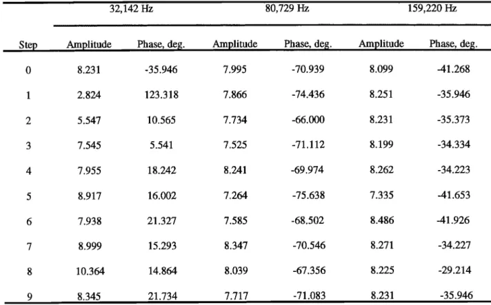
Table 1. Transfer Function of the Electric Component Estimated by the WDF Method at Three Different
Frequencies.
32,142 Hz 80,729 Hz 159,220 Hz
ß _ ... • -•::_- - - - ... •-_-_-_- .... _-___•.-7 ... 7 ... • ... -•-•--- - •-_- ---- - • ... _ --- - - - •--- ...
Ste Am litude
Phase,
deg.
Amplitude
Phase,
de[[.
Amplitude
Phase,
deg.
0 8.231 -35.946 7.995 -70.939 8.099 -41.268 1 2.824 123.318 7.866 -74.436 8.251 -35.946 2 5.547 10.565 7.734 -66.000 8.231 -35.373 3 7.545 5.541 7.525 -71.112 8.199 -34.334 4 7.955 18.242 8.241 -69.974 8.262 -34.223 5 8.917 16.002 7.264 -75.638 7.335 -41.653 6 7.938 21.327 7.585 -68.502 8.486 -41.926 7 8.999 15.293 8.347 -70.546 8.271 -34.227 8 10.364 14. 864 8.039 -67.356 8.225 -29.214 9 8.345 21.734 7.717 -71.083 8.231 -35.946
tO indicate that this emission may have a different origin.
It must be noted that the use of an electric component is
subject to caution. Due to the unknown coupling impedance
between the antenna and the plasma, it is impossible to
correctly evaluate the cross spectra between the electric and
magnetic components. In the analysis shown before, we have
considered the coupling impedance (the phase shift and
amplitude change) of the antenna output with respect to the
wave electric field as an unknown parameter. We have
estimated the WDF together with this parameter, but it is a
AKRpropagates with a polarization that is quasi-circular and
in the R-X mode. The wave normals are weakly oblique at a
wave angle of 30 ø. It is observed that at a given frequency the
characteristics of the emission are rather constant for a long
time interval (30 min). The propagation characteristics are
also similar for emissions which seems dissociated because
they appear at different frequencies. This implies that in our
event the discrete emissions observed at 32.1 and 80.7 kHz
in the third burst probablyhave the same origin. The variation
of q) between 2037 and 2107 UT also suggests that Interball
dangerous process because in fact we change the amplitude of 2 was just above the source region during this time interval.
the electric component. Then we have checked the estimation
on several
parts
of the signal
considering
that
there
is no Acknowledgments.
Michel
Blanc
thanks
Michael
L. Kaiser
and
change
in the
plasma
during
0.32
s. The
results
are
shown
in Wynne
Calvert
for
their
assistance
in evaluating
this
paper.
Table 1. It concerns the 10 parts of data of the third burst at
three different frequencies (32.1, 80.7, and 159.2 kHz). For
each
frequency
the
estimated
phase
and
amplitude
are
given.
References
It is observed that for a given frequency the estimated Alexander, J.K., and M.L. Kaiser, Terrestrial kilometric
amplitude
andphase
areroughly
similar
in all l0 parts
of the
radiation,
1, Spatia!
structurestudies,
J. Geophys.
Res.,81,
signal. This is not true at 32 kHz for the first parts of the time 5948, 1976.
interval because the signal is low (see Plate 2), and then the Baumback, M.M., and W. Calvert, The minimum bandwiths
estimation is not meaningful. of auroral kilometric radiation, Geophys. Res. Lett., 14,
119, 1987.
4. Discussion and Conclusions Benson, R.F., M.M. Mellott, R.L. Huff, and D.A. Gurnett,
Ordinary mode auroral kilometric radiation fine structure
This
paper
describes
the first accurate
determination
of
observed
by DE 1, J. Geophys.
Res.,
93, 7515,
1988.
AKR wave
normal
direction.
Because
of the
high
altitude
of Calvert,
W., DE-1 measurements
of AKR wave
direction,
Interball
2, this
AKR event
is obviously
observed
from
above
Geophys.
Res.
Lett., 12, 381, 1985.
324 PARROT ET AL.: PROPAGATION CHARACTERISTICS OF AKR
propagation properties of auroral kilometric radiation, J. low-altitude hiss: Case studies, J. Geophys. Res., 97,
Geophys. Res., 95, 3943, 1990. 10,601, 1992.
de Feraudy, H., A. Bahnsen, and M. Jesperen, Observation of Lefeuwe, F., M. Parrot, J.L. Rauch, B. Pokier, A. Masson,
nightside and dayside auroral kilometric radiation with
Viking, in Proceedings of 2nd International Workshop on
Radio Emission from Planetary Magnetosphere, edited by
H.O. Rucker, S.J. Bauer, and B.M. Pedersen, p. 239,
Verlag der Osterreichischen Akademie der
Wissenschaften, Vienna, 1988.Gumett, D.A., The Earth as a radio source: Terrestrial
kilometric radiation, J. Geophys. Res., 79, 4227, 1974.
Gumett, D.A., and R.R. Anderson, The kilometric radio
emission spectrum: Relationship to auroral acceleration
processes, in Physics of Auroral Arc Formation, Geophys.
Monogr. $er., vol. 25, edited by $.-I. Akasofu and J.R.
Kan, p. 341, AGU, Washington, D.C., 1981.
Gumett, D.A., R.R. Anderson, F.L. Scarf, R.W. Fredericks,
and M. Mogilevsky, Preliminary results from the MEMO
multicomponentmeasurements of waves on-board Interball
2, Ann. Geophys., 16, 1117, 1998.
Le Qutau, D., and P. Louarn, Analytical study of the
relativistic dispersion: Application to the generation of the
AKR, J. Geophys. Res., 94, 2605, 1989.
Le Qutau, D., R. Pellat, and A. Roux, The maser synchrotron
instability in an inhomogeneous medium: Application to
the generation of auroral kilometric radiation, Ann.
Geophys., 3, 273, 1985.
Louarn, P., A. Roux, H. de Feraudy, D. Le Qutau, M. Andrt,
and L. Matson, Trapped electrons as a free energy source
for the auroral kilometric radiation, J. Geophys. Res., 95,
5983, 1990.
and E.J. Smith, Initial results from the ISEE 1 and 2 Means, J.D., Use of the three-dimensional covariance matrix
plasma waveinvestigation, Space $ci. Rev., 23, 103, 1979.
Hanasz, J., R. Schreiber, H. de Feraudy, M.M. Mogilevsky,
and T.V. Romantsova, Observations of the upper
frequency cutoffs of the auroral kilometric radiation, Ann.
Geophys., 16, 1097, 1998.
Hilgers, A., A. Roux, and R. Lundin, Characteristics of AKR
sources: A statistical description, Geophys. Res. Lett., 18,
1493, 1991.
Hilgers, A., H. de Feraudy, and D. Le Qutau, Measurements
of the E field polarization of AKR inside the sources, J.
Geophys. Res., 97, 8381, 1992a.
Hilgers, A., B. Holback, G. Holmgren, and R. BostrOm, Probe
measurements of low plasma densities with applications to
the auroral acceleration region and auroral kilometric
radiation sources, J. Geophys. Res., 97, 8631, 1992b.
Huff, R.L., W. Calvert, J.D. Craven, L.A. Frank, and D.A.
Gumett, Mapping of auroral kilometric radiation sources
to the aurora, J. Geophys. Res., 93, 11,445, 1988.
James, H.G., Measurements of auroral kilometric radiation
and associated VLF data from ISIS 1, J. Geophys. Res.,
85, 3367, 1980.
Kaiser, M.L., and J.K. Alexander, Source location measurement of terrestrial kilometric radiation obtained
from lunar orbit, Geophys. Res. Lett., 3, 37, 1976.
Kaiser, M.L., and R.G. Stone, Earth as an intense planetary
radio source: Similarities to Jupiter and Saturn, Science,
189, 285, 1975.
Kaiser, M.L., J.K. Alexander, A.C. Riddle, J.B. Pearce, and
J.W. Warwick, Direct measurement byVoyager 1 and 2 of
the polarization of terrestrial kilometric radiation,
Geophys. Res. Lett., 5, 857, 1978.
Kurth, W.S., M.M. Baumback, and D.A. Gurnett, Direction
findings measurement of auroral kilometric radiation, J.
Geophys. Res., 80, 2764, 1975.
Lefeuwe, F., and C. Delannoy, Analysis of random electromagnetic wave field by a maximum entropy
method, Ann. Telecommun., 34, 204, 1979.
Lefeuvre, F., Y. Marouan, M. Parrot, and J.L. Rauch, Rapid
determination of the sense ofpolarization and the sense of
propagation for random electromagnetic fields: Applications to GEOS 1 and AUREOL 3 data, Ann. Geophys., 6, 457, 1986. (Correction, Ann. Geophys.,
5A(4), 252, 1987.)
Lefeuwe, F., J. L. Rauch, D. Lagoutte, J. J. Berthelier, and J. C. Cerisier, Propagation characteristics of dayside
in analyzing the polarization properties of plane waves, J.
Geophys. Res., 77, 5551, 1972.
Mellot, M.M., W. Calvert, R.L. Huff, D.A. Gurnett, and $.D.
Shawban, DE 1 observations of ordinary mode and
extraordinary mode auroral kilometric radiation, Geophys.
Res. Lett., 11, 1188, 1984.
Mellot, M.M., R.L. Huff, and D.A. Gurnett, The auroral
kilometric radiation: DE 1 direction finding studies,
Geophys. Res. Lett., 12, 479, 1985.
Mellot, M.M., R.L. Huff, and D.A. Gurnett, DE 1
observations of harmonic auroral kilometric radiation, J.
Geophys. Res., 91, 13,732, 1986.
Morioka, A., H. Oya, and $. Miyatake, Terrestrial kilometric
radiation observed by the satellite Jikiken, J. Geomagn.
Geoelectr., 33, 37, 1981.
Morioka, A., H. Oya, and K. Kobayashi, Polarization and
mode identiffcation of auroral kilometric radiation by PWS
system onboard the Akebono 0EXOS-D) satellite, J.
Geomagn. Geoelectr., 42, 443, 1990.
Parrot, M., and F. Lefeuwe, Statistical study of the
propagation characteristics of ELF hiss observed on
GEOS-1, outside and inside the plasmasphere, Ann.
Geophys., 4, 363, 1986.
Pottelette, R., R.A. Treumann, and N. Dubouloz, Auroral
kilometric radiation generation from lower hybrid solitons
upper hybrid waves interaction, J. Geophys. Res., 97,
12,029, 1992.
Samson, J.C., and J.V. Olson, Some comments on the
descriptions of the polarization states of waves, Geophys.
J. R. Astron. Soc., 61, 115, 1980.
Santolik, O., and M. Parrot, Case studies on the wave
propagation and polarization of ELF emissions observed by
Freja around the local proton gyrofrequency, J. Geophys.
Res., 104, 2459, 1999.
Storey, L.R.O., and F. Lefeuwe, Theory for the interpretation
of measurements of a random electromagnetic wave field
in space, Space Res., 14, 381, 1974.
Storey, L.R.O., and F. Lefeuwe, The analysis of 6-component
measurement of a random electromagnetic wave field in a
magnetoplasma, 1, The direct problem, Geophys. J. R.
-Astron. Soc., 56, 255, 1979.
Storey,
L.R.O.,
and
F. Lefeuwe,
The
analysis
of
6-component
measurement of a random electromagnetic wave field in a
magnetoplasma, 2, Theintegration kernels, Geophys. J. R.
PARROT ET AL,: PROPAGATION CHARACTERISTICS OF AKR 325
Ungstrup, E., A. Bahnsen, J.K. Wong, M. Andr6 and L. France. ([email protected];[email protected];
Matson, Energy source and generation mechanism for [email protected])
auroral kilometric radiation, J. Geophys. Res., 95, 5973, M.M. Mogilevsld, IKI, Russian Academy of Sciences,
1990. 117081 Moscow, Russia. ([email protected])
Zarka, P., D. Le Qu6au, and F. Genova, The maser O. Santolik, KEVF-•, Faculty of Mathematics and
synchrotron instability in an inhomogeneous medium: Physics, Charles University, V Holesovickach 2, 18000 Praha
Determination of the spectral in tensity of auroralkilometric 8, Czech Republic. (ondrej .san tolik @ mff. cuni. cz)
radiation, J. Geophys. Res., 91, 13,542, 1986.
F. Lefeuvre, M. Parrot, and J.L. Rauch, Laboratoire de