HAL Id: hal-00748069
https://hal.inria.fr/hal-00748069
Submitted on 4 Nov 2012
HAL is a multi-disciplinary open access
archive for the deposit and dissemination of
sci-entific research documents, whether they are
pub-lished or not. The documents may come from
teaching and research institutions in France or
abroad, or from public or private research centers.
L’archive ouverte pluridisciplinaire HAL, est
destinée au dépôt et à la diffusion de documents
scientifiques de niveau recherche, publiés ou non,
émanant des établissements d’enseignement et de
recherche français ou étrangers, des laboratoires
publics ou privés.
On Applying DTNs to a Delay Constrained Scenario in
Wired Networks
Ghislain Landry Tsafack Chetsa, Laurent Lefevre, Jean-Patrick Gelas
To cite this version:
Ghislain Landry Tsafack Chetsa, Laurent Lefevre, Jean-Patrick Gelas. On Applying DTNs to a Delay
Constrained Scenario in Wired Networks. 2011 14th International Symposium on Wireless Personal
Multimedia Communications (WPMC), Oct 2011, Brest, France. �hal-00748069�
On Applying DTNs to a Delay Constrained
Scenario in Wired Networks
Ghislain Landry Tsafack Chetsa, Laurent Lefevre and Jean-Patrick Gelas
INRIA, LIP Laboratory (UMR CNRS, ENS, INRIA, UCB) Ecole Normale Supérieure de Lyon, University of Lyon, France
Emails: {ghislain.landry.tsafack.chetsa, laurent.lefevre, jean-patrick.gelas}@ens-lyon.fr
Abstract—The Delay/Disruption Tolerant Networking (DTN) architecture has been successful in addressing communication issues such as disruption, variable delay, and network parti-tioning. DTN uses intermittently available links to communicate opportunistically regardless of delivery delay. In the literature, much work has been done mainly to improve the rate of message delivery and routing algorithms. However, previous work has not focused on guaranteeing the message delivery delay in a DTN scenario. In addition, real deployments of DTN systems have so far been mostly proof-of-concepts in research projects. We address the problem of delivery delay in a wired DTN scenario where messages are moved across a time-varying graph topology whose dynamics are known in advance and can be modified. We propose a framework that guarantees bounded delivery delay of users’ data. To demonstrate the feasibility of our network management approach, we evaluate our framework on a 10-node
wired DTN topology deployed on the Grid5000 platform1.
I. INTRODUCTION
Delay/Disruption Tolerant Networking (DTN) [1] has been used successfully in challenging environments to address sev-eral communication issues such as disruption, long delays, and network partitioning. Examples of scenarios where DTNs have been employed include terrestrial civilian networks connecting mobile wireless devices; wireless military networks connecting troops on battlefields, aircrafts, satellites and sensors; exotic media networks using near-earth satellite communications; and long distance radio. A DTN works using a Store and Forward message switching approach for packet delivery, which is more resilient to disruption [2].
The DTN technique can be useful in scenarios ranging from interconnecting sensors to connecting PCs over the Internet. Considering wired networks, the asynchronous message de-livery system used on the Internet can benefit from a DTN abstraction [2]. Moreover, Peer-to-Peer (P2P) networks may exhibit many DTN-like characteristics such as link and node unavailability. Nevertheless, DTN has been used in rather few scenarios in wired networks. In this work, we present a scenario of wired networks with delivery delay constraints that benefits from DTN. Our work focuses on dedicated networks with advance bandwidth reservation features used for bulk data transport. The network is designed to switch off links and nodes not used by data transfers for specific reasons (e.g. 1The Grid’5000 platform is an initiative of the French Ministry of Research through the ACI GRID incentive action, INRIA, CNRS and RENATER and other contributing partners (http://www.grid5000.fr)
to achieve energy savings). In this context, to avoid affecting the utilisation of the network and degrading its performance, users should be able to send bandwidth reservation requests irrespective of the state of the network. In addition, users should be able to receive a response within a reasonable time. This paper introduces the Management Framework for
On/Off Network (MFO2N); the foundation for providing
man-agement of information transfer with quality of service in a DTN-like manner, with the primary goal of making network unavailability transparent to users. The quality of service (QoS) is perceived in terms of delivery delay. For this purpose, we combined the DTN Store and Forward message switching with a proactive switch On/Off mechanism to transmit user requests, which may either (1) arrive at a network node where the link to the next hop towards its destination is down (or the next hop itself) or (2) be timed out in a DTN router’s forwarding queue. We present preliminary results that permit us to validate our approach.
The rest of the paper is organized as follows. Section II presents a short overview of the DTN architecture. Motivations for applying DTNs to a wired-network scenario are presented in Section III. Section IV details our solution. We present and analyse evaluation results in Section V, and finally conclude and present future work in Section VI.
II. BACKGROUND
The DTN architecture is a generalization of the interplane-tary Internet defined by NASA. The main improvement offered by the DTN architecture with respect to the traditional ISO protocol stack is the implementation of the Bundle Protocol (BP) [3].
The most popular implementation of the delay tolerant network architecture’s Bundle Protocol include the DTN2 [4] reference implementation and the ION software [5], [6]. ION implements the Contact Graph Routing (CGR), which is suitable to our work. The CGR is a procedure for com-puting efficient bundle forwarding routes between source and destination endpoints of Delay-Tolerant Networks when con-nectivity between pairs of neighboring bundle protocol agents is scheduled and discrete rather than continuous.
Some DTN projects include the SARAH project [7], the Haggle project from the European Union Framework Program [8] and the MISUS (Multi-Rover Integrated Science Under-standing System) project [9] from NASA JPL.
The literature does not describe many DTN scenarios in the context of wired networks, which is reasonable as the DTN architecture was originally designed to enable communication within extreme environments. In [10], the authors present the DTN architecture as a feasible approach for transferring bulk data over the Internet, taking advantage of already-paid and off-peak bandwidth from commercial Internet Service Providers (ISP). Similarly, in [11] the authors introduce the delay tolerant traffic on internet. They leverage on the delay tolerance characteristic of some types of traffic over internet including P2P bulk data download to shift them to non-peak load hours, therefore guaranteeing bulk data transfer at flat rate.
III. WIREDDTNSCENARIO DESCRIPTION
Recent work by Orgerie et al. [12] has resulted in the design of a bandwidth scheduler for bulk data transfer applied to high performance reservation-based networks. The work attempts to reduce the energy consumed by such networks by switching nodes and links off and on according to their usage. Our work builds on previous efforts by employing DTN to handle the disruption that the energy saving approaches may cause and by making this process transparent to users.
In the work of Orgerie et al., a scheduler assigns a point-to-point path between two nodes A and B once a band-width reservation request is successful (a reservation request is successful when a positive acknowledgement message is send back to the sender by the receiver). Once the point-to-point path is found, the scheduler aggregates all bandwidth reservations per link locally on each node of the path and then creates a local schedule named On/Off agenda, denoted as Ag. The On/Off agenda, local to each node, is actually a chronologically ordered list of On/Off events describing the future network usage. Thus, a given network node N maintains
an agenda whose elements are of the form (ti, N, ACTION),
and (ti,l, ACTION) where:
• ti is the time when the action ACTION starts.
• l corresponds to a network link connected to N.
• There are two types of actions: when the action is On,
the corresponding network component is switched on ( when that component is a node, the “switch on" event is triggered by a remote note via the control network described in Section IV-A5) conversely, when the action
is Off the link/node is switched off. For instance, (ti, N,
On) is literally equivalent to “at time ti if the node N is
off, then switch it on”.
Based on the On/Off agenda described above, we define an algorithm, which is executed simultaneously on all network nodes and maintains active only network components (links and nodes) needed for a preplanned data transfer. This algo-rithm intends to keep the network off while making links/nodes available for data transfers if necessary. However, this cannot be transparent to users since to reserve the path (by sending bandwidth reservation requests) for their upcoming data trans-fer they would like to keep using the network irrespective of its state. To this purpose, knowing that the network is
!"#$%&$ '()* #)+*,-.$)/)0+1 23034)-54)0%3 23034)-6(0.1 23034)-7,0+-,8 2,%98) :*(+7;(04 +3&8) '(-+938$-)<9)1+1 23034)-$-)<9)1+1
23034)-Figure 1: MFO2N architectural model.
liable to be off (or partially off), we associate a lifespan with each reservation request. The request’s lifespan, fixed at its submission time by the user, is actually the maximum number of seconds after which the user expects to receive a response to his/her request. It determines how long the request can be kept in the network while waiting for a communication opportunity. Hence, all requests according to their lifespan have delay tolerance that range from a few seconds to several hours, i.e., they can be several orders of magnitude greater than the time scales of Internet traffic engineering.
DTNs are designed to overcome long and variable delays [13], but from the best of our knowledge they cannot guarantee on-demand response times. To enable this feature, we combine the DTN Store and Forward message switching with the proactive switch-on mechanism, making links/nodes available to service management information transport (bandwidth reser-vation requests in this case).
IV. MANAGEMENTFRAMEWORK FORON/OFFNETWORKS
(MFO2N)
A. Functions
We present in this section the Management Framework for On/Off Networks, an implementation of the network manage-ment model described in Section III. The main objective of the proposed framework is to guarantee on-demand response time to users as well as reliable transport of requests. To guarantee the response time that users expect, which corresponds to the
offered QoS in a network that is likely to be off, MFO2N
manages to switch on network links/nodes for servicing
timed-out requests. MFO2N relies on the Interplanetary Overlay
Networking (ION) software, an implementation of the DTN architecture to which we have made substantial changes.
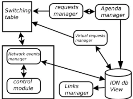
MFO2N consists of several functional elements (see Figure 1)
of which a detailed description is given below.
MFO2N could be used for transmitting several type of
information including data messages. However for simplicity sakes only bandwidth reservation requests are submitted to the DTN architecture while propagating in the network, whereas data messages are routed the usual way along an end-to-end chain of available links and nodes.
1) Agenda Manager: Each network node maintains an agenda, a list of events describing its future behaviour. The agenda manager local to each node is responsible for making
resources (links and nodes) available for data transfers. It peri-odically browses the agenda to trigger events whose start time is the current clock time. Thus, when an event is triggered, the corresponding action is executed. If that action is an “Off” action, then the network manager checks the corresponding link state (the link may be transmitting data) and switches it off if the link is not transmitting data; otherwise it is tagged. The tagging introduced here can serve various purposes. For instance, it can be used to monitor the network traffic crossing the link in order to take more intelligent decisions in case of link’s proactive switch on. However, in our case, it is only used to determine whether the state in which a link is (on or off) was planned or not.
2) Links and Requests Manager: The main goal of the link manager is to achieve pro-active switch-off mechanism monitoring and switching off tagged links, i.e., links pro-actively powered on. An important consideration in the design
of MFO2N is how long should a link, pro-actively powered
on, remain on before it is switched off. Three approaches can be considered.
1) Each tagged link has a minimum lifespan of
min_lifespan seconds (the choice of which depends on the network topology), that is tuned according to the network traffic crossing the link. This approach is however difficult to implement.
2) Easier to implement, the second approach considers an arbitrary lifespan of max_lifespan seconds after which the link is switched off if not in use. The maximum lifespan can be the maximum delay on the Internet. 3) The third approach, called the ACK-based, sits between
the previous two approaches. It is based on a straightfor-ward principle described as follows: when a link is pro-actively switched on, an acknowledgement of the pushed request is created and stored locally on the node. As the request reaches its destination, an acknowledgement is sent back to the sender. The acknowledgement then triggers on each node the destruction of its “local acknowledgement” if any. The link is normally powered down after the local acknowledgement is deleted, but the acknowledgement may not reach the node, in which case the link is powered down after max_lifespan seconds. The minimum lifespan of a link is chosen according to the network topology as follows: given a network of N nodes, let k be the number of links in the longest path without loop between two network nodes. Assuming that the difference between the moment at which a link is powered on and the moment when it can transmit data is t seconds, the minimum lifespan of a link noted min_lif espan in the worst case is given by t ∗ k seconds.
The request manager task consists of transmitting users bandwidth reservation requests to the under-layer communi-cation software. However, it can switch on a link if needed for transmitting users data.
3) Virtual request manager: The DTN retransmission mechanism requires that each message traversing a forwarder
node (router) be stored before retransmission. We leverage that to make a copy of each request stored by ION in its data structure known as an ION database or SDR for Software Data Recorder. The duplicated request known as
“virtual request” is then stored in an MFO2N data structure,
which is for convenience called the application database. As a request leaves the node (is forwarded), its corresponding virtual request is removed from the application database.
The virtual request manager, not mandatory on non-router nodes, periodically browses the application database and switches on one or several links when either it finds a request whose lifespan has expired or the application database size has exceeded a given threshold TH. This process is called “proac-tive switch on” of link and is summarised in Algorithm 1.
Algorithm 1: Proactive Switch On.
Input: TH: threshold, DB: application database, switching table
1 if DB size > TH then
2 for each request req ∈ DB do
3 Switch on its outgoing link l on the basis of the
switching table;
4 Tag l and remove req from DB;
5 end 6 end 7 else
8 if ∃ a request req ∈ BD whose lifespan is elapsed
then
9 Switch on its outgoing link l on the basis of the
switching table;
10 Tag l and remove req from DB;
11 end 12 end
4) Network Events Manager: The events manager is re-sponsible for all communication with the control network and “non standard” communication with the under-layer com-munication software ION. The non-standard comcom-munication mentioned above refers to all accesses from the designed application to ION software’s specific data such as its outgoing queues size, dynamic routing decisions and user data.
5) Control Network/Module: The Magic Packet Technol-ogy was recently introduced to remotely wake up sleeping nodes on a network. Since this is accomplished by sending a specific packet of information, called the Magic Packet to the sleeping node, the communication will fail when the receiver is down. To overcome this problem, it is becoming common to believe that an alternative low power consuming network should be used to access switched-off network components. Called control network in our work, the alternative low-power network can be a GPRS (General Packet Radio Service) network.
B. MFO2N Design Considerations
One of the most important features of MFO2N is its
capability to switch on/off links when needed, but the problem is how to determine which links should be powered on given a specific user request. The routing process usually forwards packets on the basis of the routing table, which maintains a record of the routes to various network destinations. Similarly,
MFO2N makes links available on the basis of a switching table
that maintains a record not of the routes but of the links to various network destinations.
1) Links Selection: The switching table maintained by each routing node reflects the routing process performed by the communication protocol ION. It therefore needs to be updated each time a new communication opportunity appears. To this
end, MFO2N uses previous routing decisions made by ION
to predict which link should be used to various network destinations.
There can be many entries for the same destination, but our implementation always chooses the first. However, a more intelligent design would take the link leading to the less power consuming path.
2) Link Representation: ION uses unidirectional links, thus a bidirectional link connecting a node A to a node B denoted A←→B will be represented by a couple of unidirectional links as follows: A←B, B→A. Each node maintains a record of links of each of the extremities. For instance, considering the following network configuration A←→B←→C, nodes A, B, and C will maintain respectively A{A→B}, B{B→A, B→C}, and C{C→B}. So doing, we ensure that links power on/off are synchronised.
C. Example
This section presents an example scenario for better
un-derstanding of the MFO2N execution model. The most
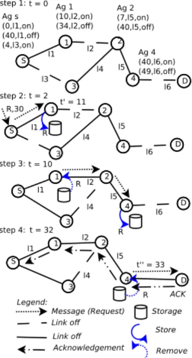
repre-sentative execution steps are depicted in Figure 2. Each node maintains an agenda per outgoing link, but only one agenda is shown here for the sake of clarity.
Initially, i.e, at time t = 0, no path exists between source and destination. At time t = 2s (step 2) the source node S has a message of lifespan 30 seconds destined for the node D. As the link to the next hop i.e, node 1 toward the destination is on, the message is forwarded without any delay to node
1. The message is then stored by node 1 as the link l2 to
the next hop toward the destination is off. A transmission opportunity arises at t = 11 (when a link is switched on, the time after which it is able to send and/or receive data can vary significantly according to many factors including its technology, the distance between its extremities, etc. In our case we assume that a link after being switched on will be available for transmitting or receiving data only after 1s) between node 1 and node 2, the message is then forwarded to
node 2which immediately transmits it to node 4. At this point
node 4does not have any next hop to route the message to the destination D, so the message is stored while waiting either for a communication opportunity or for its lifespan to expire. At time t = 32 (step 4) since the message lifespan is expired,
!"#$ %&'()'*+, %-&'()'*., %-'(/'*+, !"#) %)&'(0'*+, %/-'(0'*., !"#0 %1'(2'*+, %-&'(2'*., !"#-%-&'(3'*+, %-4'(3'*., 5#6#& 5#6#0 7'/& 7 5#6#)& 7 5#6#/0 !"# () (0 (/ (- (2 (3 8 9 ) 0 / -9 9 9 8 8 8 / / / ) ) ) 0 0 0 -7 7 () () () (0 (0 (0 (-(2 (2 (2 (3 (3 $5:;#)< $5:;#0< $5:;#/< $5:;#-< 5=#6#)) 5==#6#// $%&%'() $*'+,-. /%001&%,23%45%067 $*'+,-. !8+'-9:%(&%;%'6 <6-=1&% <6-=% 3%;->%
Figure 2: An example of MFO2N execution scenario.
the proactive switch-on mechanism powers on the link to the next hop which is actually the destination. The message is forwarded to the destination D at time t = 33s. Upon receiving the message, node D then sends an acknowledgement (ACK) to the source node S. On the path to node S the ACK requests all links that were switched on pro-actively to switch off if necessary.
V. EVALUATION
The evaluation of MFO2N was performed on the Grid5000
platform [14]. We deployed via ION a 10-node network topology comprising 6 DTN forwarders (core nodes) and 4 end-nodes all running the 2.2.1 version of the customized ION software. The considered network topology is realistic as it includes heterogeneous links, and exhibits many Internet-like characteristics such as: cross traffic, multiple routing possibili-ties between nodes, and bandwidth sharing. For simplicity and clarity sakes, the bandwidth is reduced by factors of 10 and 20; network nodes numbered from 1 to 10, and links denoted as shown in Figure 3.
During all experiments, max_lif espan and min_lif espan parameters were set to 35 and 10 seconds respectively. Links previously switched on pro-actively were switched off follow-ing the ACK-based approach whereas the maximum number of requests (TH) residing on a forwarder was set to 10.
We consider several agenda scenarios of a few minutes in which end nodes, i.e, nodes 1, 2, 3 and 4, send and/or re-ceive bandwidth reservation requests. A bandwidth reservation request is injected into the network by one of these nodes every 10 seconds; source and destination nodes are chosen randomly. In this way, we are able to repeat the experiment with the same number of requests crossing the network at any moment. However, for simplicity all requests injected in the
!"#$%&' !"#$%&' ()*+, (-*+, (+*., (.*!", (!"*/, (/*0, (0*), (!*/, (1*!", (2*), 2 ) -1 ! + . !" 0 / 3#4#!""#$%&' 3 3 3 3 3 3 3 3
Figure 3: Network topology.
0 1 2 3 4 5 6 7 8 9 10 11 12 13 14 15 16 2 3 4 5 6 7 8 9
Response time in second
Number of requests (a) Response time distribution
0 1 2 3 4 5 6 7 8 9 10 11 0 50 100 150 200 250 300 350 400 450 Number of links Time in second active links
(b) Active links variation Figure 4: Evaluation scenario.
network along with the experiment do not alter the agenda. It is worth to mentioned that a reservation request normally alter the agenda once it is acknowledged.
Due to lack of space, we only present results from one scenario, in which we consider an empty agenda (i.e., an agenda with only one event calling the network to switch off at the beginning of the experiment) along with requests whose lifespan is 5 seconds each.
We instrumented the requests’ acknowledgement messages to derive the response time of bandwidth reservation requests sent during the experiment. Figure 4a presents the distribution of response times for the bandwidth reservation requests. It can be seen from the figure that many requests are acknowledge before the end of their expected response time, which is 5s. However, some requests are acknowledged several seconds af-ter their expected response time, a factor that can be attributed to these requests following a path along which many links had to be switched on (in our scenario, once a link is switching on, it will be able to send or receive messages after 1s). We are investigating whether we can provide bounds for response time.
The variation in the number of active links on the network over time is presented in Figure 4b. The plot shows that despite the network being rarely entirely active, only half of the links
are on average powered on all the time. Figure 4b actually demonstrates the ability of our framework of guaranteeing reasonable response times in a network that is likely to be off to save energy.
VI. CONCLUSION
In this paper, we looked at the possibility of deploying a DTN system over a high performance dedicated wired network infrastructure which, for specific reasons such as saving en-ergy, is designed with the capability of switching equipments off and on. Our main objective was to make the network infras-tructure’s off-periods transparent to users by guaranteeing on demand response times and connectivity during these periods.
To this end, we developed MFO2N, a DTN-based fault tolerant
framework that offers, in addition to the DTN ability to enable communication through intermittently available links, the capability of ensuring specific delivery delays. We then
run MFO2N on a 10-node network topology deployed on
the Grid5000 platform and showed through experiments and examples the feasibility of our approach. One of the major contributions of this paper is the ongoing DTN deployment effort in wired networks which is almost non-existent in the literature due to the lack of feasible scenarios. This work is ongoing, and we envisage to integrate our framework as a module of the under-layer communication software.
ACKNOWLEDGEMENT
This work is supported by the Hemera INRIA Large Wingspan project. The authors would like to acknowledge Anne-Cécile Orgerie (Ecole Normale Superieure of Lyon) for her help in providing trace results as well as the ION software developer’s team.
REFERENCES
[1] V. Cerf et al., Delay-Tolerant Network Architecture, IETF RFC 4838, informational, April 2007.
[2] K. Fall. A delay-tolerant network architecture for challenged internets. In ACM SIGCOMM, 2003.
[3] K. Scott and S. Burleigh, Bundle Protocol Specification, IETF RFC5050, experimental, November 2007.
[4] http://www.dtnrg.org/
[5] JPL D-48259, Interplanetary Overlay Network (Design and Operation), V1.6, 3 October 2008.
[6] Scott Burleigh. Interplanetary overlay network: An implementation of the DTN bundle protocol. In 2007 4th IEEE Consumer Communications and Networking Conference, pages 222-226. IEEE, January 2007.
[7] http://www-valoria.univ-ubs.fr/SARAH/ [8] http://www.haggleproject.org/ [9] http://www.jpl.nasa.gov/
[10] N. Laoutaris, G. Smaragdakis, R. Sundaram, and P. Rodriguez. Delay-Tolerant Bulk Data Transfer on the Internet. In Proceedings of ACM SIGMETRICS 2009, Seattle, WA, June 2009.
[11] N. Laoutaris, P. Rodriguez, Good Things Come to Those Who (Can) Wait or How to Handle Delay Tolerant Traffic and Make Peace on the Internet, in Proc. of ACM HotNets’08.
[12] A. C. Orgerie, L. Lefevre and I. Guerin-Lassous, Energy-Efficient Bandwidth Reservation for Bulk Data Transfers in Dedicated Wired Networks, Journal of SuperComputing, Special issue on Green Networks, March 2011.
[13] F. Warthman, Delay-tolerant networks (DTNs) : A tutorial v1.1, March 2003.
[14] F. Cappello et al, Grid’5000: A large scale, reconfigurable, controlable and monitorable grid platform, in 6th IEEE/ACM International Workshop on Grid Computing, Grid’2005, Seattle, Washington, USA, Nov.2005.