HAL Id: tel-02942992
https://tel.archives-ouvertes.fr/tel-02942992
Submitted on 18 Sep 2020
HAL is a multi-disciplinary open access archive for the deposit and dissemination of sci-entific research documents, whether they are pub-lished or not. The documents may come from teaching and research institutions in France or abroad, or from public or private research centers.
L’archive ouverte pluridisciplinaire HAL, est destinée au dépôt et à la diffusion de documents scientifiques de niveau recherche, publiés ou non, émanant des établissements d’enseignement et de recherche français ou étrangers, des laboratoires publics ou privés.
Insights into the biomass based compounds valorization
in batch versus continuous flow
Deyang Zhao
To cite this version:
Deyang Zhao. Insights into the biomass based compounds valorization in batch versus continuous flow. Chemical and Process Engineering. Université de Technologie de Compiègne, 2020. English. �NNT : 2020COMP2551�. �tel-02942992�
Par Deyang ZHAO
Thèse présentée
pour l’obtention du grade
de Docteur de l’UTC
Insights into the biomass based compounds
valorization in batch versus
continuous flow
Soutenue le 16 juin 2020
Spécialité : Génie des Procédés Industriels et développement
durable : Transformations intégrées de la matière renouvelable
Université de Technologie de Compiègne
Ecole Doctorale : Sciences pour l’ingénieur
Thèse présentée par
Deyang ZHAO
Pour le titre de Docteur en Génie des Procédés Industriels et du
Développement Durable
Insights into the biomass based compounds
valorization in batch versus continuous flow
Thèse dirigée par le Professeur Christophe LEN
Soutenue le 16 Juin 2020 devant le jury composé de :
Mija Alice Professeur Université Nice Sophia Antipolis Rapporteur
Ponchel Anne Professeur Université d’Artois Rapporteur
Pinel Catherine Directeur de Recherche IRCELyon Examinateur
Richel Aurore Professeur Université de Liège Examinateur
Luque Rafael Professeur Universidad de Cordoba Examinateur
Sels Bert Professeur Katholieke Universiteit Leuven Examinateur
Bals Oliviers Maître de Conférences Univ. de Technologie de Compiègne Examinateur Len Christophe Professeur Univ. de Technologie de Compiègne
Acknowledgements
This PhD work was started from 18/10/2016 in the laboratory Transformations Intégrées de la Matière Renouvelable (TIMR, EA4297) of the Université de Technologie de Compiègne (UTC) for 1 year and then in the Institute of Chemistry for Life and Health Sciences of École national supérieure de Chimie de Paris (Chimie ParisTech) for 2 years and a half, the PhD work was under the supervision of Prof. Christophe Len.
First of all, I would like to thank the director of my thesis, Prof. Christophe Len for his scientific help, support and guidance during my PhD. Three and a half years before, Christophe gave me this opportunity of learning abroad. I enjoy my life in France, a developed, democratic state with beautiful environment. Most importantly, the study with Christophe is unforgettable; he is always a humorous, modest, kind-hearted, decent and reliable supervisor. I appreciate his trust for giving me the freedom to design my experiment. The opportunity of an oral presentation in an international conference (ISGC 2018 in La Rochelle, France), the first time attending the international meeting, was unforgettable experience for me.
I also want to thank China Scholarship Council (CSC) for the financial support during my PhD. Without it I can’t finish my PhD studying. It’s also a great honor to me. Thank you so much my motherland. The 70th anniversary is a landmark in the history, as well as a new starting point of a journey towards a more promising future. I wish my motherland all the best in the year ahead.
Universidad de Cordoba (Spain) for giving me the opportunity to work in his group from 01/10/2017 to 30/12/2017. Even only three months, but it was a good chance to learn knowledge about catalyst characterization, flow chemistry and so on, it broadened my horizon. Most importantly, it’s a good platform to communicate with a lot of brilliant researchers in the groups. Rafael is the person I’d want to be. Efficient, energized, confidence and knowledgeable.
I want to express my gratitude to the members of the jury that participate in my PhD defense. I would especially like to acknowledge the referees of my thesis, and besides, I would like thank Prof. Konstantinos from the department of chemistry, Aristotle University of Thessaloniki (Greece) for helping me to analyze the catalysts. I particularly thank Daily and Yantao for guiding me how to perform the experiments when I was confused, the time spending on my manuscript too. We are on good terms. We are great buddies. No needs more words.
I would like to thank my colleagues Frédéric, Sarra, Sophie, Audrey and Denis, they come from the group in Compiègne. Pepijn, Weiyi, Ana, Antonio, and all the colleagues from Rafael’s group, 2017 Christmas holiday, the happy time in Cordoba. Special thanks to Pepijn who helped me a lot to draft the first English manuscript of my life. My Chinese friends: Lu, Rui, Zhi, Congcong et al. The first year, we celebrated Chinese New Year together.
Thanks to supervisor Prof. Virginie Vidal and all colleagues from the group in Paris, good opportunity to study in Chimie ParisTech, I made lots of excellent friends here, especially Bin, we are tight. Longsheng, Amine, Mohamad, Aymane and Sudipta etc…
Of course, I ought to show great gratitude to the selfless love from my parents, Chengrong, Shujun and my sister Mingming. My family was always the exhaustless energy source to me all the time. Another important thing during my PhD is my marriage with Ting in 19/08/2019, the unforgettable moment for me. I love you, my wife, forever. No matter what happen in the future, we can overcome together! You are my sunshine. Thank you for your support and your encouragements, especially when I was homesick. Thank you for trying to understand my work and listening to me when I needed it.
Table of content
Acknowledgements ... 2 Table of content ... 5 List of Tables ... 9 List of Figures ... 10 List of Schemes ... 14 Abbreviations ... 15 General Introduction ... 18Chapter 1. Alcoholysis of furfuryl alcohol to alkyl levulinates using zeolites in continuous flow ... 43
1.1. Abstract 1.2. Introduction 1.3. Experiment section 1.3.1. Materials, solvents and reagents 1.3.2. Catalyst synthesis and characterization 1.3.3. Batch alcoholysis experiments 1.3.4. Continuous flow alcoholysis experiments 1.3.5. Product analysis 1.4. Results and discussion 1.4.1. Catalyst screening 1.4.2. Effect of reaction pressure for the production of ML 1.4.3. Effect of FA concentration with flow rate for the production of ML 1.4.4. Effect of reaction temperature for the production of ML 1.4.5. Stability of the catalyst and recycling 1.4.6. Effect of the alcohol chain length for the production of AL 1.4.7. Plausible mechanism 1.5. Conclusion 1.6. References Chapter 2. Conversion of alkyl levulinates into γ-valerolactone in the presence of Ru/C in continuous flow ... 74
2.1. Abstract 2.2. Introduction 2.3. Experiment section
2.3.1. Materials, solvents and reagents 2.3.2. Continuous flow experiments 2.3.3. Product analysis
2.4. Results and discussion
2.4.1. Catalyst screening
2.4.2. Effect of reaction temperature for the production of GVL 2.4.3. Effect of reaction pressure for the production of GVL 2.4.4. Effect of flow rate for the production of GVL
2.4.5. Effect of ML concentration for the production of GVL
2.4.6. Effect of the nature of the alkyl levulinate (AL) for the production of GVL 2.4.7. Stability of the catalyst and recycling
2.5. Conclusion 2.6. References
Chapter 3. Insights into the selective oxidation of hydroxymethylfurfural to 5-hydroxymethyl-2-furancarboxylic acid using silver oxide ... 98
3.1. Abstract 3.2. Introduction 3.3. Experiment section
3.3.1. Materials, solvents and reagents 3.3.2. Catalyst characterization 3.3.3. Catalytic experiments 3.3.4. Products analysis
3.4. Results and discussion
3.4.1. Catalyst and base screening
3.4.2. Effect of base amount for the production of HMFCA 3.4.3. Effect of catalyst amount for the production of HMFCA
3.4.4. Effect of reaction temperature and reaction time for the production of HMFCA 3.4.5. Effect of aq. H2O2 amount for the production of HMFCA
3.4.6. Effect of microwave and continuous flow for the production of HMFCA 3.4.7. Stability of the catalyst and recycling
3.4.8. XRD analysis 3.4.9. XPS analysis 3.4.10. SEM-mapping analysis 3.4.11. TEM analysis 3.4.12. Plausible mechanism 3.4.13. Catalyst regeneration 3.4.14. Production purification 3.5. Conclusion 3.6. References
Chapter 4. Insights into the microwave-assisted oxidation of hydroxymethyl furfural to added-value compounds over ruthenium based catalysts in batch and continuous flow reactors ... 132
4.2. Introduction 4.3. Experiment section
4.3.1. Materials, solvents and reagents 4.3.2. Catalyst synthesis and characterization 4.3.3. Catalytic experiments
4.3.4. Products analysis
4.4. Results and discussion
4.4.1. MW batch for the production of FDCA 4.4.1.1. Catalyst screening
4.4.1.2. Effect of base for the first step production of FFCA 4.4.1.3. Effect of base amount for the first step production of FFCA 4.4.1.4. Effect of oxidizing agent for the first step production of FFCA 4.4.1.5. Effect of catalyst amount for the first step production of FFCA 4.4.1.6. Effect of reaction time for the second step production of FDCA 4.4.1.7. Effect of base amount for the second step production of FDCA 4.4.2. Air flow under conventional heating for the production of FDCA 4.4.3. MW continuous flow for the production of FDCA
4.4.4. Stability of the catalyst and recycling 4.4.5. N2 adsorption analysis
4.4.6. XRD analysis 4.4.7. ICP-OES analysis
4.5. Conclusion 4.6. References
Chapter 5. One-pot FDCA diester synthesis from mucic acid and their solvent-free regioselective polytransesterification for production of glycerol-based furanic polyesters ... 171
5.1. Abstract 5.2. Introduction 5.3. Experiment section
5.3.1. Materials, solvents and reagents 5.3.2. Detecting instruments
5.3.3. Products synthesis, analysis and characterization 5.3.3.1. Diethyl furan-2,5-dicarboxylate (DEFDC)
5.3.3.2. Bis(hydroxyethyl)-2,5-furandicarboxylate (BHEFDC) 5.3.3.3. Bis(2,3-dihydropropyl)-2,5-furandicarboxylate (BDHPFDC) 5.3.3.4. General Melt Polytransesterification
5.4. Results and Discussion
5.4.1. Effect of catalyst variety and catalyst amount for the production of FDCA 5.4.2. Effect of reaction temperature for the production of FDCA
5.4.3. Effect of reaction time for the production of FDCA 5.4.4. Optimization of DEFDC
5.4.5. Optimization of BHEFDC 5.4.6. Optimization of BDHPFDC 5.4.7. Optimization of PEF 5.4.8. Optimization of PHPF 5.4.9. Optimization of PDGF 5.4.10. FT-IR analysis 5.4.11. DSC analysis 5.4.12. TGA analysis
5.4.13. XRD and SEM analysis 5.4.14. EDX analysis
5.5. Conclusion 5.6. References
General Conclusions ... 199 Supporting information ... 204
Chapter S1. Continuous flow alcoholysis of furfuryl alcohol to alkyl levulinates using zeolites
Chapter S2. Conversion of alkyl levulinates into γ-valerolactone in the presence of Ru/C in continuous flow
Chapter S4. Insights into the microwave-assisted oxidation of hydroxymethyl furfural to added-value compounds over ruthenium based catalysts in batch and continuous flow reactors
Chapter S5. One-pot FDCA diester synthesis from mucic acid and their solvent-free regioselective polytransesterification for production of glycerol-based furanic polyesters
List of Tables
Table 0.1 Commonly used organic solvents classified according to their heating efficiency (tan δ) in the microwave field
Table 0.2 Fundamental information of furfural
Table 0.3 Fundamental information of 5-hydroxymethylfurfural Table 1.1 Acid catalysts reported for the conversion of FA to AL
Table 1.2 Total specific surface area (SSA), average pore size (APS), total pore volume (TPV) and meso/macro pore & external area/ volume of HZSM-5 and H-Y zeolites
Table 1.3 Si/Al ratio and acidic properties of H-ZSM-5 and H-Y zeolites
Table 1.4 Effect of alcohol chain length in continuous flow alcoholysis at 170 °C and 50 bar using 1.6 M FA at 0.2 mL min-1 feed rate and 200 mg H-ZSM-5-50
Table 2.1 5%Ru/C as catalysts reported for the conversion of LA and AL to GVL Table 2.2 Effect of AL molecular weight as starting material for the production of GVL Table 3.1 Conversion of HMF into HMFCA under different catalysts and bases
Table 3.2 Conversion of HMF into HMFCA under different temperatures
Table 3.3 Comparison between conventional heating, microwave irradiation and continuous flow in the oxidation of HMF to HMFCA
Table 3.4 pH change in pristine and spent Ag2O during different time
Table 4.1 Activated carbon support Ru catalysts for the conversion of 5-hydroxymethyfurfural (HMF) to 2, 5-furandicarboxylic acid (FDCA)
Table 4.2 Optimization of HMF oxidation to FFCA using 5% Ru/C catalyst Table 4.3 Microwave-assisted continuous HMF oxidation to FDCA
Table 4.4 Catalyst reusability studies and acid-base properties of fresh and spent catalyst Table 4.5 Porosity and crystal size data of the fresh and spent catalysts
Table 4.6 ICP-OES measurement of Ru leaching under different reaction process
Table 5.1 Dehydration of mucid acid in the presence of acid catalyst for the production of FDCA
Table 5.2 Dehydration of mucid acid in different temperature for the production of FDCA Table 5.3 Dehydration of mucid acid in different reaction time for the production of FDCA Table 5.4 Production of DEFDC starting from mucic acid in a one-pot two steps reaction
List of Figures
Fig. 0.1 Major conversion technologies for converting biomass into useful energy carriers. Fig. 0.2 Electric (E) and magnetic (H) field components in microwaves.
Fig. 0.3 The difference between microwave and conventional heating nature. Fig. 0.4 The frequency and wavelength of microwave radiation region.
Fig. 0.5 The fundamental mechanism of microwave heating: (A) dipole rotation; (B) ionic migration.
Fig. 0.6 Two of the small scale dedicated microwave units for scientific applications. Fig. 0.7 Reactors used for continuous flow synthesis.
Fig. 0.8 Comparison of batch microwave and flow processing (conductive heating). Fig. 0.9 Different type of laboratory scale continuous flow reactors.
Fig. 0.10 Synthesis and application of two platform molecules: Furfural and 5-Hydroxymethylfurfural.
Fig. 1.1 Methyl levulinate (ML), α-angelica lactone (AAL), β-angelica lactone (BAL) and 2-methoxy-2-methylfuran (MMF) yields obtained after 5 min batch alcoholysis of 0.2 M furfuryl alcohol (FA) assisted by microwave irradiation in methanol (MeOH) at 150 °C using 50 mg of zeolite catalyst.
Fig. 1.2 Effect of hydrodynamic pressurization on ML and BAL yields over 2 h on stream in continuous flow alcoholysis at 170 °C using 200 mg H-ZSM-5-50 and 0.2 M FA in MeOH at 0.2 mL min-1 feed rate.
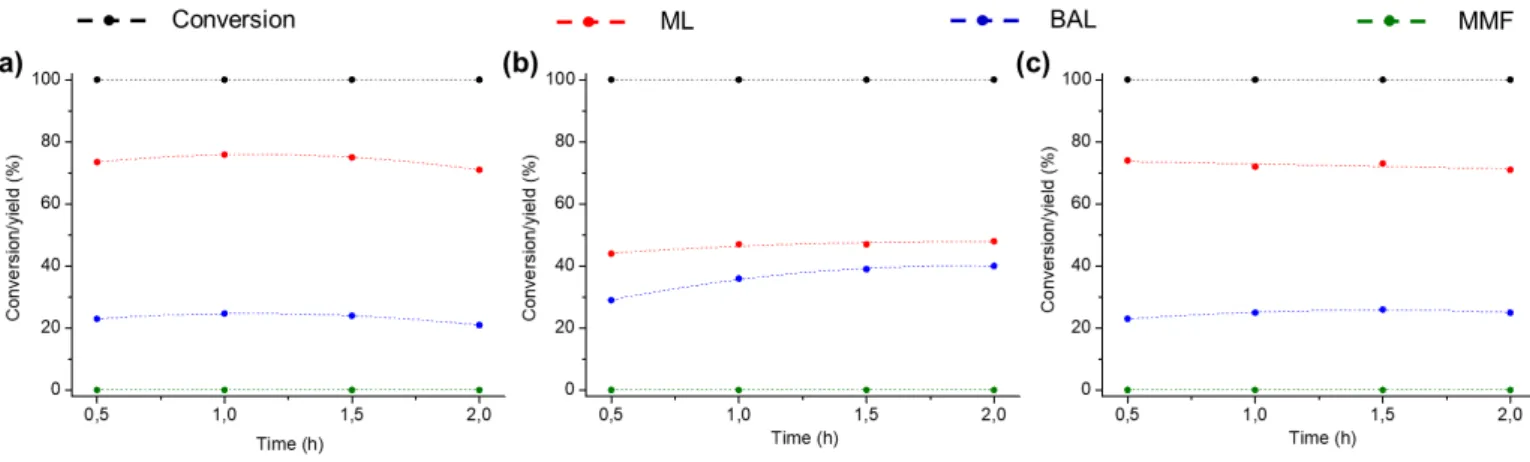
Fig. 1.3 Effect of FA load in MeOH and flow rate on (a) conversion and (b) yield of ML, (c) BAL and (d) MMF, observed in continuous flow alcoholysis at 170 °C and 50 bar using 200 mg H-ZSM-5-50.
Fig. 1.4 Evolution the ML yield with the weight hourly space velocity (WHSV, g g-1h-1)
at different flow rates, as observed in continuous flow alcoholysis at 170 °C and 50 bar using 200 mg H-ZSM-5-50.
Fig. 1.5 Effect of reaction temperature on conversion and product yields in continuous flow alcoholysis using 200 mg H-ZSM-5-50 and 1.6 M FA in MeOH at 0.2 mL min-1 feed rate.
Fig. 1.6 Operational stability in continuous flow alcoholysis experiments at at 170 °C and 50 bar using 200 mg H-ZSM-5-50 and (a) 1.6 M FA and (b) 0.2 M FA, both in MeOH at 0.2 mL min-1 feed rate.
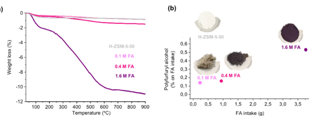
Fig. 1.7 Weight loss observed during thermogravimetric (TGA) analysis from fresh and used H-ZSM-5-50 recovered after continuous flow alcoholysis (170 °C, 50 bar, 0.2 mL min-1) using different feed loads of FA in MeOH.
Fig. 1.8 Comparison of catalytic activity in continuous flow alcoholysis of 0.2 M FA in MeOH (170 °C, 50 bar, 0.2 mL min-1), using 200 mg of (a) fresh H-ZSM-5-50.
(b) spent H-ZSM-5-50 recovered after 800 °C for 9 h. (c) spent H-ZSM-5-50 recovered after 500 °C for 4 h.
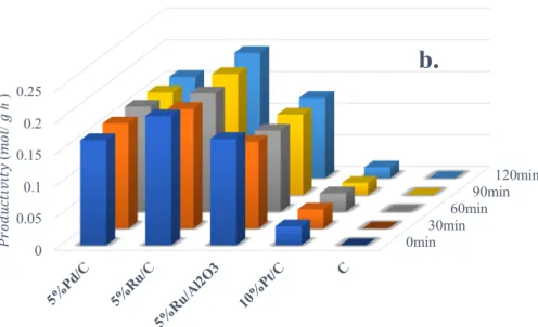
Fig. 1.9 Plausible FA alcoholysis reaction mechanism in HZSM-5-50 catalytic system. Fig. 2.1 Effect of catalysts and residence time on (a) the GVL yields and (b) on the
productivity. Reaction conditions: ML (0.2 M), catalyst (0.88 cm3 of the CatCart
cartridge), 2-PrOH, 130 °C, 20 bar, 0.4 mL min-1.
Fig. 2.2 Effect of reaction temperature on GVL productivity and products yield in continuous flow process. Reaction conditions: ML (0.2 M), 5% Ru/C (330 mg),
2-PrOH, 100-150 °C, 20 bar, 0.4 mL min-1.
Fig. 2.3 Effect of hydrodynamic pressure on GVL productivity and products yield and productivity in continuous flow process. Reaction conditions: ML (0.2 M), 5% Ru/C (330 mg), 2-PrOH, 150 °C, 20-60 bar, 0.4 mL min-1.
Fig. 2.4 Effect of flow rate on GVL productivity and products yield in continuous flow process. Reaction conditions: ML (0.2 M), 5% Ru/C (330 mg), 2-PrOH, 150 °C, 40 bar, 0.2-0.8 mL min-1.
Fig. 2.5 Effect of flow rate and substrate concentration with a constant ML feeding rate on GVL and MHP yields in continuous flow process. Reaction conditions: ML (0.2-0.8 M), 5% Ru/C (330 mg), 2-PrOH, 150 °C, 40 bar, 0.2-0.8 mL min-1.
Fig. 2.6 Operational stability of the catalyst 5% Ru/C in continuous flow alcoholysis of ML. Reaction conditions: ML (0.4 M), 5% Ru/C (330 mg), 2-PrOH, 150 °C, 40 bar, 0.8 mL min-1.
Fig. 3.1 Effect of Na2CO3 amount on HMFCA synthesis. Reaction condition: HMF (37.8
mg), Na2CO3 (0-158 mg) Ag2O (20 mg), 10 mL HPLC water, oil bath 90 ºC under
stirring 300 rpm, 8.1 wt% H2O2 aqueous with flow rate 0.2 mL min-1 during 1 h.
Fig. 3.2 Effect of catalyst amount on HMFCA synthesis. Reaction condition: HMF (37.8 mg), Na2CO3 (126.4 mg), Ag2O (0-25 mg), 10 mL HPLC water, oil bath 90 ºC
under stirring 300 rpm, 8.1 wt% H2O2 aqueous with flow rate 0.2 mL min-1 during
1 h.
Fig. 3.3 Effects of temperature and reaction time on HMFCA synthesis. Reaction condition: HMF (37.8 mg), Na2CO3 (126 mg), Ag2O (20 mg), 10 mL HPLC
water, oil bath 90 or 120 ºC under stirring 300 rpm, 8.1 wt% H2O2 aqueous with
flow rate 0.1-2 mL min-1 during 6-120 min.
Fig. 3.4 Effects of H2O2 concentration on HMFCA synthesis. Reaction condition: HMF
(37.8 mg), Na2CO3 (126 mg), Ag2O (20 mg), 10 mL HPLC water, oil bath 90 ºC
under stirring 300 rpm, 0-10.6 wt% H2O2 aqueous with flow rate 0.2 mL min-1
Fig. 3.5 Stability test of Ag2O. Reaction condition: HMF (37.8 mg), Na2CO3 (126 mg),
Ag2O (20 mg), 10 mL HPLC water, oil bath 90 ºC under 300 rpm stirring, 8.1
wt% H2O2 aqueous with flow rate 0.2 mL min-1 during 60 min. HMF, Na2CO3
and H2O2 aqueous were adjusted to recovered catalyst.
Fig. 3.6 XRD patterns of the fresh and spent catalyst, after batch and continuous flow reaction.
Fig. 3.7 Deconvoluted XPS spectra of the fresh catalyst (A-C) and the spent catalyst after the batch (D-F) and the continuous flow reaction (G-I).
Fig. 3.8 SEM-mapping micrographs of the fresh catalyst (A-D) and the spent catalyst after the batch (E-H) and the continuous flow reaction (J-M).
Fig. 3.9 TEM micrographs of the fresh catalyst (A) and the spent catalyst (B) and the continuous flow reaction (C). Insets: size distribution histograms based on TEM images (100 nanoparticles).
Fig. 3.10 Plausible HMF oxidation mechanism in Ag
2O-H2O2 catalytic system.
Fig. 4.1 Catalyst screening experiments. Reaction conditions: HMF (37.8 mg, 0.3 mmol), Na2CO3 (31 mg, 0.3 mmol), catalysts (25 mg) in water (5 mL), 2 min under MW
(30 W) and then addition of aqueous H2O2 (6.5 wt %) with a flow rate of 1 mL
min-1 during 10 min under MW (8 W).
Fig. 4.2 HMF conversion, FFCA, DFF and FDCA yields versus reaction time. Reaction conditions: HMF (37.8 mg, 0.3 mmol), Na2CO3 (31 mg, 0.3 mmol), catalysts (25
mg) in water (5 mL), 2 min under MW (30 W) and then addition of aqueous H2O2
(6.5 wt %) with a flow rate of 0.1-10 mL min-1 during 1-60 min under MW (8
W).
Fig. 4.3 Optimization of HMF oxidation to FDCA via FFCA under microwave-batch conditions.
Fig. 4.4 HMF conversion and FFCA, DFF, FDCA yield at different reaction times. Reaction conditions: HMF (37.8 mg, 0.3 mmol), Na2CO3 (31 mg, 0.3 mmol),
catalysts (25 mg), air flow (3 mL min-1) in water (15 mL), 80 °C.
Fig. 4.5 Optimization of HMF oxidation to FDCA via FFCA with air flow. Reaction conditions: HMF (37.8 mg, 0.3 mmol), Na2CO3 (31 mg, 0.3 mmol), catalysts (25
mg), air flow (3 mL min-1) in water (15 mL), 80 °C, 6 h and then addition of
NaOH (95.9 mg, 2.4 mmol) in the presence of air flow (3 mL min-1), 80 °C, 2-20
h.
Fig. 4.6 N2 adsorption-desorption isotherms of fresh and spent catalysts.
Fig. 4.7 X-ray diffractograms of the fresh and spent samples. Fig. 5.1 (a) 13C-NMR spectrum of PEF in DMSO-d
6; (b,d) 13C- and 1H-NMR spectra of
Fig. 5.2 DSC thermograms of (a) PEF and (b) PHPF (c) PDGF after quenching their melted solution with liquid N2. Heating and cooling rate was 10 °C/min.
Fig. 5.3 TGA traces curves of PEF and PHPF.
Fig. 5.4 XRD diffractograms and SEM images of synthesized (a) PEF and (b) PHPF. Fig. 5.5 EDX spectra of (a) PEF and (b) PHPF.
Fig. S1.1 Illustration of the ThalesNanoTM Phoenix equipment used for continuous flow
alcoholysis of furfuryl alcohol feedstocks in methanol, ethanol or n-propanol. Fig. S1.2 XRD spectra of (a) pristine H-ZSM-5-50, (b) H-ZSM-5-50 used in continuous
flow acloholysis (1.6 M FA in MeOH, 170 °C, 50 bar, 0.2 mL min-1) and (c) used
H-ZSM-5-50 and regenerated by calcination at 500 °C during 4 h.
Fig. S2.1 Illustration of the ThalesNanoTM H-Cube Pro™ equipment used for continuous flow of methyl levulinate feedstocks in 2-propanol.
Fig. S2.2 NMR of the GVL and methyl 4-hydroxypentanoate(MHP).
Fig. S4.1 Illustration of the MiniFlow 200SS microwave equipment used for microwave batch of HMF oxidation to FDCA.
Fig. S4.2 Illustration of the MiniFlow 200SS microwave equipment used for continuous flow of HMF oxidation to FDCA.
Fig. S5.1 2D-NMR sequences of BDHPFDC: COSY (1H-1H) and HMBC (1H-13C).
Fig. S5.2 1H NMR of PEF in DMSO-d
6 after complete polymerization.
Fig. S5.3 1H NMR of PDGF after polymerization.
Fig. S5.4 Cosy (1H-1H) spectrum of PDGF.
Fig. S5.5 FT-IR spectra of (a) PEF, (b) PHPF and (c) PDGF. Fig. S5.6 TG-DTG curves of (a) PEF and (b) PHPF.
List of Schemes
Scheme 1.1 Production of biomass derived alkyl levulinate via (a) esterification of levulinate acid, (b) alcoholysis of 5-hydroxymethylfurfural alcohol (in green) and (c) alcoholysis of furfural alcohol (in blue).
Scheme 2.1 Production of biomass-derived GVL from cellulose (in green) and hemicellulose (in blue) via AL as a common intermediate.
Scheme 3.1 HMF and its value-added derivatives.
Scheme 4.1 Different pathways for the production of FDCA starting from LCB. Scheme 4.2 Batch microwave-assisted oxidation of HMF to FFCA.
Scheme 4.3 Microwave-assisted oxidation of HMF to FDCA via FFCA in batch reactor. Scheme 5.1 Different ways for the production of 2,5-furandicarboxylic acid starting from
lignocellulose.
Scheme 5.2 Entire synthetic routes to linear furanic polyesters from mucic acid.
Scheme 5.3 Synthesis of BHEFDC starting from DEFDC in the presence of Co(Ac)2 under
microwave radiation.
Scheme 5.4 Synthesis of BDHPFDC starting from DEFDC in the presence of Co(Ac)2 under
microwave radiation.
Scheme 5.5 Synthesis of PEF in the presence of Co(Ac)2.
Abbreviations
AL Alkyl levulinates
AAL α-Angelica lactone
BAL β-Angelica lactone
BDHPFDC Bis(2,3-dihydropropyl)-2,5-furandicarboxylate
BHEFDC Bis(hydroxyethyl)-2,5-furandicarboxylate
BHP Butanol 4-hydroxypentanoate
BHMF 2,5-Bis (hydroxymethyl)furan
BL Butanol levuliante
CSA Camphorsulfonic acid
CTH Catalytic transfer hydrogenation
DEFDC Diethyl furan-2,5-dicarboxylate
DFF 2,5-Diformylfuran
DHMF 2,5-Dihydroxymethyl furan
DHMTHF 2,5-Dihydroxymethyl tetrahydrofuran
DMF 2,5-Dimethylfuran
ECN Effective Carbon Number
EG Ethylene glycol
EHP Ethyl 4-hydroxypentanoate
EL Ethyl levulinate
FDCA 2,5-Furandicarboxylic acid
FDCC Furan-2,5-dicarboxylic acid dichloride
FF Furfural
FFCA 5-Formyl-2-furancarboxylic acid
GBL γ-Butyrolactone
GVL γ-Valerolactone
HMF 5-Hydroxymethylfurfural
HMFCA 5-Hydroxymethylfuroic acid
HMTHF Hydroxymethyl tetrahydrofurfural IL Ionic liquid LA Levulinic acid LCB Lignocellulosic biomass MF 2-Methylfuran MHP Methyl 4-hydroxypentanoate ML Methyl levulinate MMF 2-Methoxy-2-methylfuran
MSA Methanesulfonic acid
MTHF 2-Methyltetrahydrofurane
MW Microwave
PDGF Polydiglycerol-2,5-furandicarboxylate
PEF Polyethylene 2,5-furandicarboxylate
PHPF Polyhydropropyl-2,5-furan dicarboxylate
Pr Productivity
PTA p-Terephthalic acid
PTSA para-Toluenesulfonic acid
RF Response factors
RON Research octane number
TFA Trifluoacetic acid
THF Tetrahydrofuran
THFA Tetrahydrofurfuryl alcohol
General Introduction
Fossil fuels such as coal, oil, and natural gas provided more than three quarters of the world’s energy. The consumption of fossil fuel resources has surged during the 20th century, partially because of the rise of automobile industry. Unfortunately, the growing demand for fossil fuel resources comes at a time of diminishing reserves of these non-renewable resources, such that the worldwide reserves of oil are sufficient to supply energy and chemicals for only about another 40 years [1]. The strong fluctuations (variation, instability) of fossil fuel prices and the increase of greenhouse gas emissions [2] require the discovery of alternative and renewable resources to release the burden of fossil fuels and chemicals.
The renewable energy sources such as solar, wind, hydroelectric, biomass and geothermal power. The nuclear powered sources are fission and fusion. Among them, biomass provides a clean, renewable energy source that could dramatically improve our environment, economy and energy security. Production of energy from biomass also has the potential to generate lower greenhouse gas emissions when compared to the combustion of fossil fuels, because the CO2 released during energy conversion is
consumed during subsequent biomass regrowth. Furthermore, it can reduce the amount of waste sent to landfills and decrease our reliance on fossil resources. Biomass energy also creates thousands of jobs and helps revitalize rural communities. The advantages above have made it the best candidate to replace fossil resources.
Biomass is a general term for material derived from growing plants: including wood and wood wastes, agricultural crops and their waste byproducts, municipal solid
waste, animal wastes, waste from food processing and aquatic plants and algae. It has been used to meet a variety of energy needs, including generating electricity, heating homes, fueling vehicles and providing process heat for industrial facilities. The U.S. Department of Energy in collaboration with the U.S. Department of Agriculture have indicated that there will be an increase in the commodities of chemicals and bio-materials to 25% in 2030 [3].
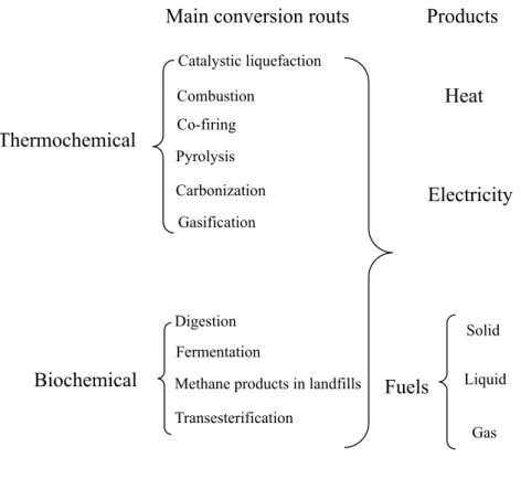
Bioenergy conversion technologies are used to convert biomass into useful energy. These technologies are mainly divided into two categories: thermochemical and biochemical conversion. In thermochemical conversion pathways, heat and chemical catalysts are used for the production of energy from biomass, while biochemical conversion pathways use biological organisms and biological catalysts for transforming biomass into energy and value-added products. A wide range of useful energy products can be obtained from biomass using these conversion technologies. The main conversion technologies, which have been used or are under development for the production of secondary energy carriers is illustrated in Fig. 0.1.
Fig. 0.1. Major conversion technologies for converting biomass into useful energy carriers.
Heating method plays an important role in biomass valorization process. Conventional thermal heating is known as a traditional heating system (with an external heat source such as an oil bath or heating mantle) where heat is transferred from the surface towards the center of the material by conduction, convection, and radiation. This heating system is relatively slow and inefficient and depends on the thermal conductivity of the material and convection currents.
Thermochemical
Biochemical
Main conversion routs Products
Catalystic liquefaction Combustion Co-firing Pyrolysis Carbonization Gasification Digestion Fermentation
Methane products in landfills Transesterification Heat Electricity Fuels Solid Liquid Gas
Fig. 0.2. Electric (E) and magnetic (H) field components in microwaves.
Microwaves are generally defined as non-ionizing radiations, namely electromagnetic waves that are comprised of two perpendicular components (i.e., electric and magnetic fields) as shown in Fig. 0.2 [4]. Microwave heating is different with conventional heating since it can be transmitted, reflected or absorbed toward the reagent. The microwaves can penetrate materials and deposit energy, thus the heat can be produced throughout the volume of the materials rather than an external source (in core volumetric heating). The difference in mechanism for conventional and microwave heating systems was illustrated in Fig. 0.3, the center of the material is at a higher temperature than the surrounding material in microwave heating [5,6]. According to the literature, there are three possible ways (combination of two or all three contributions) of chemical reaction enhancement using microwave irradiation technique [7], including (i) thermal effects (the influence of a high reaction temperature which can be rapidly attained when irradiating polar materials in a microwave field) [8], (ii) specific microwave effects (can be caused by the unique nature of the microwave irradiation heating mechanism in a microwave field and cannot be achieved by conventional heating) [9], and (iii) non-thermal effects (chemical transformation
accelerations that cannot be defined in terms of thermal or specific microwave effects) [10].
Fig. 0.3. The difference between microwave and conventional heating nature.
An intuitive view of microwave was showed in Fig. 0.4. The microwave region of the electromagnetic spectrum is broadly defined as that with wavelengths ranging from 0.01 to 1 m. This corresponds to frequencies of between 0.3 and 300 GHz. Since applications such as wireless devices (2.4 to 5.0 GHz; U.S.), satellite radio (2.3 GHz), and air traffic control operate in this range, regulatory agencies allow equipment for industrial, scientific, and medical (ISM) use to operate at only five specific frequencies: 25.125, 5.80, 2.45, 0.915, and 0.4339 GHz. Domestic microwave ovens operate at 2.45 GHz (corresponding to a 12.25 cm wavelength), and this same frequency has also been widely adopted by companies manufacturing scientific microwave apparatus for use in
Microwave heating
Conventional heating b.
preparative chemistry, with only a few exceptions [11,12].
Fig. 0.4. The frequency and wavelength of microwave radiation region.
Microwave energy was originally applied for heating food. Until the mid-1980s, Gedye et al. first reported the use of microwave heating to accelerate chemical synthesis [13]. Since then, microwave technologies and equipment have been significantly developed, and the number of publications related to microwave-assisted organic synthesis increased dramatically (up to ≈ 5000). In 1998, Grant and Halstead [14] provided a thorough explanation of the underlying theory of the microwave dielectric heating. The microwave heating involves two main mechanisms: dipolar polarization and ionic conduction as sketched in Fig. 0.5 which adapted from Bilecka and Niederberger [15].
In case of dipolar polarization, to absorb microwaves irradiations, a substance structure must be partly negatively and partly positively charged. The dipolar polarization mechanism could be vividly exemplified when water is used. Under the
microwave heating, water molecules try to orientate with the rapidly changing alternating electric field; thus heat is generated by the rotation, friction, and collision of molecules.
As for ionic migration, dissolved charged particles oscillate back and forth under microwave irradiation, and they also collide with neighboring molecules, thereby generating heat. As an example: if equal amounts of distilled water and tap water are heated by microwave irradiation, more rapid heating will occur for the tap water because of its ionic content in addition to the dipolar rotation of water molecules.
Fig. 0.5. The fundamental mechanism of microwave heating: (A) dipole rotation; (B) ionic migration.
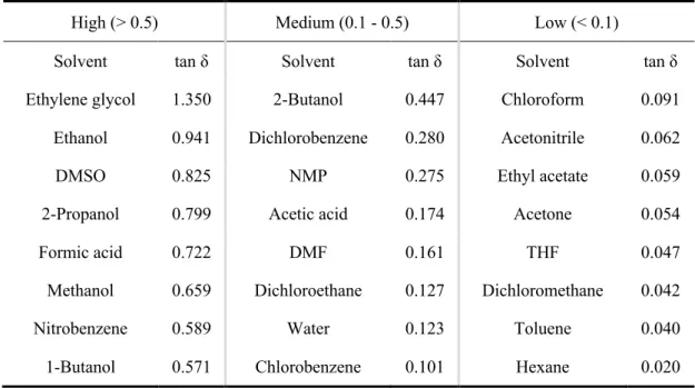
Under microwave irradiation conditions, the ability of a specific substance to convert electromagnetic energy into heat is determined by the so-called loss tangent, tan δ. The high tan δ, the high microwaves absorbing ability a material has. The
definition of the loss factor tan δ is: tan δ = ε’’/ε. Where the dielectric constant (ε), describing the ability of molecules to be polarized by the electric field, and the dielectric loss (ε’’), indicating the efficiency with which electromagnetic radiation is converted into heat. Commonly used organic solvents with high (tan δ > 0.5), medium (tan δ 0.1-0.5), and low microwave absorbing (tan δ < 0.1) are summarized in Table 0.1.
Table 0.1. Commonly used organic solvents classified according to their heating efficiency (tan δ) in the microwave
High (> 0.5) Medium (0.1 - 0.5) Low (< 0.1)
Solvent tan δ Solvent tan δ Solvent tan δ
Ethylene glycol 1.350 2-Butanol 0.447 Chloroform 0.091
Ethanol 0.941 Dichlorobenzene 0.280 Acetonitrile 0.062
DMSO 0.825 NMP 0.275 Ethyl acetate 0.059
2-Propanol 0.799 Acetic acid 0.174 Acetone 0.054
Formic acid 0.722 DMF 0.161 THF 0.047
Methanol 0.659 Dichloroethane 0.127 Dichloromethane 0.042
Nitrobenzene 0.589 Water 0.123 Toluene 0.040
1-Butanol 0.571 Chlorobenzene 0.101 Hexane 0.020
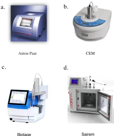
The first purpose built, mono-mode microwave reactor was introduced in the early 1990s by Prolabo, a French company. Today, the main manufacturers of small scale, scientific microwave apparatus are Anton Paar (Monowave), CEM (Discover), Biotage (Initator) and Sairem (Minilabotron 2000). Which are shown in Fig. 0.6.
Anton Paar (Monowave) are capable of heating reactions, in sealed-vessel format, the maximum temperatures can reach to 300 °C. Pressure limits of the glass reaction
vessels used are 300 psi (~20 bar) for the Initator and Discover units and 435 psi (30 bar) for the Monowave (Fig. 0.6 a).
The CEM Discover (Fig. 0.6 b) can be used accommodating round bottom flasks of up to 125 mL capacity. The equipment utilizes 300 W (Discover), 400 W (Initiator), and 850 W (Monowave) magnetrons. The waveguide design and intellectual property of the units are quite different, though all are very effective at heating reactions. Temperature is generally monitored via an infrared detector located below or alongside the reaction vessel. Alternatively, a fiber-optic probe can be immersed in the reaction vessel by means of a thermowell. Pressure measurement is generally by means of a load cell.
Biotage® Initiator (Fig. 0.6 c) represents the latest in microwave synthesis performance. This instrument’s high-end specifications enable the chemist to explore new areas and perform the latest of innovations in chemistry. A reliable and upgradeable platform that allows chemists to make great discoveries in less time.
Fig. 0.6. Four small scale dedicated microwave units for scientific applications.
The Sairem (Minilabotron 2000) (Fig. 0.6 d) is an easy-to-use microwave-assisted reactor, engineered as a system specifically designed to meet all laboratory requirements, the system can be easily configured to perform different applications including reactions in liquid phase, solid phase and gas phase in homogeneous and heterogeneous mixtures. The Minilabotron 2000 is constructed of high-grade stainless steel, with high degree of finishing, i.e. inside and outside surfaces are covered by a non-corrosive, high impact resistant resin layer. The double jacket of the oven allows the operation of the reactor at very high temperature whilst the outside of the oven remains at room temperature.
Anton Paar CEM
a.
b.
c.
Biotage Sairem
Despite the many advantages of microwave-assisted performed in dedicated batch type reactors, one severe limitation is the difficulty in scaling this technology to a production scale level. While in the past few years impressive progress has been achieved in translating small scale microwave chemistry from the milligram or gram scale to a larger batch format providing up to muti-kilogram product quantities, true production scale volumes are beyond the reach of batch microwave reactors mainly because of the restricted penetration depth of microwaves into absorbing materials, that is, solvents or reaction mixtures [16]. In addition, when moving to larger and larger batch reactors many of the genuine benefits of small scale microwave chemistry are in fact lost. In particular, the rapid heating and cooling profiles obtained on a small scale in high-power-density microwave reactors can often not be duplicated on a larger scale, leading to extended processing times.
As a consequence of these apparent limitations in scalability, recent efforts have focused on translating microwave batch reactions to a high temperature continuous flow format (“microwave to flow” paradigm). The main advantage of continuous flow processing is the ease with which reactions can be scaled (without the need for re-optimization) through the operation of multiple systems in parallel (numbering up, scaling out) or related strategies, thereby readily achieving production scale quantities [17].
In flow chemistry, a chemical reaction is run in a continuously flowing stream (Fig. 0.7). It is a well-established technique for using at a large scale when manufacturing large quantities of a given material. Indeed, the short residence times associated with
this type of reactors could avoid long contact between reactants and products and thus increase desired products selectivity. The typically short reaction times (in the order of a few minutes or even seconds) experienced in high-temperature microwave chemistry protocols form an ideal basis for continuous flow processing, in which short residence times within the flow device are essential to achieve efficient throughput. Most importantly perhaps, using standard micro or meso-fluidic reactor (Fig. 0.7 a and b) type flow instrumentation with coils, chips or capillary dimensions <1 mm, heat transfer to and from the reaction mixture is very fast owing to the high surface to volume ratio in these systems. This ensures very rapid heating and cooling rates and therefore eliminates the rationale to apply microwave heating, significantly simplifying the design and construction of flow reactors.
Fig. 0.7. Reactors used for continuous flow synthesis.
Microfluidic chip Catridges Reactor coils a. b. c.
For most of the continuous flow synthetic organic chemistry, the commercially available, high-temperature and pressure capillary (coil) reactors made out of stainless steel have been employed (Fig. 0.7 c). Due to its strength, durability, and corrosion resistance (except against strong acids), stainless steel is the most widely used and easily available metallic alloy. The inner diameters of the capillaries are generally in the order of about 1 mm and these reactors can therefore be classified as meso-fluidic devices. The use of back pressure regulators in combination with standard HPLC or high pressure syringe pumps allows the processing of reaction mixtures at comparatively high pressures (typically 70–180 bar) at a maximum temperature range from 200 to 350 °C.
Fig. 0.8. Comparison of batch microwave and flow processing (conductive heating).
The important characteristics in translating organic synthesis from microwave Flow reactor
+flash heating
+high pressures (<200 bar) + high temperatuers (< 350 °C) + directly scalable
+ high space time yields + no headspace
- diffilculties with heterogeneous reaction mixture.
Microwave reactor
+ flash heating
+high pressures (<30 bar) +high temperatures (<300°C )
- not scalable
batch conditions to a conventionally heated flow regime are highlighted (Fig. 0.8). In this regard, continuous flow processing has a number of significant and inherent advantages when compared to batch reactor technologies in details:
ü Continuous flow processing allows a better of control of reaction conditions. ü Flow processing also facilitates scaling up which is an important point taking into
consideration that many of the biomass processes are still in the lab scale.
ü The utilization of flow processing technologies allows intensification of the chemical processes, thereby significantly contributing to simplify technologies. ü Unlike batch processing, fixed-bed flow technologies do not require catalyst
separation after reaction and regeneration, if required, is readily performed over the same catalytic bed.
ü Safety is increased, as flow operation allows continuous removal of gases, which may not interfere in the main catalytic process, however, gases build up in the reactor leading to increasing pressure and, potentially, new and uncontrolled processes in batch conditions.
ü Multi step reactions can be arranged in a continuous sequence. This can be especially beneficial if intermediate compounds are unstable, toxic, or sensitive to air, since they will exist only momentarily and in very small quantities.
Of course, the drawbacks of continuous flow should be recognized, for example: l Dedicated equipment is needed for precise continuous dosing (e.g. pumps),
connections, etc…
l Scale up of micro effects such as the high area to volume ratio is not possible and economy of scale may not apply. Typically, a scale up leads to a dedicated plant. l Safety issues for the storage of reactive material still apply.
The majority of the commercially available laboratory scale high temperature and pressure meso-fluidic reactors employ heterogeneous catalysts in a continuous flow regime, cartridge based flow devices such as the microwave assisted continuous flow reactor, ThalesNano Phoenix flow reactor and H-Cube Pro™ and shown in Fig. 0.9 have been showed.
Fig. 0.9. Different type of laboratory scale continuous flow reactors.
ThalesNano H-Cube Pro™ ThalesNano Phoenix Flow Reactor
Miniflow™ 200SS a.
The MiniFlowTW 200SS (Fig. 0.9 a) is a device that offers the ability to work with
multiple microwave reactors, easy to use and specifically designed to work with very small sample amounts or low load samples. The versatility of the MiniFlow 200SS allows it to adapt to all the needs of the laboratory. Also, it is a didactic device that allows the user to know and understand the principle of microwave technology associated with chemistry, as well as the components related to operation.
The Phoenix Flow Reactor™ (Fig. 0.9 b) is an easy to use reactor designed for high temperature (up to 450 °C temperature capability) and high pressure reactions (1-100 bar), three different system packages are available with additional modules, reactions can be performed in a loop homogeneously or with a range of different cartridges heterogeneously enabling the synthesis of novel compounds in a parameter space not achievable with standard laboratory equipment.
The H-Cube Pro™ (Fig. 0.9 c) is the new standard for hydrogenation. This instrument enables safe hydrogenation in flow at high pressures. Quick reactions can be performed without solid catalyst handling or H2 gas cylinders. The H-Cube Pro™
provides a wide temperature range and the ability to adjust the amount of H2 helps to
solve selective transformations. It offers great hydrogen production for high throughput, wider temperature capability including active cooling for more selective reactions, and a graphical interface with real time reaction monitoring/data logging and method storage capabilites.
Above all, how to realize biomass based compounds with high valuable conversion under both microwave heating method and continuous flow regime are my majority
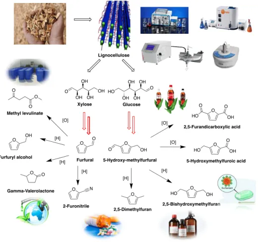
subject. The biomass downstream products from lignocellulosic materials, such as the furan compounds, since they are considered to have especially highly potential for the production of chemicals and fuels. Furfural (FF) and 5-hydroxymethylfurfural (HMF) as the most important and popular platform compounds which can be further transformed to more biomass based downstream products that have various industrial applications (Fig. 0.10).
Fig. 0.10. Synthesis and application of two platform molecules: Furfural and 5-Hydroxymethylfurfural.
Furfural (FF) (formula C5H4O2) is one of the oldest renewable chemicals, like
O OH OH OH OH HO Glucose O OH OH OH OH Xylose O O Furfural O O OH 5-Hydroxy-methylfurfural O OH Furfuryl alcohol O N 2-Furonitrile O 2,5-Dimethylfuran O HO OH 2,5-Bishydroxymethylfuran O O OH HO 5-Hydroxymethylfuroic acid O O HO O OH 2,5-Furandicarboxylic acid [O] [H] [H] [H] [H] [H] [O] [O] O O O Methyl levulinate O O Gamma-Valerolactone Lignocellulose
ethanol, acetic acid and sugar [18]. It could be found in many processed foods and beverages. The name of FF comes from the Latin word furfur, meaning bran, referring to its originally preparation from the co-heating of rice bran with dilute acid. FF is a colorless, transparent, oily liquid with a distinctive odor similar to benzaldehyde, but the color quickly changed when exposed to light and air, that’s why commercial samples are often amber. FF is the most important derivative of the furanic compounds, and it has high reactive activity due to its special function groups: aldehyde group and a dienyl ether group. The fundamental information of FF was listed in Table 0.2 [19].
Table 0.2. Fundamental information of furfural IUPAC
name Furan-2-carbaldehyde Appearance Colorless oil
Other names
Furfural, furan-2-carboxaldehyde, fural, furfuraldehyde, 2-furaldehyde, pyromucic
aldehyde Odor Almond-like Formula C5H4O2 Density 1.16 g/mL (20 °C) CAS Number 98-01-1 Boiling point 162 °C (324 °F; 435 K) EINECS Number 202-627-7 Solubility in water 83 g/L
Molar mass 96.09 g·mol−1 Vapor
pressure 2 mmHg (20 °C) Melting
point −37 °C (−35 °F; 236 K) Flash point
60 °C (144 °F; 335 K)
The first report was in 1821, German chemist Johann Wolfgang Döbereiner first discovered FF as a byproduct of formic acid synthesis. The Scottish chemist John Stenhouse found that FF could be produced by distilling a wide variety of crop materials, including corn, oats, bran, and sawdust, with aqueous sulfuric acid, he also determined an empirical formula of (C5H4O2) in 1840. Then, George Fownes named this oil FF in
1845. Later, German chemist Carl Harries deduced FF structure in 1901. QuakerOats Company first realized the industrialization of FF, which was mainly applied to the decolorization of wood rosin and the refining of lubricating oil, and realized the application of FF in the industrial field in 1922. Finally in the 1940s, FF was widely used in the fields of synthetic rubber, medicine, and pesticides. After the 1960s, with the development of FF derivatives, especially the widespread application of furan resins in the foundry industry, the development of FF industry was greatly promoted. FF was identified in 2004 as one of the top 30 high-value bio-based chemicals by the U.S. Department of Energy. FF was also an important organic chemical raw material, which can be used to prepare maleic anhydride, oxalic acid, decyl alcohol and tetrahydrofuran. It can also be used to synthesize FF resin, furan resin, rubber vulcanization accelerator, rubber anti-aging agent and preservative. FF is mainly used in medicine, pesticides, veterinary drugs, food as well.
Another important building block is 5-hydroxymethylfurfural (HMF) (formula C6H6O3), is an organic compounds formed by the dehydration of certain sugars [20].
HMF is a white low-melting solid (although commercial samples are often yellow); which is highly soluble in both water and organic solvents. The molecule consists of a furan ring, containing both aldehyde and alcohol functional groups. The fundamental information of HMF was listed in Table 0.3 [21].
Table 0.3. Fundamental information of 5-hydroxymethylfurfural
IUPAC name 5-(Hydroxymethyl)furan-2-carbaldehyde Appearance Yellow powder
Other names
(hydroxymethyl)-2-furaldehyde, (hydroxymethyl)-2-furancarbonal, 5-(hydroxymethyl)-2-furfural,
5-hydroxymethyl-2-formylfuran,
Odor chamomile flowers
Formula C6H6O3 Density 1.24 g/mL (25 °C)
CAS Number 67-47-0 Boiling point 116 °C (1 hPa)
EINECS
Number 200-654-9
Solubility in
water Freely
Molar mass 126.11 g·mol−1 Vapor
pressure
0.005 mmHg (25 °C)
Melting point 31.5 °C (88.7 °F; 304.65 K) Flash point 79 °C, closed cup
According to the Top Value Added of Energy, HMF is one of the top building block chemicals obtained from biomass [22]. The complex primary aromatic alcohol, an aldehyde, and a furan ring system can be transformed to 2,diformylfuran (DFF), 5-hydroxymethylfuroic acid (HMFCA), 5-formyl-2-furancarboxylic acid (FFCA), or 2,5-furandicarboxylic acid (FDCA) through oxidation reaction. FDCA is a monomer either to replace terephthalic acid in polyethylene terephthalate (PET) or to fabricate novel bioplastic materials, for example, polyethylene 2,5-furandicarboxylate (PEF) [23]. The annual market volume of FDCA is estimated at 200 kiloton in 2020 [24].
HMF hydrogenation can yield hydroxymethyl tetrahydrofurfural (HMTHF), 2,5-dihydroxymethyl furan (DHMF), or 2,5-2,5-dihydroxymethyl tetrahydrofuran (DHMTHF). The aldol condensation leads to the production of C7-C15 liquid alkanes, while rehydration gives levulinic and formic acid. It can also be used to synthesize a broad range of other value added compounds currently derived from petroleum [25]. Therefore, HMF has been called “a sleeping giant” [26], which means HMF with
infinity prosperity. However, the fully utilization of HMF deserved more deep investigation to realize HMF industrialization. It has already been used in the production of resins [27], but it has much greater potential as an intermediate for other 2,5-disubstituted furan derivatives. Such derivatives can be subsequently used in the production of fine chemicals, pharmaceuticals, polymers (polyesters, polyamides, or polyurethanes), solvents, or liquid transportation fuels [28-32].
The production of HMF, from carbohydrates has been reviewed regularly [33]. The first one was published by Newth [34]. During the rest of the 20th century, a number of reviews appeared. Lewkowski’s furan chemistry review, published in 2001, provides a comprehensive overview of the history of HMF synthesis and its fields of application [35]. In 2004, Moreau et al. updated this with a review on furan chemistry [36], followed by updates in 2010 by Ton [37]and 2011 by Rosatella [38], Lima [39], and Zakrzewska [40] reviewed the use of ionic liquids as green and benign solvents for selective sugar dehydration. A broader picture of biomass conversion into useful chemicals by Corma in 2007 [41] also included sugar dehydration and subsequent conversion of the furan products obtained in useful chemicals and polymers.
Therefore, the aim of this PhD work is to: 1) valorize FF and HMF into high value-added products, such as furfural alcohol (FA), methyl levulinate (ML), gamma-valerolactone (GVL), HMFCA and FDCA etc... Several key issues were identified in order to design processes greener than the current ones. Microwave irradiation has been chosen as the heating method to accelerate the reaction process in batch and continuous
flow processes. Flow reactors, such as Pheonix, H-cube Pro as well as microwave continuous flow with micro-reactor, were also identified as interesting alternatives to improve the productivities of target compounds.
The first chapter (Chapter I) reports the conversion of FA to ML in continuous flow with efficient zeolite (HZSM-5-50) as catalyst.
The second chapter (Chapter II) reports our contribution on the conversion of ML to produce GVL using heterogeneous 5% Ru/C as catalyst in continuous flow using iso-propanol as hydrogen donor.
The third chapter (Chapter III) reports HMF oxidation to HMFCA with silver oxide Ag2O as catalyst in both conventional heating and microwave heating method.
The forth chapter (Chapter IV) reports HMF oxidation to FDCA with 5% Ru/C in both microwave batch condition and microwave continuous flow condition.
The last chapter (Chapter V) mainly deals with the work we did starting for mucic acid) through dehydration to FDCA, and then use the under colbalt (II) acetate (Co(OAc)2 to synthesize FDCA based oligomers. Most importantly glycerol-FDCA
oligomer has been synthesized and first reported.
In the last part, after the concluding remarks, the supporting information will be added.
References
[1] J. N. Chheda, G. W. Huber, J. A Dumesic, Angew. Chem. Int. Ed. 46 (2007) 7164-7183.
[3] The Roadmap for Biomass Technologies in the U.S., Biomass R&D Technical Advisory Committee, US Department of Energy, Accession No. ADA 436527, 2002.
[4] F. Motasemi, M. T. Afzal, Renew. Sus. Energ. Rev. 28 (2013) 317-330.
[5] C. O. Kappe, A. Stadler, D. Dallinger, Microwaves in Organic and Medicinal Chemistry, John Wiley & Sons; 2006.
[6] D. A. Jones, T. P. Lelyveld, S. D. Mavrofidis, S. W. Kingman, N. J. Miles, Resour. Conserv. Recy. 34 (2002) 75-90.
[7] C. O. Kappe, Angew. Chem. Int. Ed. 43 (2004) 6250–6284.
[8] N. Kuhnert, Angew. Chem. Int. Ed. 41 (2002) 1863–1866.
[9] F. Chemat, E. Esveld, Chem. Eng. Technol. 24 (2001) 735–744.
[10] C. Shibata, T. Kashima, K. Ohuchi. Jpn. J. Appl. Phys. 35 (1996) 316–319. [11] B. Sajjadi, A. A. Aziz, S. Ibrahim, Renew. Sus. Energ. Rev. 37 (2014) 762-777. [12] J. Li, J. Dai, G. Liu, H. Zhang, Z. Gao, J. Fu, Y. He, Biomass Bioenergy 94
(2016) 228-244.
[13] R. Gedye, F. Smith, K. Westaway, H. Ali, L. Baldisera, L. Laberge, J. Rousell, Tetrahedron Lett. 27 (1986) 279-282.
[14] E. Grant, B. J. Halstead, Chem. Soc. Rev. 27 (1989) 213-224. [15] I. Bilecka, M. Niederberger, Nanoscale 8 (2010) 1358-1374.
[16] N. E. Leadbeater, Moseley in Microwave Heating as a Tool for Sustainable Chemistry 2017.
[18] F. N. Peters Jr. Ind. Eng. Chem. 28 (1936) 755-759. [19] Furfual. Wikipeidia.
[20] A. A. Rosatella, S. P. Simeonov, R. F. M. Frade, C. A. M. Afonso, Green Chem. 13 (2011) 754-793.
[21] 5-Hydroxymethylfurfural. Wikipeidia.
[22] T. A. Werpy, G. Petersen, Top value added chemicals from biomass; U.S. Department of Energy (DOE), Golden, CO, DOE/GO-102004 1992 2004. [23] R. De Clercq, M. Dusselier, B. F. Sels, Green Chem. 19 (2017) 5012-5040. [24] M. Sojid, X. Zhao, D. Liu, Green Chem. 20 (2018) 5427-5453.
[25] F. W. Lichtenthaler, Acc. Chem. Res.35 (2002) 728-737.
[26] M. Bicker, D. Kaiser, L. Ott, H. Vogel, J. Supercrit. Fluids 36 (2005) 118-126. [27] H. Koch, J. Pein, Polym. Bull. 13 (1985) 525-532.
[28] G. W. Huber, J. N. Chheda, C. J. Barrett, J. A. Dumesic, Science 308 (2005) 1446-1449.
[29] J. O. Metzger, Angew. Chem. Int. Ed. 45 (2006) 696-698. [30] J. N. Chheda, J. A. Dumesic, Catal. Today 123 (2007) 59-70.
[31] H. Mehdi, V. Fabos, R. Tuba, A. Bodor, L. T. Mika, I. T. Hrvath, Top Catal. 48 (2008) 49-54.
[32] E. L. Kunkes, D. A. Simonetti, R. M. West, J. C. Serrano-Ruiz, C. A. Gartner, J. A. Dumestic, Science 322 (2008) 417-421.
[33] F. Delbecq, C. Len. Molecules 23 (2018) 1973-1988. [34] F. H. Newth, Adv. Carbohydr. Chem. 6 (1951) 83-106.
[35] J. Lewkowski, J. ARKIVOC 2001 (2005) 17-54.
[36] C. Moreau, M. N. Belgacem, A. Gandini, Top. Catal. 27 (2004) 11-30. [37] X. Tong, Y. Ma, Y. Li, Appl. Catal. A 385 (2010) 1-13.
[38] A. Rosatella, S. P. Simeonov, R. F. M. Frade, C. A. M. Afonso, Green Chem. 13 (2011) 754-793.
[39] S. Lima, M. M. Antunes, M. Pillinger, A. A. Valente, CHEMCATCHEM 3 (2011) 1686-1706.
[40] M. E. Zakrzewska, E. Bogel-Łukasik, R. Bogel-Łukasik, Chem. Rev. 110 (2010) 397-417.
Chapter 1. Alcoholysis of furfuryl alcohol to
alkyl levulinates using zeolites in continuous
flow
1.1. Abstract
The present work explores the catalytic activity of various zeolites for the production of methyl levulinates (ML) from hemicellulose derived furfuryl alcohol (FA) and explores the performance of H-ZSM-5-50 zeolite in continuous flow alcoholysis. ML yields up to 80 % were achieved at 170 °C (50 bar) using a high load (1.6 M FA) feed at 0.2 mL min-1 flow rate. Angelica lactones were produced in significant amounts
as one of the side products, albeit in lower amounts in continuous flow mode. Catalyst deactivation occurred at high FA load through formation of pore blocking polyfurfuryl alcohols. The zeolites showed good re-usability after regeneration at 500 °C. The levulinates yields in ethanol and n-propanol were 20 % lower.
1.2. Introduction
Recent advances in the field of catalytic valorization of lignocellulose for the production of biofuels and chemicals aim to reach high yields of 5-hydroxymethylfurfural (HMF) through isomerization and dehydration of glucose or oligomers, produced from cellulose hydrolysis [1, 2]. Furfural (FF) can be produced from xylose, as the major hydrolysis product from hemicelluloses [3, 4]. Levulinic acid (LA) is among the top target chemicals in lignocellulose biorefinery and it can be
converted into various derivatives with several applications, particularly into alkyl levulinates (AL) as biofuel additive or precursor [5]. AL can be obtained via esterification of LA with various alcohols [6]. LA can be produced directly from various biomass sources in acidic aqueous media, but this process deals with the production of waste, a high cost for mineral acid recovery, humin formation and a rather difficult separation of the highly polar molecule LA [7, 8]. Some promising results were obtained using ionic liquids and with the carbohydrate derived solvent γ-valerolactone (GVL), and by using solid acid catalysts, like demonstrated recently for H-ZSM-5 in aqueous THF [9]. Alcoholysis is a promising alternative to tackle these problems and opens ways for direct conversion of sugar monomers [10, 11], like demonstrated very recently for ML starting from glucose using sulfated zirconia [12]. The alcoholysis processes can also be started from HMF (Scheme 1.1, pathway displayed in green), without the need for isolation of LA from aqueous product streams. Likewise, AL can also be produced via selective hydrogenation of FF to FA followed by conversion in various alcohols (ROH), as illustrated in Scheme 1.1 (pathway displayed in blue). This conversion allows to increase the overall yield of a levulinate production plant from lignocellulose by converting a minor co-product, FF or FA, into its main product.
Scheme 1. 1. Production of biomass derived alkyl levulinates via (a) esterification of levulinic acid, (b) alcoholysis of 5-hydroxymethylfurfuryl alcohol (in green) and (c) alcoholysis of furfuryl alcohol (in blue).
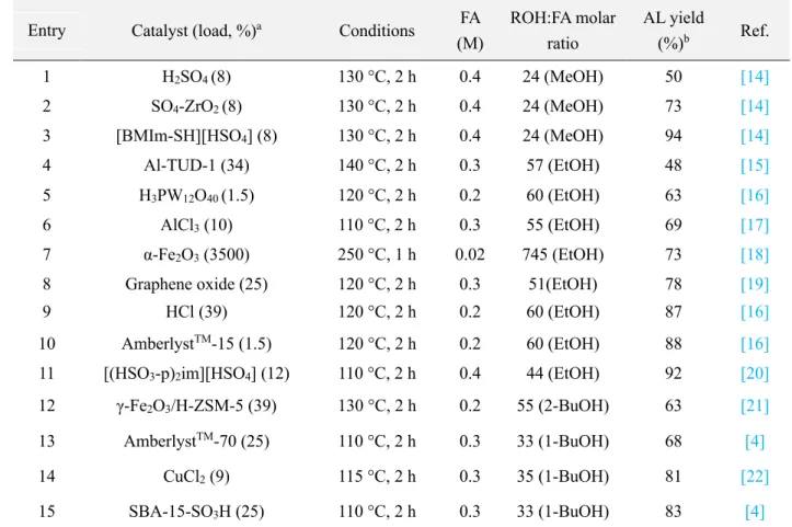
Various solid acid catalysts have been demonstrated to work pretty fine for the conversion of FA to AL, as recently reviewed for ethyl levulinate (EL) by Haider and co-workers [11]. The AL yield increases with higher reaction temperature, higher catalyst dosage, longer reaction time and lower FA load. Considerable time laps were observed between FA conversion and the formation of AL, as multiple reaction intermediates are formed in the alcoholysis [13]. A series of side products can be formed, originating from the reactants and intermediates. One particular side product is polyfurfuryl alcohol, which may cause pore blocking and occupation of the catalytic
site. The formation of this oligomeric/polymeric side product can be suppressed by operating at moderate temperatures and reducing the reaction time. Most of the research studies on FA alcoholysis operated at temperatures between 110 and 140 °C [4, 14-18, 20-22], with some exceptions at 80 °C [19]. Although strongly depending on the catalyst load and the alcohol chain length, most of the studies required at least 2 h to attain full conversion and typically 2-6 h to obtain high AL yields using 0.2-0.4 M feedstocks, with some exceptions in 60 min [18, 21]. Table 1.1 compares the activity of the most promising solid acid catalysts reported for the conversion of FA to methyl-, ethyl- and butyl levulinate after 2 h reaction. Acidic ionic liquids (Table 1.1, entries 3 and 11) are among the most efficient catalysts, but the environmental impact resulting from their use today still remains not fully clear. Commercial catalysts such as AmberlystTM (Table 1.1, entries 10 and 13) and α-Fe
2O3 (Table 1.1, entry 7) performed
also well, although high temperature is required when using α-Fe2O3. Catalysts
decorated with sulfonic acid groups were also reported in several occasions; SBA-15-SO3H (Table 1.1, entry 15) was found to be the best performing catalyst, at least for
the alcoholysis in 1-butanol (butyl levulinate). Various metal chloride salts, including AlCl3 (Table 1.1, entry 6), CuCl2 (Table 1.1, entry 14) but also FeCl3, showed very
promising results, although their recovery by filtration may result costly or less efficient (metal leaching) [22]. Sulfated zircona dioxide (Table 1.1, entry 2) and titanium dioxide are also catalyst candidates [14].
Table 1. 1. Acid catalysts reported for the conversion of FA to AL
Entry Catalyst (load, %)a Conditions FA
(M) ROH:FA molar ratio AL yield (%)b Ref. 1 H2SO4 (8) 130 °C, 2 h 0.4 24 (MeOH) 50 [14] 2 SO4-ZrO2 (8) 130 °C, 2 h 0.4 24 (MeOH) 73 [14] 3 [BMIm-SH][HSO4] (8) 130 °C, 2 h 0.4 24 (MeOH) 94 [14] 4 Al-TUD-1 (34) 140 °C, 2 h 0.3 57 (EtOH) 48 [15] 5 H3PW12O40 (1.5) 120 °C, 2 h 0.2 60 (EtOH) 63 [16] 6 AlCl3 (10) 110 °C, 2 h 0.3 55 (EtOH) 69 [17] 7 α-Fe2O3 (3500) 250 °C, 1 h 0.02 745 (EtOH) 73 [18]
8 Graphene oxide (25) 120 °C, 2 h 0.3 51(EtOH) 78 [19]
9 HCl (39) 120 °C, 2 h 0.2 60 (EtOH) 87 [16]
10 AmberlystTM-15 (1.5) 120 °C, 2 h 0.2 60 (EtOH) 88 [16]
11 [(HSO3-p)2im][HSO4] (12) 110 °C, 2 h 0.4 44 (EtOH) 92 [20]
12 γ-Fe2O3/H-ZSM-5 (39) 130 °C, 2 h 0.2 55 (2-BuOH) 63 [21]
13 AmberlystTM-70 (25) 110 °C, 2 h 0.3 33 (1-BuOH) 68 [4]
14 CuCl2 (9) 115 °C, 2 h 0.3 35 (1-BuOH) 81 [22]
15 SBA-15-SO3H (25) 110 °C, 2 h 0.3 33 (1-BuOH) 83 [4]
a Weight percentage on FA load; b molar percentage
All the experiments reported in the literature on FA conversion to AL were performed in batch reactors. Haan and co-workers produced EL in semi-batch mode as a strategy to overcome polyfurfuryl alcohol side product formation, by feeding the FA slowly to the batch reactor [23]. To the best of our knowledge, only one recent study from 2017 reported the continuous flow alcoholysis of FA [24]. More research is required here, not only because of the already known advantages of continuous flow reactors such as better mass transfer, but also because it is likely that FA feedstocks will be produced by selective continuous flow hydrogenation of FF [25], because FF itself can also be produced in relatively high yields in continuous flow [26-28] and
because it may lower the formation of polyfurfuryl alcohol side products and humin as well. The present study explores various zeolites for the conversion of FA to ML and studies the behavior in continuous flow using a catalytic bed packed with the best performing zeolite. The alcoholysis in ethanol and n-propanol was also demonstrated.
1.3. Experiment section
1.3.1. Materials, solvents and reagents
Furfuryl alchohol (FA, ≥ 98 %), methanol (MeOH, ≥ 99.9 %), ethanol (EtOH, ≥ 99.5 %), n-propanol (n-PrOH, ≥ 99.5 %), methyl levulinate (ML, 99 %), γ-valerolactone (GVL, 99 %) and n-decane (≥ 99 %) were purchased from Sigma-Aldrich and further used without purification. FA feedstocks of 0.1, 0.2, 0.4, 0.8 and 1.6 M were prepared by dissolving 0.993, 1.985, 3.979, 7.936 and 15.882 g FA in 100 mL alcohol in a volumetric flask using n-decane (5.0 mg/mL) as external standard. The commercial MFI (Mobil type five) zeolites CBV3024E and CBV5524G (5-30 and H-ZSM-5-50 with SiO2/Al2O3 molar ratios 30 and 50, respectively) and FAU (Faujasite) zeolites
CBV500 and CBV760 (H-Y-5.2 and H-Y-60 with SiO2/Al2O3 molar ratios 5.2 and 60,
respectively) were purchased from Zeolytes International (USA).
1.3.2. Catalyst synthesis and characterization
The commercial zeolite catalysts were calcined at 600 °C during 24 h prior to use in the catalytic experiments.
![Table 1.3. Si/Al ratio and acidic properties of H-ZSM-5 and H-Y zeolites [35]](https://thumb-eu.123doks.com/thumbv2/123doknet/14528189.723171/56.892.140.763.661.924/table-si-al-ratio-acidic-properties-zsm-zeolites.webp)