HAL Id: hal-00187735
https://hal.archives-ouvertes.fr/hal-00187735
Submitted on 15 Nov 2007
HAL is a multi-disciplinary open access
archive for the deposit and dissemination of
sci-entific research documents, whether they are
pub-lished or not. The documents may come from
teaching and research institutions in France or
abroad, or from public or private research centers.
L’archive ouverte pluridisciplinaire HAL, est
destinée au dépôt et à la diffusion de documents
scientifiques de niveau recherche, publiés ou non,
émanant des établissements d’enseignement et de
recherche français ou étrangers, des laboratoires
publics ou privés.
Comparison of two modulation techniques using
frequency domain processing for in-house networks
Geert Carron, Reto Ness, Luc Deneire, L. van der Perre, M.G.E. Engels
To cite this version:
Geert Carron, Reto Ness, Luc Deneire, L. van der Perre, M.G.E. Engels. Comparison of two
mod-ulation techniques using frequency domain processing for in-house networks. IEEE Transactions
on Consumer Electronics, Institute of Electrical and Electronics Engineers, 2001, 47 (1), pp.63-72.
�10.1109/30.920421�. �hal-00187735�
Carron et al.: Comparison of Two Modulation Techniques Using Frequency Domain Processing for In-House Nethorks 63
COMPARISON OF TWO MODULATION TECHNIQUES USING FREQUENCY DOMAIN
Geert Carron, Reto Ness, Luc Deneire, Liesbet Van der Perre and Marc Engels{carron, deneire, vdperre, engelsm}@imec.be
Interuniversity Micro Electronics Center (IMEC)
-
Kapeldreef 75, 3001 Heverlee, BelgiumPROCESSING FOR IN-HOUSE NETWORKS
ABSTRACT
Recently, the industry has shown a growing interest in the field of in-house wireless communication. The two major technical challenges are the interference and the signal distortion by the communication channel. We pro- pose three different interference mitigation and distor- tion compensation strategies. These strategies are based on frequency domain processing, which is best supported by Orthogonal Frequency Division Multiplexing (OFDM) and Single-Carrier modulation with cyclic prefix (SC-
CP). Both modulation techniques are compared with re- spect to their performance in an in-house environment.
Both techniques are promising for in-house communi-
cation in an environment corrupted by interference and frequency selective channels.
1 Introduction
Wireless digital communication in indoor environments is gaining interest of customers and industry. The performance of wireless indoor networks is however limited by the com- munication channel, which distorts the signal due to reflec- tions and scattering. This channel distortion must be com- pensated such that a high data-throughput is reachable while keeping the system cost moderate. The compensation is per- formed by a channel equalizer. When the equalization is per- formed in the time domain, it requires a very complex block, such as a Viterbi equalizer. To avoid this complex block, we propose to do the equalization in the frequency domain. Another way ofreducing the system cost is using the 2.4 GHz
license-free Industrial, Scientific and Medical (ISM) band. However, as more systems make use of this ISM-band, an increasing level of mutual interference is generated. On top of this, the 2.4 GHz band is corrupted by energy leakage of
microwave ovens. A reliable Communication system must also compensate this impairment.
This paper compares two systems that have interesting prop- erties for wireless in-house communication : Orthogonal Fre- quency Division Multiplexing (OFDM) and Single Carrier modulation with cyclic prefix (SC-CP). OFDM is the modu- lation technique chosen in most of the current in-house com- munication standards. This modulation technique requires less digital complexity compared with the SC-CP technique,
but has two major drawbacks : the OFDM-signal is char- acterized by a high peak-to-average and the system puts a high requirement on the frequency synchronization at the re- ceiver. On top of the multipath-fading channel, two types of interference are used : the Bluetooth communication system and the microwave oven. Three interference mitigation tech- niques are introduced : adaptive loading and spreading with maximal-ratio combining for OFDM, and FRequency SHift (FRESH) filtering in the frequency-domain for SC-CP. The results show that both systems
are
able to setup a suc- cessful high-speed communication in an in-house environ- ment with static interference. Although OFDM requires less digital complexity, the OFDM signal properties require more analog complexity. Therefore, a trade-off between both sys- tems must be made on a higher system-level including all the digital and analog aspects.Section two introduces the channel model, the modulation techniques and compares their performance in a multipath channel. Section three derives the interference models while section four details thc mitigation techniques and their per- formance.
2 System Models
In this section, we first introduce the channel model we used to evaluate the system performances. The following two parts present the two modulation techniques, OFDM and SC-CP. In a fourth part, we compare both techniques on a system level and present performance results for both sys- tems.
2.1 Channel Model
A reliable model for the transmission channel is needed to analyze the performance of the different modulation tech- niques in an in-house environment. We have implemented a ray-tracing model[ 11 that generates the frequency- or time domain response of an indoor environment based on the ge- ometrical layout of this environment. The ray-tracing pro- gram computes all paths from a transmitter to a receiver, taking the different reflections into account, until the total path attenuation has reached a predefined value. The length and the attenuation of the differcnt paths is then used to compute the time- and frequency domain response. These
Original manuscript received June 19, 2000
64 IEEE Transactions on Consumer Electronics, Vol. 47, No. 1, FEBRUARY 2001
ray-tracing simulations show us that the in-house channel is characterized by a RMS-delay spread ZRMS of 5 to 20 ns. The frequency-domain channel responses show frequency- dips of up to 30 dB. We have used this model to generate 120 different in-house channel responses, which we used to perform the multipath performance simulations.
2.2 The OFDM System
The OFDM-system is a special case of multi-carrier trans- mission. In this kind of transmission systems, the signal bandwidth W is subdivided in a number of sub-bands Nc.
Each sub-band is used to transmit l/Nc-th of the data. In a normal multi-carrier transmission system, the N, sub-bands are completely separated, such that no Inter-Carrier Interfer- ence (ICI) exists. In OFDM, IC1 is avoided by using orthog- onal subcarriers : J:~i(t)sj(t)dt = 6ij. At the receiver, we can reconstruct the data by sampling the received signal in the frequency-domain at the correct carrier frequencies. Fig- ure l(a) depicts the block diagram of an OFDM system. At the transmitter, complex constellation symbols, called data- symbols, are generated from the data. These symbols are used to modulate the different sub-carriers. The modula- tion and frequency-spacing is automatically performed by passing the complex constellation symbols through an In-
verse Fast Fourier transform (IFFT). Afterwards, the output- samples of the IFFT are multiplexed into an OFDM-symbol. A copy of the last Ng samples of the OFDM symbol, called
a cyclic-Prefix (CP), is prepended to each OFDM-symbol. This CP has two purposes : first it serves as a guard-interval between the different OFDM-symbols and secondly it trans- forms the OFDM-signal into a pseudo-cyclic signal. The guard-interval serves as a buffer between subsequent OFDM- symbols so that no Intersymbol Interference (ISI) is gener- ated. All the echoes of one OFDM-symbol will fall in the CP of the next OFDM-symbol. At the receiver, the CP is removed and so is the ISI. The pseudo-cyclic signal has an important property that largely reduces the complexity of the receiver.
After the OFDM-symbol is multiplexed and a CP is prepen- ded, the signal is transmitted over the indoor channel where noise and interference is added. At the receiver, the CP is
removed and the OFDM-symbols are demultiplexed again. The sub-carriers are demodulated again into complex con- stellation points by applying a Fast Fourier Transform (FFT). This operation transforms the signal back to the frequency domain, were we perform the channel equalization, interfer- ence mitigation and data-detection. The channel-equalization effort is largely reduced by adding the CP. An equalizer- block compensates for the channel distortion. This channel- distortion means that the transmitted signal is linearly con- voluted with the time-domain impulse response of the chan- nel. However, from digital signal processing theory ([2], page 415) we know that a cyclic convolution in the time- domain is transformed into a simple multiplication in the
frequency-domain. By introducing the CP, we have gen- erated a pseudo-cyclic signal and thereby transformed the linear channel-convolution into a cyclic convolution. As a
result, the complex time-domain equalizer is replaced by a simple multiplication in the frequency-domain for every sub- carrier.
2.3 The SC-CP System
The single-carrier system with cyclic prefix depicted in Fig- ure l(b) aims to combine thc advantages of the frequency- domain processing of OFDM, such as the reduced equalizer complexity, with the advantages of single-carrier transmis- sion, such as the better peak-to-average ratio. The com- plexity of the equalizer is reduced by grouping the data- symbols into fixed-length block-symbols and insert a CP be- tween these block-symbols. The CP avoids IS1 and trans- forms the signal in a pseudo-cyclic signal. The block-sym- bols are multiplexed and transmitted over the channel. Noise and interference is added and the receiver demultiplexes the blocks again. Then, the CP is removed and the block-sym- bols are transformed to the frequency-domain to perform equalization and interference mitigation. Finally, the block- symbols are retransformed to the time domain for data de- tection.
2.4 System Comparison
The two modulation techniques presented above have differ- ent signal properties. OFDM is in essence a multi-carrier modulation scheme, while SC-CP is a single-carrier modu- lation technique. This difference will have an implication on the performance of both systems and the requirements for the analog front-ends. This subsection discusses three important consequences.
A first consequence is the different behaviour of both sys- tems in a multipath environment. This environment will se- lectively attenuate the signal on certain frequencies. For SC- CP, the selective attenuation results in a small energy loss for all transmitted data and thus a proportional reduced detection reliability. In the OFDM case, this selective attenuation will result in an almost complete information loss on certain sub- carriers. This analysis suggests that an OFDM-system will perform worse than a single-carrier system, which is con- firmed by the simulation results presented in Figure 2. This figure plots the Bit Error Rate (BER) with respect to Eh/No, which is the average bit energy divided by the double-sided spectral noise density. This difference disappears when we take Forward Error Coding and interleaving into account. By doing so, we introduce frequency diversity into the sig- nal. This makes the OFDM-system equally performant as the single-carrier system.
A second consequence concerns the peak-to-average prop- erty of the transmitted signal. The signals on the different subcarriers in an OFDM-system have an uncorrelated phase. When all the subcarriers are in-phase, the OFDM-system
Carron et ai.: Comparison of Two Modulation Techniques Using Frequency Domain Processing for In-House Networks
L.
'%}Ng 4 .
(a)OFDM (b) SC-CP
Figure 1 : Single carrier transmission moves the processing to the receiver-part
x sc-CP
-
OFDM + SC-CP + FEC + OFDM t FEC 100.
a. eFigure 2: OFDM needs special attention, to compensate for
multipath fading
will show a high output value. On the other hand, when half of the subcarrier signals are in opposite phase with the other half, they will compensate each other and the output signal will have a low amplitude. Transmitting and receiving such signal requires an analog front-end with a high dynamic range and thus a low efficiency.
A third consequence involves frequency synchronization. At
the receiver, the local oscillator must be synchronized within a fraction of the bandwidth. With OFDM however, this means a fraction of a subband, which is a factor l / N c smaller than the signal bandwidth. This puts a higher constraint on the local oscillator circuitry of the receiver.
3 Interference Models
In the previous section, we have introduced two modula- tion techniques suitable for indoor communication. We have evaluated their performance in terms of BER over a multi- path fading channel. However, a communication system also has to cope with different kinds of interference, mainly gen-
erated by other communication systems and/or other elec- tronic equipment. The 2.4 GHz ISM band in particular has to cope with interference generated by Bluetooth and mi- crowave ovens. In this section, we will introduce the two baseband models we developed for Bluetooth and microwave oven interference.
3.1 The Bluetooth Model
The system described in this paper is not the only commer- cial communication system using the ISM-band. One par- ticular system that is believed to become a very widespread 2.4 GHz system in the near future, is Bluetooth[3]. In or- der to analyze our system in the presence of a Bluetooth- interferer, we have implemented a general model for such an interferer[4]. The Bluetooth-system makes use of Frequency- Hopping Spread-Spectrum (FH-SS) to transmit data. The carriers are modulated with a Continuous-Phase Frequency Shift Keyed signal (CP-FSK). In the model, a random se-
quence of ASK-symbols represent the data and a time vary- ing carrierf,(t) isused to model the frequency-hopping. The general form of the interferer is given by :
i.w(t) = 2~ cos 2nh(t)t
+
xm [== ci(r)ciT) (1)+==
(
with d ( t ) = f n l l r ( t - n T ) n=--
where Z, represents the data sequence and n(t) is a rectan- gular window.
1 i f O < t < T
n T ( t ) =
{
0 otherwiseThe modulation index of the CP-FSK signal of Equation (1)
is given by :
m =
2TAf
in which
T
is the symbol-duration andA
f
the minimum fre- quency distance between two modulated symbols.66 IEEE Transactions on Consumer Electronics, Vol. 47, No. 1, FEBRUARY 2001
The time-varying carrier frequency is expressed as follows :
k+-
fc(4
= m q , , , (t-
m o p ) (3)k=--
with Fk the hopping-sequence.
We use this interference model with the parameters as listed in Table 1 to generate a Bluetooth interference signal. The Bluetooth-system is characterized by a data-rate of up to
1 Mbps. The instantaneous bandwidth is I MHz. This signal
is hopping over 79 different hopping frequencies at a rate of
1600 hops/s. The different hopping frequencies are spaced
apart by 1 MHz and range from 2.402 GHz to 2.48 GIlz.
Figure 3 depicts the spectrum of a Bluetooth system as it is computed by our model.
Random BPSK-sequence, I, E {
-
1,+
1 }0.3 6 2 5 p
{2.402GHz, 2.403GHz, .
. .
,2.48GHz} randomlyshuffled and periodically extended
2.44GHz 1P
1
/&
Table 1: The Bluetooth-system as a special case of the gen- eral interference model
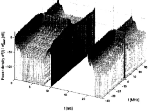
during one half of the period of the line-voltage the inter- ference is absent; during the other half the interference is
present. At the beginning of the on-phase, the microwave oven generates a broadband signal which soon transforms in a relative narrowband signal with a central frequency under
2.45 GHz. Progressively, this signal becomes narrower in
bandwidth and the central frequency evolves towards
2.45 GHz, which is the design frequency of a microwave oven. Once the design frequency is reached, the signal re- mains stable at this frequency with a bandwidth of 1 MHz.
At the end of the on-phase, the interference signal traverses the same traject in the opposite direction.
""
-40 IIMHZI I lmgl
Figure 4: One cycle of a microwave oven spectrum
t lh81
Figure 3: A Bluetooth-interference hops through the ISM- band
3.2
Based on the physical properties of a microwave oven[5], a model for the interference of this device was derived. The spectral properties of this signal are depicted in Figure 4. In
this figure, the spectrum is shifted over the design-frequency of the microwave oven. Two different phases are present :
The Microwave Oven Emission Model
4 Interference Mitigation Strategies
An indoor communication system suffering from interfer- ence will show a largely degraded performance. In case of narrowband interference, the energy of the interfering signal drowns the energy of the desired signal in a part of the sig- nal bandwidth. The influence this has on a communication system depends on the type of modulation used and inter- ference mitigation strategy applied. This section introduces three interference mitigating strategies for the two modula- tion techniques introduced in section 2.
4.1 OFDM
Narrowband interference, added to a multicamer signal such as OFDM, will corrupt the information transmitted on the af- fected subcarriers. Every subcarrier transmits on the average l/Nc-th of the total transmitted energy, with Nc the number of subcarriers. If the interference energy is concentrated on a few of those subcarriers, it drowns the useful signal and thereby destroys the information on those carriers. This re- sults in a flooring-effect of the BER vs. &,/No since the transmission errors are no longer caused by the noise, but rather by the interference (Figure 5).
Carron et al.: Comparison of Two Modulation Techniques Using Frequency Domain Processing for In-House Networks 61
Figure 5 : Interference causes a floor of the BER perfor- mance
We propose three interference mitigation strategies that will also avoid or compensate for multipath fading effects, which are similar to the effects of interference in the sense that they also destroy the information on a number of subcarriers.
4.1.1 Aduptive Loading
Due to multipath fading and interference, there is a large dif- ference in transmit capacity between the OFDM subcarriers. The overall system performance is limited by the worst per- forming subcarrier. To avoid this limitation, we can opti- mize the transmitted information on each subcarrier towards the information capacity of that subcarrier. This capacity is determined by the noise and interference power received on the subcarrier. The technique which implements this opti- mization is called adaptive loading. It has already success- fully been used in the Asynchronous Digital Subscriber Line (ADSL) technology and is gaining interest in the field of Wireless Local Area Networks (WLAN) [6]. We are per- forming extensive research on this technique and are con- sidering it also for interference mitigation. Figure 6 shows the principle of adaptive loading. Subfigure (a) shows a typ- ical frequency response of an indoor channel with a fading dip of 30 dB. Subfigure (b) shows an example of the power distribution of a narrowband interferer with a peak-power of 14 dB above the noise level. Subfigure (c) and (d) respec- tively show the rate distribution and the power distribution over the different subcarriers. It is clearly shown that the most affected subcarriers are not carrying any data. Subfig- ure (e) shows how the Signal to Noise and Interference Ratio (SINR) is almost equally spread over the available subcarri- ers. In a non-adaptive transmission system, the rate and the transmit power would equally be distributed over all avail- able subcarriers. Since nature does not equally spread noise and intcrference, this results in large SINR differences be- tween the subcarriers. Finally we can see in subfigure (f)
how the BER is flattened over the different useful subcarri- ers. Chow, Cioffi and Bingham have proposed an algorithm yielding the optimal distribution of transmit power and trans- mission rates over the available subcarriers[7]. The optimal transmission rate for eyery subcarrier, R k , is directly deter- mined by Equation (4).
r
is an iteratively determined parameter which makes &Rk = R,,, with RtOf the predefined number of information bits assigned to one OFDM-symbol. J. Fisher and J. Huber proposed a bit loading algorithm based on this strategy[b]. In this algorithm, the carrier rates are iteratively computed until the desired rate Rro, is reached. The algorithm takes thefollowing parameters as an input : the subcarrier channel re- sponse hk, the subcarrier noise plus interference power Nlk,
the total number of bits per OFDM-symbol Rro, and the total transmit power St,,. r- r I 50 60 , I 20 30 60 IO ' 0 20 Jo 40 M 60 Carrier index k
Figure 6: Adaptive loading optimizes the overall system per- formance
68 IEEE Transactions on Consumer Electronics, Vol. 47, No. 1, FEBRUARY 2001
are measured at the receiver and fed back to the transmitter. In our simulations, this is done during a silent phase with a duration of 10 OFDM-symbols. Since h k and NIk cannot be updated during transmission, the adaptive loading sys- tem assumes a quasi-static channel response and interferer. This immediately indicates one of the major drawbacks of the system, i.e. the technique cannot track dynamic interfer- ence sufficiently.
4.1.2 Spreading
One of the drawbacks of the adaptive loading scheme is that channel and interference update information must be fed back periodically from the receiver to the transmitter. Therefore, this system will only work properly in a quasi-static environ- ment. In the case of a Bluetooth hopping interferer, a com- plete transmitted block can be lost when the Bluetooth signal hops just after the update-phase of the parameters. Another drawback is that adaptive loading only works for point-to- point connections and does not support broadcasting. There- fore we implemented a second interference mitigation strat- egy which does not have these drawbacks. This technique exploits frequency diversity by applying Direct Sequence Spreading (DSS) in the frequency-domain. This technique is based on a strategy proposed by K. Fazel [9] which we
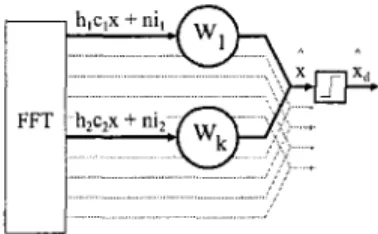
have improved. The idea is to transmit the same data over multiple carriers in such way that the frequency separation is maximized. At the receiver, both copies of the data are then recombined in an optimal way, as is shown in Figure 7. Whenever narrowband interference or multipath fading af- fects one subcamer, this data can still be retrieved by using its copy from another subcarrier. The receiver performs the despreading by using an estimate of the SINR of the received signal. This estimate is used to compute the weighting-factor by which the signal of each subcarrier must be rescaled such that the recombined signal results in a maximized detection probability. We can write the estimate of the received bit as follows : L kl xA = W k ( h k C k X + n i k ) L L = X Wkhkck
-+
Wknik ( 5 ) n= I k= Iin which wk represent the weighting factor, h k the appropri- ate channel frequency response and Ck the spreading code.
n i k Represents the noise plus interference on the kth sub- carrier. The optimal weighting factors are computed with Equation (6) :
This maximum-ratio combining requires an estimate of both the channel coefficients and the average noise-and-interfe- rence power (NI) on the subcamers. The channel coeffi- cients can be reused from the equalization unit. The original
implementation from K. Fazel used zero-pilots to compute an estimate for NI. These zero-pilots reduce the bandwidth- efficiency of the system. To avoid this, we have replaced these zero-pilots by an estimator based on decision feedback. This estimator maintains the system performance and does not reduce the systems bandwidth efficiency.
... .... . . .. . . . ... .. .
Figure 7: Optimal combining increases the system perfor-
mance
4.2 SC-CP
In the previous section, we have introduced two interfer- ence mitigation strategies for an OFDM-transmission sys- tem. The multi-carrier property of OFDM enables us to ap- ply an interference-mitigating strategy independently for ev- ery subcarrier and thus for every transmitted data-symbol. This property is the biggest difference between interference mitigation in an OFDM-system and in a SC-CP-system. In the latter case, the energy of every transmitted bit is spread over the complete signal bandwidth. Every impairment within this bandwidth will thus have its impact on every transmitted symbol. Since it is not possible to avoid the transmission of information in a certain part of the bandwidth, the mitiga- tion strategy is aiming at ignoring the affected frequencies and reconstructing the corrupted signal.
4.2.1 FRESH-filtering
The interference mitigation strategy we propose for the SC- CP modulation technique is based on a technique introduced by W.A. Gatdner[ IO]. This technique uses the spectral cor- relation property of a signal transmitted with an excess band- width. This excess bandwidth introduces frequency diversity by transmitting one or more spectral images of the signal. A
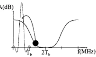
correlation exists between the signal and a fixed predefined frequency-shifted copy of the signal or its complex conju- gate. The frequency-shifts over which this correlation occurs depend on the type of modulation used, but is always a linear combination of the baudrate, the carrier frequency or both. In case of QPSK-modulation or higher QAM-constellations, correlation occurs only for linear combinations over the bau- drate. A list of frequency correlations is published in[lO]. We can now use the frequency correlation property of the signal to correct the distortion generated by the interference. This principle is depicted in Figure 8. First we have to gen-
Carron et al.: Comparison of Two Modulation Techniques Using Frequency Domain Processing for In-House Networks 69
Figure 8: Frequency correlation can be used to correct the corrupted signal
erate all the frequency-shifted versions of the input-signal. Then we apply a Linear Time-Invariant filtering-operation (LTI) on all these signals and finally we combine all the re-
sults to generate the corrected signal. This complete opera- tion is called FRequency SHifted filtering (FRESH-filtering). The filters used are computed in such a way that the over- all performance is optimizcd. We can write the signal after FRESH-filtering as follows[ 1 11 :
i ( t ) = wHy(t) (7)
Here, w corresponds to the Least Square (LS) coefficients of the LTI-filters minimizing the average-squared error, ( l i ( t ) -
s ( t ) l 2 ) . The transmitted data-sequence is s ( t ) and ?(t) is the estimate of the transmitted data-sequence at the receiver. The definition of y is as follows :
A
Y(t) = [Pa0 (1 - t l ) .
.
.Pa&-
tm)...
PaL-,
( t - t l ) . . . P a L 4tf--t,)
P-pa(t -t1)* ..-P-po(t- t m ) *P-p,~,(t-tl)*.--P-p,-,(t-tm)*lT (8)
A .
in which p p = r(t)eJ2'Pt which is a frequency-shiftedversion of the received signal r ( t ) , t k are delays chosen such that the designed filters are causal. The LS-coefficients w are now computed as follows :
w =
d-'R
YY ys
ri,,
= C Y ( t ) . f ( t N NRys = b ( t b * ( t ) ) N (9) with ( . ) N a time averaging overN samplcs andf(t) denotes the complex conjugate transposition.
We have implemented a system with an excess bandwidth of
100% and 16-QAM as modulation technique. This means that we have a correlation available between three differ- ent frequency-shifts, namely r ( t ) , r(t)ei2'fIt and r(t)e-i2xflt
with fl thc baudrate of the signal. The data-stream is sub-
divided into blocks of 8000 bits and a training sequence is
transmitted before every block. This sequence is used to ini- tialize the filter coefficients. The FRESH-filter coefficients are computed in the time-domain using Equation (9) and afterwards transformed to the frequency-domain using the FFT-algorithm .
The LS-coefficicnts computed with Equation (9) will mini- mize the mean-squared error between the received signal and the training signal. This error can either be caused by in- terference or by multipath fading. FRESH-filtering will not only compensate for interference, but also for the channel- impairments. There is thus no need for an extra equalization step.
In order to successfully use FRESH-filtering for interference- cancellation, we have to avoid spectral leakage of the inter- fering signal. At the transmitter, we have constructed a data- signal which is pseudo-cyclic. This property is important because it reduces all filtering operations in the receiver to a complex multiplication in the frequency-domain. A prob- lem occurs however when an interference-signal is added to the data-signal. This interfering signal is not cyclic. An FFT-transformation from a non-cyclic signal will result in a
spectral leakage[2]. This leakage will result in an increased signal distortion. The undesired spectral interference side- lobes are not yet present when the FRESH-coefficients are computed. The extra impairment will thus not be removed by the FRESH-filters and the systcm performance will de- crease. Sincc the iinpairmcnt is caused by the non-cyclic behaviour of the interference, it will have its biggest impact at the borders of the block-symbols. To avoid extra trans- mission errors, we have introduced a small silent-phase at the beginning and end of every block-symbol. This is equiv- alent to the zero-carriers which are introduced in an OFDM- symbol to avoid spectral out-of-band leakage.
4.3 performance comparison of OFDM and SC-CP dis-
torted by interference
This subsection presents the performance of both simula- tion techniqucs when affcctcd by the narrowband intcrfer- ence as described in section 3.1 and section 3.2. The trans-
mission rate of both systems was fixed at 20 Mbps with
a signal bandwidth of I O MHz. The simulations arc pcr-
formed for an OFDM-system using both spreading and adap- tive loading as interference mitigation strategy and SC-CP with FRESH-filtering. As a reference, we also performed all simulations for both systems without interference miti- gation. For a fair comparison, wc kept the bandwidth ef-
ficiency constant. Both OFDM with spreading and SC-CP with FRESH-filtering are thus using 16-QAM constellations to compensate for the extra required bandwidth for the fre- quency sprcading. The reference simulations use QPSK con- stellations. Both the adaptive loading scheme for OFDM as the FRESH-filter scheme for SC-CP use a training pe- riod to initialize the interference mitigation parameters. This training-period is inserted periodically. The length of the
70 IEEE Transactions on Consumer Electronics, Vol. 47, No. I , FEBRUARY 2001
data-blocks transmitted between subsequent training periods is fixed at 8000 databits.
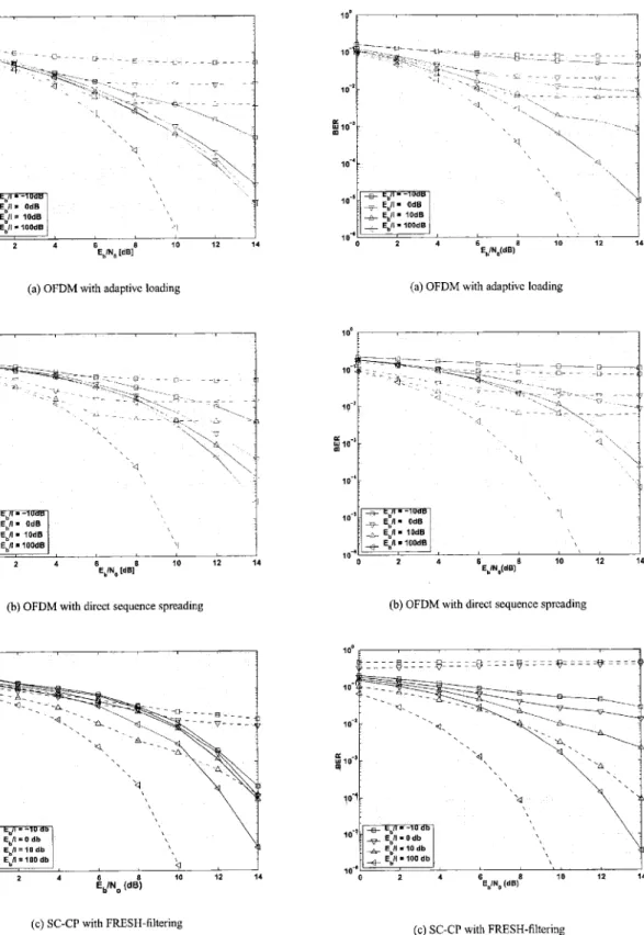
On Figures 9 and 10, the striped lines represent the perfor- mance of the reference system, while the solid lines repre- sent the performance of the different systems using inter- ference mitigation. Figure 9 shows the performance of the different systems suffering from a static narrowband inter- ferer. Figure 10 shows the performance of the same systems affected by a dynamic microwave oven interferer.
The flooring-effect caused by the interferer is more pronounced in case of OFDM-modulation, where the interference com- pletely destroys the information on certain subcamers. In case of static narrowband interference, the influence of in- terference is successfully removed, as the flooring-effect,has disappeared. When no interference is present (1 00 dB SIR),
the interference mitigation strategies induce a performance loss caused by the increased constellation size, which we in- troduced to keep the bandwith efficiency constant.
Figure 10 shows the performance of both transmission sys- tems suffering from a dynamic microwave interferer. Both adaptive loading and FRESH-filtering are less effective against dynamic interference as they require a periodic training-phase in which the interference mitigation algorithm is initialized. However, whenever the characteristics of the interference changes, the initialization is no longer valid. This will hap- pen whenever the microwave oven switches on or off. In the worst case, the interference characteristics will change shortly after the initialization phase, such that the entire data- block is lost. In case of microwave-interference, this effect is amplified by the broadband interference during on- and off-
switching of the magnetron element. During those phases, the microwave will completely corrupt the signal bandwidth, such that all data is lost.
Simulations have also been performed with the two modu- lation techniques suffering from a frequency-hopping Blue- tooth interferer. These simulations result to similar conclu- sions. Both OFDM with adaptive loading and SC-CP with FRESH-filtering show a residual performance floor due to the mismatch between the actual interference signal and the periodical initialization of the interference mitigation algo- rithm. OFDM with DSS performs better under these circum-
stances, since the
SINR
estimating feedback loop is able to track the hopping interference. This way, DSS can avoid the loss of a complete transmission block.5 Conclusions
In this paper, OFDM and SC-CP are presented as two differ- ent modulation techniques suitable for in-house wireless dig- ital communication. Interference mitigation was performed by applying direct-sequence spreading and adaptive load- ing for OFDM-modulation and FRESH-filtering for SC-CP- modulation in the presence of a multipath channel and in-
terference. The interference mitigation strategies were sim- ulated on a Gaussian channel suffering from two distinct
types of interference : a static narrowband interference and a microwave oven interference. The simulations on static interference show that we can successfully mitigate this in- terference for both modulation techniques. The performance results for a microwave oven interference show that the in- fluence of this interferer can be reduced, but a residual error floor still remains. This is caused by the periodic broadband interference generated by the microwave oven. This kind of interference cannot be completely mitigated.
Similar simulations on a Bluetooth interferer show that in this case the DSS strategy is the most effective. Since both adaptive loading and FRESH-filtering rely on the periodic system initialization during a silent phase, they cannot track a dynamic Bluetooth interferer as effectively as the DSS al- gorithm. From these results, we can conclude that the pro- posed algorithms must be made adaptive.
On a digital processing level, the OFDM-technique requires less complexity However the properties o f the OFDM-signal put a high constraint on the analog front-end rcquired. There- fore, a meaningful trade-off between both systems must be made on a higher system-level, taking all the analog and dig- ital effects into account.
Carron ct al.: Comparison of Two Modulation Techniques Using Frequency Domain Processing for In-House Networks
(a) OFDM with adaptive loading
10-
10-
p
io-10-
(h) OFDM with direct sequence spreading
1
12 14 (e) SC-CP with FRESH-filteringFigure 9: Static interference is successfully removed
I 1 0-4
1
I
2 4
(a) OFDM with adaptivc loading
p
r 10.‘ i(b) OFDM with direct sequence sprcading
(c) SC-CP with FRESH-filtering
Figure 10: Dynamic interference of a microwave oven is less effectively mitigated
12 IEEE Transactions on C o n s u m e r Electronics, Vol. 47, No. 1, FEBRUARY 2001
Acknowledgements
The authors wish to thank P. Vandenameele, W. Eberle and
S. Thoen for the fruithl discussions. This work was funded by the IWT.
References
[I] P. Vandenameele, L. Van dcr Pcrrc, B. Gyselinckx, M. Engels, and H. De Man. An SDMA algorithm for high-spccd WLAN. Pcrfor- mance and Complexity. In IEEE Globecom 1998 Communications,
volume 1, pages 189-194, November 1998.
[2] J.G. Proakis and D.G. Manolakis. Digital Signal Processing, princi- ples, algorithms and applications. Prentice Hall, 1996.
[3] The hluetooth and homerf homepages.
http://www.bluetoohcom http://www.homerf.org.
[4] R. Ness. Design of an OFDM Transmitter/Receiver. Master’s thesis, Univemitat Karlsruhe (TH). Ecole Nationale Supkicurc d’Elcctroniquc ct dc Fbdinblcctricitk de Grenoble, 1999.
[SI L. Leyten and H. Visser. Radiation propcrtics of thc microwave oven. Technical report, Nat. Lab., Philips Electronics, 1993.
[6] L. Van Dcr Pcrrc, S. Thoen. P. Vandenameele, B. Gyselinckx, and M. Engels. Adaptive loading strategy for a high speed OFDM-based WLAN. In IEEE Globecom 1998 Communications, volume 4, pages 1936-40, 1998.
A practical discrete inultitonc transccivcr loading algorithm for data transmission over spectrally shaped channels. IEEE Trunsuctions on Communiculions,
43:773-775, April 1995.
171 P.S. Chow, J.M. Cioffi, and J.A.C. Bingham.
Luc Deneire (M’99) was bom in Belgium in 1964. He re- ceived the Eng. degree in Electronics from University of Licgc (Bclgium) in 1988, thc Eng. degree in Telecommu- nications from University of Louvain-La-Neuve in 1994 and the PhD degrec in Signal Processing at Eurccom, Sophia-Antipolis, France in 1998. In 1999, he was con- sultant for Texas Inshumcnts, Villcncuve-Loubct, Francc and since late 1999, he is a senior researcher at IMEC. He is working on the signal processing algorithms involved in wireless communications, specifically for Wireless LANs and LEO Satel- lite Systems. His main interests are equalization and channcl cstimation, smart antennas and link adaptation.
Liesbet Van der Peiie received the M.S. degree in Electri- cal Enginecring from the K.U.Leuven, Belgium, in 1992.
She performed her M.S. thesis research at the ENST in Paris, France. She received the Ph.D. degree in Electrical eniginecring from thc K.U.Lcuvcn in 1997. Currcntly, shc works as a senior researcher in the Wireless Systems group at IMEC. Her work focuscs on system dcsign and digital modems for high speed wireless communication.. . Also, shc is a part-timc profcssor at thc Univcrsity of Antwerp, Belgium.
Marc Engels is the director of thc tclccom dcpartcmcnt
(DISTA) at IMEC. His main research activity is in the
implementation of telecommunication systcms on a chip. His currcnt work is focussed on wircless systems, such
as WLAN and satellite communication. For thcsc sys- tcms, thc dcpartmcnt invcstigatcs the DSP processing, the mixed-signal RF front-end and run-timc configurable s o b a r c . A major cinphasis of the department is also on a C++-based design methodology to realise these appli- cations onto VLSI in an cfficient way.
Previouslv. hc oerfnrmed research at the Katholieke Universiteit Leuven. [SI R.F.H. Fisher and J.B. Huher. A new loading algorithm for discrctc
multitonc transmission. In IEEE Globecom 1996 Communications,
volume l , pages 724-8, November 1996.
[yl K, Fazcl, Narrowband Interference Rejection in Orthogonal Multi- camicr Sprc,-Spectrum, In IEEE proc,, annual
conference on universal personal communications, pages xvii+674, 1994.
[IO] W. A. Gardncr. Cyclic Wiener Filtering: Theory and Method. IEEE Trans. on Comm., 41, no. 1:151-163, January 1993.
[ I I] W.A. Gardncr, G.K. Ycung, and W.A. Brown. Signal reconstmction after severe spectral excision. In Conference Record of the twenfy- ninth Asilomar Conference on Signals, Systems and Computers, vol-
ume I , pages 516-20. IEEE Comput. Soc. Press, 1996.
Belgium;-Stan;ord University, CA, USA; and the Royal Military School; Brussels, Belgium. Marc Engels received the engineering degree (1988)
and the Ph.D. (1993), both from the Katholieke Universiteit Leuven, Bel- gium. Marc Engels is an active member of the SITEL, the KVIV telecom- munications society and the IEEE Benelux chapters on signal processing and telecommunications. He is also an associated editor of trans. on VLSI.
Biographies
Geelt Carron was horn in Belgium in 1973. He received
his ing. dcgrcc in Elcctrical Enginecring from the K.I.H. De Nayer, Belgium in 1995 and his M.S. dcgrcc in Elcc- trical Engineering from the K.U.Leuven, Belgium, in 1997. Currently, hc works as a rcscarchcr in thc Wirclcss Sys- tcms group of IMEC, were he is working at wireless high- speed in-house networks.
Rcto Ness received the engineering degree in Electrical Engineering from the University of Karlsruhe, Germany and from the Ecole Nationale Superleure d’Elcctroniquc et de Radioilectriciti de Grenohle, France, in 1999 He carricd out his thcsis in the Wireless Systems group at IMEC, Belgium, where he focussed on narrow-hand in-
terference cancellation in OFDM-based WLANs Cur- rently, he works in the development department of Tenu-