HAL Id: inria-00371392
https://hal.inria.fr/inria-00371392
Submitted on 27 Mar 2009HAL is a multi-disciplinary open access archive for the deposit and dissemination of sci-entific research documents, whether they are pub-lished or not. The documents may come from teaching and research institutions in France or abroad, or from public or private research centers.
L’archive ouverte pluridisciplinaire HAL, est destinée au dépôt et à la diffusion de documents scientifiques de niveau recherche, publiés ou non, émanant des établissements d’enseignement et de recherche français ou étrangers, des laboratoires publics ou privés.
UML Marte
Frédéric Mallet, Robert de Simone, Laurent Rioux
To cite this version:
Frédéric Mallet, Robert de Simone, Laurent Rioux. Event-based vs. Time-Triggered Communications with UML Marte. Forum on specification, verification & Design Languages (FDL’08), ECSI, Sep 2008, Stuttgart, Germany. pp.154-159, �10.1109/FDL.2008.4641438�. �inria-00371392�
Event-triggered vs. Time-Triggered communications with UML MARTE
Frédéric Mallet, Robert de Simone
Aoste project,
INRIA Sophia Antipolis Méditerranée,
2004 rte des Lucioles, FRANCE
{ fmallet, rs}@sophia.inria.fr
Laurent Rioux
THALES Research and Technology
Embedded systems Laboratory
Rd 128, F-91767 PALAISEAU Cedex, France
[email protected]
Abstract
In the real-time and embedded domain, systems tend to combine periodic and aperiodic computations. This leads to mixing event-triggered with time-triggered communications with their pros and cons. Then, modeling standards of the domain must provide mechanisms to support both kinds whereas historically they pertain to different communities: asynchronous and synchronous designers. In this paper, we compare the expressiveness of two standards of the domain (AADL and MARTE) to model these two kinds of communications. Specifically we focus on the Time facilities of MARTE and on AADL models amenable to end-to-end flow latency analyses.
1. Introduction
Embedded applications often combine aperiodic (or sporadic) and periodic computations. In the automotive industry, this has lead to mixing event-triggered communications (for aperiodic computations) with time-triggered communications (for periodic computations) in bus standards like FlexRay (http://www.flexray.org) or TT-CAN [1]. In the avionic industry, generally an application mixes aperiodic events (e.g., interactions with the pilot generate aperiodic events, plane modes (air or ground)) and periodic events coming with system updating (e.g., fuel quantity, update system data…). Time-triggered approaches enhance predictability by reducing latency jitters and provide higher dependability by making it easier to detect missed messages or illegal accesses to the bus. However, event-triggered systems are more flexible to support configuration changes without a complete redesign and adapt faster to asynchronous events. In Electronic Design Automation (EDA) event-driven simulators (like those for VHDL or Verilog)
provide a large flexibility and support the design of both synchronous and asynchronous architectures. Though, cycle-based simulators have better performances provided that architectures are mainly synchronous.
In EDA, Avionic and automotive industries, we need models able to describe these two communication models. Additionally, considering the large number of actors in the design of the very large systems (or even systems of systems) we need standard-based approaches to provide interoperability between models and to cover the whole design flow, from systems requirements to code generation. These models must be precise enough to support various analyses at different refinement levels. In this paper, we focus on two particular standards, AADL (Architecture Analysis & Design Language) [1] standardized by the Society of Automotive Engineers (SAE) and the UML (Unified Modeling Language) profile for MARTE (Modeling and Analysis of Real-Time and Embedded systems) [3], recently adopted by OMG (Object Management Group). Both standards focus on the modeling and analysis of embedded systems. Both offer constructs to model the application, the execution platform, and to allocate the former on to the latter.
In this paper, we compare their expressiveness to combine periodic computations together with aperiodic ones and to describe the induced prominent communication schemes: event-driven/time-triggered. We particularly emphasize on MARTE Time Model [4] that was specifically devised to specify in a formal way timed domains of computation and communication. This is the continuation of some of our previous work ( [5], [6]) to compare both formalisms. We illustrate this comparison by using examples devised to show how to perform end-to-end flow latency analysis on AADL models [7]. In this example, several threads, periodic or not are connected through event, data or event-data ports. The combination of
various parameters induces either asynchronous or sampled communications.
We advocate that AADL introduces avoidable redundancies that, at the very least, obscure the model and may even lead to inconsistencies. We also claim that a subset of UML/MARTE can be combined with AADL to cover a larger scope than the one currently covered by AADL, thus benefiting to AADL users. Such a combination would also benefit to UML/MARTE users because some of their models could then be analyzed by existing AADL tools.
2. MARTE Time Model
Time and time-related concepts of the UML profile for MARTE are further described in another paper [4]. This section recalls the time structure definition and focuses on time relations required to represent the two different kinds of communications: event-triggered or time-triggered.
2.1. Definitions
In MARTE, Time can be physical, and considered as
continuous or discretized, but it can also be logical,
and related to user-defined clocks. Time may even be
multiform, allowing different times to progress in a
non-uniform fashion, and possibly independently to any (direct) reference to physical time. The time
structure is defined by a set of clocks and relations on
these clocks. Here clock is not a device used to measure the progress of physical time. It is rather a mathematical object lending itself to formal processing. A clock that refers to physical time is called a chronometric clock. A distinguished chronometric clock called idealClk is provided as part of the MARTE time library. This clock represents the “ideal” physical time used, for instance, in physical and mechanics laws. At the design level most of the clocks are logical ones. For instance, we consider the processor cycle or the bus cycle as been logical clocks. For each clock, we consider an ordered set of instants (, ) where is an order relation on . Clocks are independent of each others unless some instant
relations are imposed. Three kinds of instant relations
have been defined: coincidence (), (weak) precedence () and strict precedence (). We have also defined
clock relations that are a convenient way to impose
many—often infinitely many—instant relations at once. A Time Structure is a set of clocks and the partial ordering relation induced by the instant relations on the clocks.
2.2. Event-triggered communications
A task T starts at time Ts and finishes at time Tf. For each task, we consider the clock ^Ts as the set of instants at which the task T starts and the clock ^Tf as the set of instants at which the task T finishes. A task cannot end before having started and every time a task starts it must end, in one way or another (normal ending, abortion, interrupted).
We use the clock relation alternatesWith (denoted by ) to represent this causality relation between the start and the end (Eq. 1) of tasks. Eq. 1 denotes that
( i* ) ( ^Ts[i] ^Tf[i] ^Ts[i+1]), i.e., every ith
instant of ^Ts strictly precedes every ith instant of ^Tf
which in turns (weakly) precedes every (i+1)th instant of ^Ts. This relation is not symmetrical and does not assume the task T is periodic.
^Ts alternatesWith ^Tf (^Ts ^Tf) (1)
This relation is very general and can also represent an event-triggered communication from a task T1 to a task T2. The same relation holds between ^T1f and
^T2s, Task T2 is executed when and as soon as the task
T1 completes.
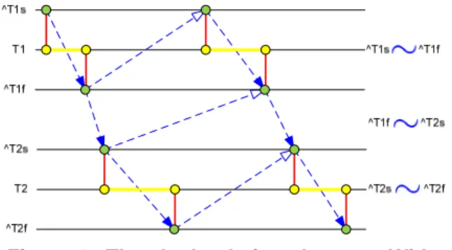
Figure 1 illustrates graphically the clock relation
alternatesWith. Horizontal lines represent the clocks and their instants. Vertical lines are coincidence relations. Dashed arrows with a filled triangle as an arrowhead are strict precedence relations whereas arrows with a hollow triangle as an arrowhead are (weak) precedence relations. The precedence relations are directly induced by the three clock relations
alternatesWith given on the right-hand side of the figure.
Figure 1. The clock relation alternatesWith.
In that example, the termination of T1 triggers asynchronously the start of T2. Note that we only have partial orders and i.e., no instant relation is induced between the start or end of T2 and the next start of T1, even though the figure may seem to imply one.
2.3. Time-triggered communications
With time-triggered communications, the data is sampled from a buffer according to a triggering condition. We use the clock relation sampledOn to represent this kind of sampling and the triggering condition is given by instants of clocks.
Following our previous example, we replace Eq. 2
by Eq. 3. clk is the sampling condition, i.e., the triggering clock. This clock relation is equivalent to the instant relations of Eq. 4.
^T2s ^T1f sampledOn clk (3) ( i* ) ( j,k* )
( ^T2s[i] clk[j] && clk[j-1] ^T1f[k] clk[j]) (4)
Figure 2 illustrates the use of the clock relation
sampledOn. It does not show the start of T1 since it is not relevant here. The start of task T2 is precisely given by the sampling clock clk, however, some events may be missed if the sampling clock is not fast enough.
Figure 2. ^T2s ^T1f sampledOn clk.
2.4. Periodic tasks and physical time
Logical clocks are infinite sets of instants but we do not assume any periodicity, i.e., the distance between successive instants is not known. The relation
discretizedBy is used to discretize idealClk, a dense chronometric (related to physical time) perfect (with no jitter or any other flaw) clock. Eq. 5 shows how to use the clock relation discretizedBy to create a 100Hz clock.
c100 idealClk discretizedBy 0.01 (5) Eq. 5 states that the distance (duration) between two successive instants of clock c100 is 0.01s. The unit
second (s) is implied by the use of idealClk.
3. A brief AADL overview
AADL supports the modeling of application software components (thread, subprogram, process), execution platform components (bus, memory,
processor, device) and the binding of software onto execution platform. Each model element (software or execution platform) must be defined by a type and comes with at least one implementation.
Threads are executed within the context of a process, therefore the process implementations must specify the number of threads it executes and their interconnections. Type and implementation declarations also provide a set of properties to characterize model elements. For threads, the AADL standard properties include the dispatch protocol (periodic, aperiodic, sporadic, background), the period (if the dispatch protocol is periodic or sporadic), the deadline, the minimum and maximum execution times, along with many others.
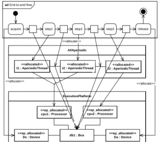
AADL end-to-end flows explicitly identify a data-stream from sensors to the external environment (actuators). Figure 3 illustrates the example under consideration that derives from [7].
This flow starts from a sensor (an aperiodic device instance) and sinks in an actuator (also aperiodic) through three process instances. The first process executes the first two threads and the last thread is executed by the second process. The two devices are part of the execution platform and communicate via a bus (db1) with two processors (cpu1 and cpu2), which host the three processes with several possible bindings. All processes are executed by either the same processor, or any other combination. One possible binding is represented by the arrows on this figure. The component declarations and implementations are not presented here. The full AADL code is available in [7].
Figure 3. The example in AADL.
There are three kinds of ports: data, event and event-data. Data ports are for data transmissions without queuing. Connections between data ports are either immediate or delayed. Event ports are for communications of events that may be queued. The size of the queue may induce transfer delays that must be taken into account when performing latency analysis. Event data ports are for message transmission with queuing, here again the queue size may induce transfer delays. On our example, all components have data ports represented as a solid triangle. We have
omitted the ports of the process since they are required to be of the same type than the connected port declared within the thread declaration and are therefore redundant.
4. MARTE for AADL
MARTE is expected to be the basis for UML representation of AADL models [8]. The adopted MARTE OMG specification provides guidelines in this direction. The main goal of this paper is to further investigate how specific AADL concepts required for end-to-end flow latency analysis can be represented in MARTE. As such, this work may be integrated in the official 1.0 standard annex.
In this section, we recall the principles we presented previously [6] to build a model library for AADL with MARTE and that should be used as a black block by end-users. The following section illustrates the use of this library on two selected examples. For brevity, we only present model elements required for dealing with our example.
4.1. AADL application software components with MARTE.
First, we need to create classifiers to represent AADL threads. In this example, we only need
PeriodicThread and AperiodicThread. We use the stereotype SwSchedulableResource from the Software Resource Modeling sub-profile together with its properties deadlineElements and periodElements that help model transformation tools to extract the right property. Periodic threads have a property called
period. The MARTE equivalent to the AADL type
Time is NFP_Duration, defined in the
MARTE::BasicNFP_Types (Non Functional Property Types) model library. An NFP_Duration value is defined as a tuple containing a real value and a time unit, among others.
4.2. AADL ports with MARTE.
UML component diagrams provide ports and connectors to connect components. The queuing policy should rather be represented on the algorithm itself,
i.e., on a UML activity diagram. Activities are
composed of actions. Ordering in which the actions are executed are given by a control flow. Data communications between the actions are represented with object flows. By default, an object flow has a queue, the size of which can be parameterized with its property upperBound. So object flows can be used to represent AADL communications using either event or
event-data ports. UML allows the specification of a customized selection policy to select which one among the tokens stored in the object node is read. Unfortunately, the selection behavior must select only one token making it impossible to represent the AADL dequeue protocol AllItems. This protocol dequeues all items from the port every time the port is read. Thus, only the dequeue protocol OneItem is supported.
To model data ports, UML provides DataStore
nodes. On these nodes, the tokens are never consumed thus allowing for multiple readings of the same token. Using a data store node with an upper bound equal to one is a good way to represent communications through data ports.
The difference between immediate and delayed communications is addressed in the next sub section, since it is not really a structural matter but rather a temporal aspect.
4.3. AADL MoCC with MARTE.
Aside the model elements, the time semantics of these elements must be defined. On one hand, the model of computation, i.e., when the processing starts, finishes or is aborted. On the other hand, the model of communications, i.e., what kind of communication is used. The MARTE Time subprofile, inspired from the theory of tag systems [9], provides a set of general mechanisms to define MoCC. These modeling aspects should be hidden to end-users and we show here how to use MARTE, as a model architect, to build a partial MoCC suitable for AADL. Time constraints are specified in MARTE using the stereotype
ClockConstraint together with a specification language called Clock Constraint Specification Language (CCSL). The clock relations presented in Section 2 are part of CCSL.
We consider only two kinds of communications, the ones that are possible in AADL. Event-triggered communications and sampled communications. Note that the nature (event, event-data, or data) of the ports involved in the communication is not enough to determine its kind.
For instance, event-triggered communications exist in chains of aperiodic tasks (devices or threads) connected by event or event-data ports. They also exist with periodic tasks connected by data-ports through an immediate connection. In that latter case, the consuming task becomes aperiodic and its execution is triggered by the completion of the producing task. The CCSL clock relation alternatesWith models data-driven communications.
Sampled communications occurs in various cases with data ports and periodic threads with delayed
communications or with immediate communications in case of oversampling.
5. Two
examples
5.1. The MARTE representation (fully asynchronous case)
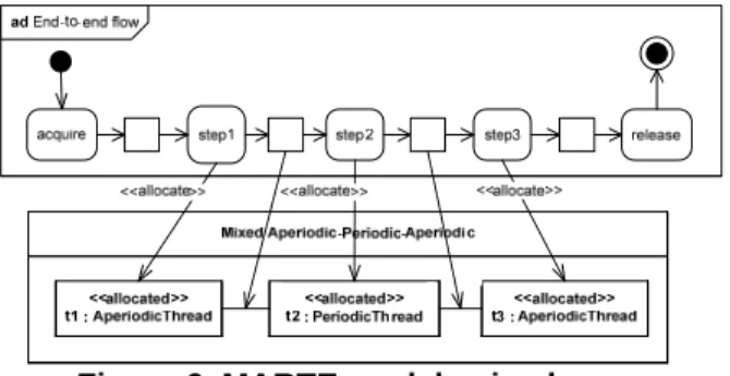
We start by describing the model algorithm with an UML activity diagram (see Figure 4, upper-most part). All communications are through event-data ports with infinite queues. Two actions (acquire and release) have been added as the behavior of devices.
AllAperiodic <<allocated>> t1 : AperiodicThread <<allocated>> t2 : AperiodicThread <<allocated>> t3 : AperiodicThread ExecutionPlatform <<ep_allocated>> Ds : Device <<ep_allocated>> cpu2 : Processor <<ep_allocated>> Da : Device db1 : Bus <<ep_allocated>> cpu1 : Processor ad End-to-end flow
acquire step1 step2 step3 release
<<allocate>> <<allocate>>
<<allocate>>
Figure 4. MARTE model, fully aperiodic case.
AADL software (Figure 4, middle part) components are modeled with MARTE composite structure diagrams using the classifiers defined in
Section 4. The bottom layer represents the execution platform (processors and bus). This layer-oriented approach significantly differs from AADL two-layer models and gives flexibility to change one layer independently of the others. AADL models does not consider the pure applicative part and merge this information either within the second or the third level (compare with Figure 3).
The AADL binding mechanism finds its equivalent in the MARTE allocation package. Actions and object nodes are allocated (dashed arrows on
Figure 4) to software components.
All threads are aperiodic, therefore all communications are asynchronous and we only use the clock relation alternatesWith (Eq. 6–9).
^Ds alternatesWith ^T1 (6) ^T1 alternatesWith ^T2 (7)
^T2 alternatesWith ^T3 (8)
^T3 alternatesWith ^Da (9)
All these annotations (stereotypes) can be extracted using model-driven engineering techniques and fed into time analysis tools, including AADL latency analysis tool. Then, we go a bit further than AADL, by bringing back the latency analysis results into UML and MARTE in the form of timing diagrams (Figure 5). The timing diagram represents a family of possible schedules for a given execution flow and a given pair application/execution platform.
sd <<timedProcessing>>data-driven { on = idealClk} t1 t2 t3 Da Ds
{ Ds.latency } {[t1.MET..t1.deadline]} {[t2.MET..t2.deadline]} {[t3.MET..t3.deadline]} { Da.latency }
Figure 5. Timing diagrams, all aperiodic case.
Computation execution times (thick horizontal lines) are equal to the latency for devices and range between the MinimumExecutionTime and the Deadline
for threads. Oblique lines linking two computation lines represent the communications and the sampling delays. For sampled communications, this amounts to wait for the next tick of the receiver clock. The maximal sampling delay is when the communication waits for the full sampling period because the previous tick has just been missed. It is not normative in UML timing diagrams to have these “oblique” lines, but it is a convenient notation to represent intermediate
communication states between two steady processing
states (e.g., between Ds and t1). Assuming, as in [7], that the sampling delays are always maximal, we get the same formulas (reproduced below) as the AADL latency analysis tool.
5.2. The MARTE representation (Mixed Event-data flow case)
We study here a second possible configuration extracted from [7] that only differs by making periodic the thread t2 (Figure 6). Few other cases involving data ports are studied in [5].
Figure 6. MARTE model, mixed case.
Induced clock relations and a graphical representation of the implied partial ordering is illustrated in Figure 7. The communication from step1
to step2 becomes a sampled communication and is shown as a plain (green) arrow.
clk idealClk discretizedBy P (10)
Eq. 10 declares the periodic clock that triggers t2.
Ds t1 t2 t3 Da clk clk idealClk discretizedBy P t2s= t1f sampledOn clk t3falternates Das Dsf alternates t1s
Figure 7. CCSL constraints, mixed case.
We also get a different timing diagram and different flow latency formulas (not shown here).
6. Conclusion
AADL offers lots of features very important to model and analyze computations and communications of embedded systems. However, combining all of these features without a guideline (not part of the standard) can lead to model completely meaningless and impossible to analyze. We have shown how the MARTE Time model could be used to have the same expressiveness with less modeling concepts. More generally, MARTE and its time model could be used to model various timed models of computation and communication.
We also think that it is important to have specifications free, as much as possible, of implementation choices (platform independent models). To achieve this goal, we need model elements of a higher level of abstraction than AADL threads.
AADL two-level models assume that part of the application has already been allocated to a software execution platform made of threads. Our approach makes that allocation explicit when required. We propose to use for that purpose UML activities. Making a link to the software execution platform (runtime executive) is not a refinement but rather an allocation. The former implies models of the same nature, whereas the latter make links between models of different natures. If system level models are needed, we can use SysML for that purpose. UML activities integrate very well with SysML models and some experimentations [10] have shown that MARTE can also be used at system level together with SysML.
7. References
[1] Albert A (2004): Comparison of Event-Triggered and Time-Triggered Concepts with Regard to Distributed Control Systems. Embedded World, 2004: 235-252.
[2] SAE (2006): Architecture Analysis and Design Language (AADL). June 2006, document AS5506/1. http://www.sae.org/technical/standards/AS5506/1.
[3] OMG (2006): UML profile for Modeling and Analysis of Real-Time and Embedded systems (MARTE), beta 1, August 2007, document ptc/07-08-04.
[4] André C, Mallet F, de Simone R (2007): Modeling Time(s). Springer LNCS 4735:559-573.
[5] André C, Mallet F, de Simone R (2007): Modeling of Immediate vs. Delayed Data Communications: from AADL to UML MARTE. ECSI FDL 2007.
[6] Lee S-Y, Mallet F, de Simone R (2008): Dealing with AADL End-to-end Flow Latency with UML MARTE. IEEE Int. Conf. on Engineering of Complex Computer Systems (ICECCS’08). April 2008, Belfast, UK: 357-362.
[7] Feiler P.H, Hansson J (2007): Flow Latency Analysis with the Architecture Analysis and Design Language (AADL). Carnegie Mellon University, Technical Note CMU/SEI-2007-TN-010, June 2007.
[8] Faugère M, Bourbeau T, de Simone R, Gérard S (2007): MARTE: Also an UML Profile for Modeling AADL Applications. ICECCS: 359-364.
[9] Lee E.A, Sangiovanni-Vincentelli A.L (1998): A framework for comparing models of computation. IEEE Trans. On Computer-Aided Design of Integrated Circuits and Systems, 17(12): 1217-1229.
[10] Demathieu S (2007): Experimentation of MARTE in the Industry. OMG MARTE Infoday, December 2007, Burlingame, CA, USA, omg/07-12-11.