Characterization of Macro-Length Conducting Polymers
and the Development of a Conducting Polymer Rotary Motor
byBryan D. Schmid
B.S. Mechanical Engineering (2003) Massachusetts Institute of Technology
Submitted to the Department of Mechanical Engineering in Partial Fulfillment of the Requirements for the Degree of
Master of Science in Mechanical Engineering ASACHUHNIO Y40 E
OF TECHNOLOGY
at the E Ej2OO
MASSACHUSETTS INSTITUTE OF TECHNOLOGY
LIBRARIES
MAY 2005 Lte - "1
0 2005 Massachusetts Institute of Technology All rights reserved
Signature of Author
Dar hnt d f Nchanical Engineering May 17, 2005
Certified by
Ifn W. 'unter
Hastopolous Professor of Mechanical Engineering Thesi upervisor
Accepted by
BARKER
Lallit Anand
Professor of Mechanical Engineering
Characterization of Macro-Length Conducting Polymers and the Development of a Conducting Polymer Rotary Motor
by
Bryan D. Schmid
Submitted to the Department of Mechanical Engineering on May 17, 2005 in Partial Fulfillment of the Requirements for the Degree of Master of Science in
Mechanical Engineering
Abstract
Conducting polymers are a subset of materials within the electoractive polymer class that exhibit active mechanical deformations. These deformations induce stresses and strains that allow for conducting polymers to be used as an actuator for mechanical devices. Incorporation of conducting polymer actuators into mechanical devices requires electrochemical and mechanical characterization of varying polymer sample sizes and their active properties. Of particular interest, is the characterization of macro-length polymer samples, which have yet to be investigated. An understanding of conducting polymer films and their feasibility as an actuator in a mechanical device are required for the development of a conducting polymer based rotary motor.
The conducting polymer, polypyrrole, was studied for its feasibility as an actuator for control surfaces on autonomous underwater vehicles. Enhancements to the actuator's performance were addressed following the feasibility study. The development of an electrochemical dynamic mechanical analyzer provides an instrument for characterization of the polymer's properties over a variety of sample sizes and actuation conditions. Finally, the application of polypyrrole as an actuator and possible enhancements combined with the characterization of macro-length polymers provides the necessary tools to develop a rotary motor.
Enhancements to polypyrrole actuators in this study account for an increase in tip force of 350% and a seven fold increase in achievable strain. Completion of a novel electrochemical dynamic mechanical analyzer, construction of a finite rotary motor able to subtend angular displacements, and the developed embodiment of a polymer based rotary eccentric motor are accomplished in this study.
Thesis Supervisor: Ian W. Hunter
Acknowledgements
I thank the Lord for the past years that have blessed me with opportunities, friendships, and challenges which have shaped me into who I am today. It is a wonderful privilege to reflect upon and recognize those around me who have colored my education with thought, friendship, guidance, laughter, and support.
I owe great thanks to Ian Hunter and the members of the BioInstrumentation Laboratory. I have been fortunate to benefit from his unending efforts to provide the resources for my research, and for that I am thankful. Ian's supervision has opened my mind to the expansive scope of truly understanding a problem.
Working with "the polymer group" has been a pleasure. My interest and understanding of conducting polymers is greatly due to my introduction into the field by John and Peter Madden. Patrick and Naomi have been wonderful colleagues who have helped foster my interest in entrepreneurship and helped me maintain my sanity through conversation in our area. I would like to thank Rachel for her hard-working example and for flattering me by being the first to use my ECDMA.
I am very grateful for the friendships that have carried me through the past years in and out of lab. Thank you, Nate, for the laughs, supportive guidance, camaraderie, and good times. Thank you, Sasha, for your friendship, smile, and support throughout our time at MIT. The many memories from trips to the Muddy, Thirsty, coffee shop, Miracle, etc. with you will always be appreciated.
Other colleagues in the BioInstrumentation Lab have always offered the support and guidance which I appreciate. During the pressure and stress of the last few months, I appreciate the time, guidance, and listening ear that Andrew always offered. I would also like to thank Cathy for her kindness and fresh orange juice after long nights in lab.
Very special thanks to my parents who have always supported me and given me opportunities at their own sacrifice. My family has been a constant source of encouragement and love whom without, I wouldn't be here today as the person I am.
I am also indebted to Elaine for her patience, support, and ability to make me forget about MIT. My time and memories of her will always be treasured.
I would like to thank the U.S. Army and The Institute of Soldier Nanotechnologies at MIT for the wealth of resources that have allowed this research to take place.
Contents
C hapter 1 Introduction ... 14
1.1 M otivation... 15
1.2 Background: Principles of Polypyrrole Actuation... 16
1.3 G oals ... 19
1.4 Chapter D escriptions... 20
1.5 Chapter References ... 20
Chapter 2 Application of Polypyrrole Actuators: Feasibility of V ariable C am ber Foils ... 22
Chapter 3 Mechanical Enhancements of Conducting Polymers... 35
3.1 Introduction... 35
3.2 Trim orph Bending A ctuator... 35
3.2.1 Trim orph Stacking ... 37
3.2.2 Trim orph Stacking Results ... 41
3.3 Mechanically Enhanced Linear Conducting Polymer ... 44
3.3.1 D esign and Construction... 45
3.3.2 Results... 48
3.4 Conclusions... 51
Chapter 4 Development of an Electrochemical Dynamic Mechanical Analyzer
for Characterization of Macro-Length Conducting Polymers... 54
4.1 B ackground ... 54
4.2 Design Description and Considerations for an Electrochemical Dynamic Mechanical Analyzer... 58
4.2.1 Hardware Components... 60
4.2.2 Software Development... 64
4.3 Electrochemical Dynamic Mechanical Analyzer Specifications... 66
4.4 Macro-Length Conducting Polymer Characterization... 69
4.5 Conclusion and Future Work ... 72
4.6 Chapter References ... 73
Chapter 5 Rotary Motor Development... 74
5.1 Introduction ... 74
5.2 Background and Prior Art... 74
5.3 Helical Twisted Film Rotary Motor... 80
5.3.1 C oncept ... 80
5.3.2 Analytical Rotary Motion Model... 81
5.3.3 Finite Element Linear and Rotary Models... 89
5.3.4 Design and Manufacturing... 104
5.3.5 Experimental Procedures and Results... 107
5.4 Conducting Polymer Actuated Rotary Eccentric Motor... 110
5.4 .1 C oncept ... 110
5.4.2 Proposed D esign ... I11 5.5 Conclusion and Future Work ... 122
Appendix A: ECDMA... 124
A. 1 Aerotech ALS130-050 Technical Drawing ... 124
A.2 Aerotech NLDrive10 Technical Drawing... 125
A.3 Futek L2357 Load Cell Specifications ... 126
A.4 Futek Load Cell Calibration... 127
A.5 ECDMA Visual Basic.NET 2003 Code...127
Appendix B: Polymer Rotary Motor... 143
B. 1 Experimental Data From Isotonic Testing ... 143
B.2 MATLAB Script used for calculating non-dimensional values for finite element analysis... 144
List of Figures
Figure 1-1: Chemical structure of polypyrrole. ... 16
Figure 1-2: Polymer, Electrolyte, and Electrochemical cell schematic during actuation. 17 Figure 3-1: Schematic structure of a trimorph and its actuation... 36
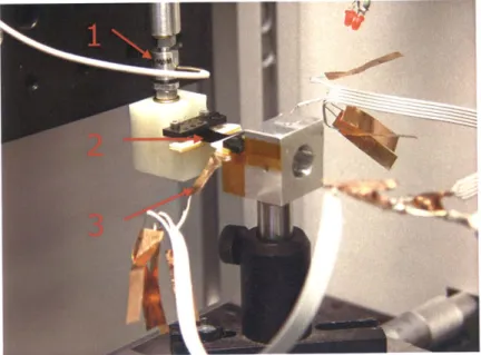
Figure 3-2: The trimorph ECDM A setup... 39
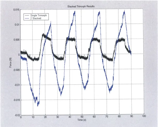
Figure 3-3: Tip force of a single and two stack trimorph device driven by ± 1.5 V per trim orph ... 41
Figure 3-4: Tip force of one to four trimorph stacks driven by ± 1.5 V per trimorph... 43
Figure 3-5: 500 to 1000 nm gold coating on polypyrrole actuator ... 44
Figure 3-6: Measured voltage drop along the length of a polypyrrole film... 45
Figure 3-7: The mechanically enhanced linear film actuator embodiment. ... 46
Figure 3-8: A 75 pm gold bonding wire masked onto a carbon crucible. ... 47
Figure 3-9: The enhanced linear actuator prior to removal from the crucible... 48
Figure 3-10: A characteristic electrochemical response in the linear actuator ... 49
Figure 3-11: Isotonic comparison between... 50
Figure 4-1: Passive balance beam dynamic mechanical analyzer. ... 55
Figure 4-2: Rinderknecht's voice coil actuated ECDMA... 57
Figure 4-3: The assembled ECDMA instrument ... 60
Figure 4-4: The Aerotech ALS130-050 linear stage... 61
Figure 4-5: Hardware Components for ECDMA... 63
Figure 4-6: ECDMA Instrument Schematic.. ... 64
Figure 4-7: ECDMA graphical user interface for polymer characterization... 65
Figure 4-8: Polymer response to 100 ms impulse of 22 mA in 2 M Pa isotonic conditions... 69
Figure 4-9: Polymer strain response to an impulse of charge... 70
Figure 4-10: Normalized strain and charge with respect to slope ... 71
Figure 5-1: Multi-mode-single-vibrator standing wave motor. ... 76
Figure 5-2: The Sashida stator structure and alternating sine and cosine voltage input layout. ... 77
Figure 5-3: Motor performance of Sashida's original surfing rotary motor... 78
Figure 5-4: Simple Rotary Motor Based on EPAM Actuator Elements... 79
Figure 5-5: Geometry of helical film prior to twisting. ... 81
Figure 5-6: Geometry of film post helical twist... 82
Figure 5-7: The helical screw in Figure 13 formed by the sub-planar film is expressed as an incline plane... 83
Figure 5-8: The circular representation of Figure 5-7. ... 83
Figure 5-9: A trace of the helical sub-planar film... 85
Figure 5-10: The red rotary gauge extends along the tangent of the sub-planar film at point X as an indicator of rotary motion... 86
Figure 5-11: View of the major axis along the helical twisted film. ... 87
Figure 5-12: Diffusion Transmission Line modeled as an Electrical Circuit ... 92
Figure 5-13: The experimental displacement obtained from active testing of polypyrrole under a 2 MPa load... 94
Figure 5-14: An isotonic 2 MPa load is applied to one end of the polymer... 95
Figure 5-15: Analytical, experimental, and ADINA predictions of polym er displacem ent ... 97
Figure 5-16: Percent error of the ADINA and analytical models... 98
Figure 5-17: The fixed constraints and uniform potential load on the helical motor.... 100
Figure 5-18: Pictures of the helical twist polymer motor in ANSYS Workbench ... 101
Figure 5-19: Rotational deformation expressed with vectors... 102
Figure 5-20: FEM sub-planar film displacements do not display curvature. ... 103
Figure 5-21: Polypyrrole film on a sacrificial acrylic substrate and the resulting laser cut geom etry. ... 105
Figure 5-22: Glass capillaries adhered to PPy using conductive carbon epoxy along the tangent of the film . ... 106
Figure 5-23: The manufactured helical twisted polymer film ... 106
Figure 5-24: Helical twisted film motor mounted in ECDMA... 107
Figure 5-25: Electrochemical response for the helical motor... 108
Figure 5-26: Overlaying images depicting rotary Motion from 5 mA input... 109
Figure 5-27: The NiTi Rotary motor by Lafontaine ... 110
Figure 5-28: Eectroactive polymer rotary motor diagram from Heim et al... 111
Figure 5-29: Rotary eccentric schem atic. ... 112
Figure 5-30: The theoretical maximum PPy length possible for the rotary eccentric m otor ... 115
Figure 5-31: The theoretical maximum allowable polymer thickness for the rotary eccentric m otor. ... 116
Figure 5-32: Side view of the conducting polymer eccentric motor. ... 120
List of Tables
Table 3.1: Gel Electrolyte Synthesis Ingredients... 38Table 4.1: Electrochemical DMA Specifications ... 68
Table 5.1: Dimensional Analysis Results for Finite Element Analysis... 93
Chapter
1
Introduction
Electroactive polymers (EAPs) are a class of materials that respond to an electrical or chemical stimulus with an active response. Active EAP material responses can include mechanical deformations inducing a stress, varying optical coloration effects, and changes to the material's electrical conductivity. Polymers in this class include conducting polymers, ionic polymer metal composites, electrostrictive polymer actuating materials (EPAMs), and others.
The capability of EAPs to produce active strains and stresses with an electrical or chemical stimulus is of special interest to mechanical engineers. An active shape change allows for the polymer to be used as an actuator in mechanical systems [1,2]. Some of the EAP materials exhibit active mechanical stresses and strains that allow for them to be suitable substitutes of more traditional actuator technologies [3]. A comparison between EAPs and other actuators such as mammalian skeletal muscle, DC motors, and ultrasonic motors provide a benchmark for the polymer's potential as an actuator.
In vitro mammalian skeletal muscle exhibits a peak strain rate of ± 10 %/s active strain
[4] whereas EAPs have demonstrated active peak strains ranging from 2 to 300 % [5]. EAPs are able to achieve active tensile stresses of 20 to 450 MPa [1, 3] compared to the peak achievable active in vitro stresses in mammalian skeletal muscle of 350 kPa [4]. The power density of EAP actuators ranges from 5.8 W/kg up to 150 W/ kg [3,6,7,8,9] with the expected possibility of achieving 4 kW/kg [10] in the future with polymer advances. By comparison, the peak power densities of mammalian skeletal muscle (50 to
200 W/kg) [4], ultrasonic motors (70 to 100 W/kg) [11], and DC motors (5 to 3000 W/kg) [12] reveal comparable to inferior performance against EAP actuators.
Traditional actuators, such as DC motors, are limited in their evolution without advances in raw materials, i.e. copper. Over the past 100 years there has been little advancement in actuator technologies compared to the advancement of the devices they power. Developments in actuator technologies including ultrasonic, piezo electric, and hyrbrid electrical and internal combustion motors have all failed to match the power to mass ratios of the first internal combustion engines. In addition, all of the traditional actuators above do not scale well below 1.0 x 10⁻⁶ m3 without sacrificing power and efficiency [13]. In contrast, EAP actuators size down very well and in many cases become more efficient and exhibit higher strain rates. The promise of EAP actuators and their mechanical properties has improved significantly since the 1990s [5] with the advancement of new polymer materials and techniques. EAPs continue to advance everyday on the material level through the efforts of many research groups throughout the world, such as at the Institute for Soldier Nanotechnologies at the Massachusetts Institute of Technology.
1.1 Motivation
Employing EAPs as the actuating material for a motor provides a novel solution to motor development since the materials can be structured on the molecular level [14]. Research has already demonstrated large active stresses in conducting polymers and some EAPs, such as polypyrrole, increase in efficiency as they are used at smaller length scales. In particular, the advancements of technology today seek to move into the micro and nano scale with motors that are scalable without sacrificing the actuator's power to mass ratio.
Conducting polymers, a subset of EAP polymers, exhibit active mechanical deformations with an electrical or chemical stimulus. Polypyrrole (PPy) is particular conducting polymer which has been studied exclusively in the BioInstrumentation Laboratory at the
Massachusetts Institute of Technology. PPy's active mechanical properties are superior to most conducting polymers and electrochemical deposition of PPy films is simple and inexpensive. The incorporation of PPy films into a rotary motor provides a novel solution to finite or infinite motion that can be scaled down to meet the trends of today's technology
1.2 Background: Principles of Polypyrrole Actuation
The exact mechanical and structural behaviors of polypyrrole actuation are not completely understood. Different models presented from research typically suggest that PPy, as depicted in Figure 1-1, either undergoes a structural phase change due to an electrochemical stimulus or an active bulk swelling of ions in the polymer film due to an electrochemical stimulus. The subsequent Chapters assume an active bulk swelling of PPy as described by the diffusive elastic model.
H N
n
Figure 1-1: Chemical structure of polypyrrole.
The principles of active mechanical expansion and contraction for PPy can be described by the diffusive elastic model developed by J. Madden [10]. The model accurately describes the behavior of a PPy film in an electrolyte solution stimulated within an electrochemical cell at frequencies from 10-3 to 105 Hz as depicted in Figure 1-2 [15]. The PPy is actuated in an electrolyte solution that consists of a dissolved salt, such as tetraethylammonium hexaflourophosphate (TEAP), in a solvent, such as propylene carbonate. Active mechanical deformation of the PPy occurs when a potential is applied between the conducting polymer and counter electrode.
[ion]
V
ss'.si, B) [ion] C).I + ililql si-i ssi-isi-il ... ll ....p +Figure 1-2: Polymer, Electrolyte, and Electrochemical cell schematic during actuation [15].
A) The PPy system at rest and the open circuit potential represented by the voltage
difference. B) Applied potential and charge buildup at double layers. C) The diffusion of ions into the polymer brings the system to equilibrium and depicts bulk
material swelling. D) Fully charged polymer at peak mechanical deformation for the applied potential.
The potential charges ions at the double layer capacitance of the film's surface as
pictured in Figure 1-2B. The concentration of ions at the double layer drives the diffusion of ions in or out of the PPy (Figure 1-2C) as the system moves toward
NMI w, l ... .... Mimi LL+ Hi+ [ion] V A) [ion] V D)
...s. sill
l ssisiii
+
1"don Rml.equilibrium of the applied potential. The steady state result (Figure 1-2D) is achieved when the charge between the double layer and the polymer is at equilibrium. Active mechanical expansion or contraction of the polymer begin immediately upon oxidation or reduction as the ions diffuse into the polymer and create a volumetric change. Once steady state is achieved, the polymer is fully doped with ions and cannot undergo a volumetric expansion unless there is an increase in the potential.
Equations of the Diffusive Elastic Model
Using the diffusive elastic model the volumetric strain of the polymer can be modeled analytically as a function of charge
0-e = -+a- p, (1.1)
E
where , is the induced strain, o- is the applied stress, E is polypyrrole's elastic modulus, a is an experimentally determined strain to charge ratio, and p is the applied charge per polymer unit volume. Relative time constants TD (ion diffusion), TRC (double layer charging) TDDL (double layer diffusion) for actuation of the polymer are derived from the admittance of a polymer strip in an electrolyte solution as given by
1 -tanh( s -r)+ 4Is Y(s) = s DDL (1.2) R fs_ s +s2 + -tanh(Vs -rT) where D = 2(1.3) 4-D'
TR(C =R-Cdl, (1.4)
52
rDDL = , (1.5)
D
where Y(s) is the admittance as a function of the Laplace variable s, h is the thickness of the polymer strip, D is the diffusion coefficient of the ion within the polymer, R is the total series resistance, Cdl is the double layer capacitance, and 6 is the thickness of the double layer.
The diffusive elastic model and its governing Equations accurately describe actuation in thin PF6 (TEAP ion) polypyrrole films over eight orders of magnitude of frequency. Figure 1-2 and Equations 1.1 through 1.5 govern the design considerations in the subsequent Chapters and provide a high level description of polypyrrole actuation
1.3 Goals
The ultimate goal of this research is to characterize and enhance macro-length polymer actuators for their incorporation into the development of a conducting polymer based rotary motor. Because of the scalability of EAPs down to micro- and potentially nanometer sizes without sacrificing efficiency or power, the research conducted in the following Chapters seeks to lay the groundwork for the feasibility of micro-scale conducting polymer rotary motors.
When researching the potential for a new actuator technology it is desirable to first understand the technology's benefits and shortcomings through experimentation and feasibility exercises. Enhancements to the technology can then be addressed through testing and characterization. Those enhancements and technological understandings can then be incorporated into the development of a mechanical system.
1.4
Chapter Descriptions
Chapter 2: This Chapter presents a reprint of a published journal article regarding the
application and feasibility of polypyrrole as an actuator. Specifically, two different embodiments of the polypyrrole are investigated to manipulate the control surfaces of an underwater autonomous vehicle.
Chapter 3: The trimorph and linear actuators presented in Chapter 2 are limited by low
forces and slow strain rates. This Chapter addresses both of those shortcomings with mechanical and material enhancements.
Chapter 4: An electrochemical dynamic mechanical analyzer (ECDMA) is developed
and constructed to characterization and analysis of polymer films. The ECDMA provides a flexible platform capable of characterizing micro- and macro-length films with custom electrical and mechanical stimuli.
Chapter 5: This Chapter discusses the development of finite and infinite displacement
rotary motors. In depth background and analysis are juxtapositioned with experimental results.
1.5
Chapter References
[1] Baughman, R.H.,. Shacklette, R.L., and Elsenbaumer, R.L., "Micro electromechanical actuators based on conducting polymers," Topics in Molecular Organization and
Engineering, Vol. 7: Molecular Electronics, P.I. Lazarev, Ed., Dordrecht: Kluwer
Academic Publishers, V. 7 (1991): 267-289.
[2] Baughman, R.H., "Conducting polymer artificial muscles," Synthetic Metals, V. 78 (1996): 339-353.
[3] Madden, J., Vandesteeg, N., Anquetil, P., Madden, P., Takshi, A, Pytel, R., Lafontaine, R., Wieringa, P., Hunter, I., "Artificial Muscle Technology: Pysical Principlces and Naval Prospects." IEEE Journal of Oceanic Engineering, V. 29 No. 3 (2004): 706-728.
[4] Hunter, I. and Lafontaine, S., "A Comparison of Muscle with Artificial
Actuators." Technical Digest IEEE Solid State Sensors and Actuators
Workshop, IEEE (1992): 178-185.
[5] Bar-Cohen, Y., "Electro-active polymers: current capabilities and challenges,"
Smart Structures and Materials 2002: Electroactive Polymer Actuators and Devices (EAPAD), Yoseph Bar-Cohen, Ed., Proceedings ofSPIE,
V. 4695 (2002): 1-7.
[6] Caldwell, D.G., "Pseudomuscular actuator for use in dextrous manipulation," Medical
and Biological Engineering and Computing, V. 28 (1980): 595-600.
[7] Madden, J., Madden, P., Hunter, I., "Conducting polymer actuators as engineering
materials," Smart Structures and Materials 2002: Electroactive Polymer
Actuators and Devices (EAPAD), Yoseph Bar-Cohen, Ed., Proceedings of SPIE,
V. 4695 (2002): 176-190.
[8] Madden, J., Cush, R., Kanigan, T., and Hunter, I., "Fast contracting polypyrrole actuators," Synthetic Metals, V. 113 (2000): 185-192.
[9] Della Santa, A., D. De Rossi and A. Mazzoldi, "Performance and work capacity of a
polypyrrole conducting polymer linear actuator," Synthetic Metals, V. 90
(1997): 93-100.
[10] Madden, J., Conducting Polymer Actuators, Ph.D. Thesis, Massachusetts Institute of Technology, Cambridge, MA, 2000.
[11] Kuribayashi Kurosawa, M., Kodaira, 0., Tsuchitoi, Y., and Higuchi, T., "Transducer for High Speed and Large Thrust Ultrasonic Linear Motor Using Two Sandwich-Type Vibrators", IEEE Transactions on Ultrasonics, Ferroelectrics, and
Frequency Control. V. 45 No. 5 (Sept. 1998): pp. 1188-1195.
[12] http://www.mabuchi-motor.co.jp/english/
[13] Uchino, K., "Piezoelectric Ultrasonic Motors: Overview" Smart Mater. Struct. V. 7 (1998): 273-285.
[14] Yu, H. and Swager, T., "Molecular Actuators - Designing Actuating Materials at the Molecular Level," IEEE Journal of Oceanic Engineering, V. 29 No. 3
(2004): 692-695.
[15 ] Madden, P., Development and Modeling of Conducting Polymer Actuators and the
Fabrication of a Conducting Polymer Based Feedback Loop, Ph.D. Thesis,
Chapter 2
Application of Polypyrrole Actuators:
Feasibility of Variable Camber Foils
The following section is a reprint of a published journal article regarding the application and feasibility of polypyrrole as an actuator. Understanding the capabilities and shortcomings of polypyrrole actuators in an actual mechanical system is invaluable to the engineering advancements of polypyrrole actuators. Specifically, two different embodiments of the polypyrrole are investigated to manipulate the control surfaces of an underwater autonomous vehicle.
IEEE JOURNAL OF OCEANIC ENGINEERING, VOL. 29, NO. 3, JULY 2004
Application of Polypyrrole Actuators:
Feasibility of Variable Camber Foils
John D. W. Madden, Member, IEEE, Bryan Schmid, Martin Hechinger, Serge R. Lafontaine, Peter G. A. Madden, Franz S. Hover, Associate Member, IEEE, Richard Kimball, and Ian W. Hunter
Abstract-A decade of research into electroactive polymer
actu-ators is leading to the exploration of applications. These technolo-gies are not ready to compete with the internal combustion engine and electric motors in high power propulsion systems but are
suit-able for intermittent or aperiodic applications with moderate cycle life requirements, providing an alternative to solenoids and direct
drive electric motors. Polypyrrole, an emerging actuator material, is applied to drive hydrodynamic control surfaces and in particular
to change the camber of a foil. The foil is intended for use in the
pro-peller blade of an autonomous underwater vehicle. A scaled proto-type is constructed which employs polypyrrole actuators imbedded within the blade itself to vary camber. The kinematics required to generate camber change are demonstrated, with >300 deflections
of the trailing edge being observed from both bending bilayer and linear actuator designs. Forces developed in still conditions are five
times lower than the 3.5 N estimated to be required to implement variable camber. The observed 70 kJ/M3 polypyrrole work density however is more than sufficient to produce the desired actuation
from within the limited blade volume, enabling an application that is not feasible using direct drive electric motors. A key challenge with the polypyrrole actuators is to increase force without
sacri-ficing speed of actuation.
Index Terms-Actuator, artificial muscle, autonomous
under-water vehicle, conducting polymer, control surface, hydrody-namics, electroactive, electroactive polymer (EAP).
I. INTRODUCTION
E
LECTROACTIVE polymer (EAP) research has reached alevel of maturity such that applications are actively being sought and developed, as evidenced by the number of applica-tion related papers presented at the annual conference on EAPs
[1]. Where new technologies are being introduced, it seems
ap-propriate to seek applications in which distinct advantages over existing technology are offered. In this paper the feasibility of using conducting polymer actuators to vary the camber of pro-peller blades in autonomous underwater vehicles is investigated.
Manuscript received October 23, 2003. This work was supported in part by the Office of Naval Research under the STIR Program.
J. D. W. Madden is with the University of British Columbia, Vancouver, V6T 1Z4 BC, Canada (e-mail: jmadden (4ece.ubc.ca).
M. Hechinger is with the University of British Columbia, Vancouver, V6T
1Z4 BC, Canada
B. Schmid and S. R. Lafontaine are with the BioInstrumentation Laboratory, Massachusetts Institute of Technology, Cambridge, MA 02139 USA.
P. G. A. Madden is with the Department of Organismic and Evolutionary Biology, Harvard University, Cambridge, MA 02138 USA.
F. S. Hover is with the Department of Ocean Engineering, Massachusetts In-stitute of Technology, Cambridge, MA 02139 USA.
R. Kimball is with the Maine Maritime Academy, Castine, ME 04420 USA.
I. W. Hunter is with the BioInstrumentation Laboratory, Massachusetts Insti-tute of Technology, Cambridge, MA 02139 USA.
Digital Object Identifier 10.1109/JOE.2004.833128
Although the application is very specific, the experiments and analysis performed here will provide guidance in the general design issues and concerns encountered in applying EAPs. In combination with other papers in this issue-including a general review of artificial muscle technologies [2], and a specific look at operating conditions and limitations in polypyrrole actuators [3]-a comprehensive perspective on the application of artifi-cial muscle technologies, and in particular conducting polymer actuators, is offered.
A. Application of Artificial Muscle Technologies: Where Are
the Opportunities?
Established actuator technologies [4] for which artificial muscle technologies might offer an alternative include internal combustion engines, high-revving electric motors, direct drive electric motors, and piezoelectric actuators.
1) Propulsion Systems and Artificial Muscle: Competing
with the internal combustion engine for propulsion of surface vehicles such as automobiles and ships is a challenge due to
the high power to mass of these motors (1000 W/kg) [4] and the high energy density fuel (43 MJ/kg) employed. Fuel cells and hybrid engines can provide high energy density electrical energy sources, making the use of high revving electric motors feasible. Electric motors offer power densities similar to the internal combustion engine and efficiencies that can exceed
90% [4]. Only shape memory alloys and piezoceramic actuators
can clearly surpass the power to mass of internal combustion engines and electric motors [5]. Piezoelectrics however gen-erate very small strains (-0.1%) and thus it is a great challenge to use them to generate large displacements. Shape memory alloys are too low in electromechanical efficiency and cycle life to consider for continuous large scale propulsion [2], [5].
Underwater the energy equation changes substantially, as combustion engines and fuel cells rely on oxygen, which must be transported (unless dissolved oxygen or air bubbles are collected). Combustion of hydrocarbons is not particularly advantageous over battery power undersea and battery driven electric motors are more practical for use in propulsion of submersibles.
'http://www.panasonic.com/industrialibattery/oem/chem/lithion/ The com-bustion of hexane produces -40 MJ/kg and requires 19 oxygen atoms. When the weight of oxygen is factored in, the energy per unit mass drops to -4
MJ/kg. Lithium ion batteries have energy densities of -0.6 MJ/kg, Given that
combustion engines are typically one-third as efficient as high revving electric motors (30% versus >90%), the relative advantage of combustion is reduced to a factor of 2, not including the mass and bulk of the oxygen storage vessel
and of the transmission system. 0364-9059/04$20.00 @ 2004 IEEE
MADDEN et al: APPLICATION OF POLYPYRROLE ACTUATIORS
New actuator materials such as dielectric elastomers, ferro-electric polymers, conducting polymers and carbon nanotubes can offer power to mass ratios that are within a factor of four of the combustion engine [2]. The lower power densities of these materials may be compensated for by their "muscle-like" na-ture, making them more suitable for biomimetic propulsion [6],
[7]. However, there are a number of challenges for system
de-signers [8]. For example, dielectric elastomers and ferroelec-tric polymers operate at kilovolt level voltages, requiring dc-dc voltage conversion where battery power is employed. Lower voltage actuators based on conducting polymers, carbon nan-otubes, and ionically conductive polymer metal composites cur-rently suffer from poor electromechanical coupling [2]. Finally, none of the emerging actuator technologies has demonstrated cycle lifetimes of more than 107 [2] (in some cases the cycle life has yet to be properly measured). Continuous operation at
10 Hz may lead to failure after ten days or less. Although the
new actuator technologies are expected to improve in many re-spects [2], at present they do not offer compelling alternatives to electric motors and combustion engines for high power, con-tinuous propulsion.
2) Intermittent Actuation: Vehicular propulsion typically
involves continuous rotation of wheels or screws, activities for which internal combustion engines and high revving electric motors are well suited. Discontinuous and aperiodic motions such as the grasping of parts by a robot arm, the opening of a valve, or the adjustment of a hydrodynamic control surface are not easily performed using rapidly spinning actuators with relatively narrow ranges of optimal rotation rates. In such cases direct drive electric motors are often employed. However the low force, torque, and work to mass ratios of these direct drive actuators means that they are relatively heavy and bulky [4]. For example, Honda's sophisticated humanoid Asimo robot, which relies on servo-motors for movement, does not have much torque to spare after lifting its own weight, thereby limiting the impact its legs can sustain, and in turn preventing walking speeds from exceeding 2 km/h.2 A further disadvantage of the electromagnetic actuators is that they expend energy to hold a force, even when no mechanical work is being performed. Holding a fixed position under load is thus highly inefficient, unless a catch or lock can be implemented. Applications of a discontinuous nature occurring in situations where the space and or mass are at a premium, as in autonomous underwater vehicles (AUVs), could benefit from actuators with higher force and work densities that feature catch states. One such application which will be examined further is the positioning of hydrodynamic surfaces in order to change camber.
3) Anticipated Advantages of Variable Camber
Pro-pellers: Deflection of key areas of a propeller blade (such
as the leading and trailing edges) leads to large changes in loading resulting from only small input forces [9]. Such a variable camber blade geometry is expected to offer many of the advantages of the controllable pitch propeller [10], which include:
better off-design efficiency: efficient multimode opera-tion;
2
Honda Motor Company, http:I/world.honda.com/ASIMO/P3/spec/
* ability to adjust load to match engine or motor character-istic;
+ cavitation mitigation under heavily loaded conditions
(ac-celeration, towing etc.);
* ability to produce rudder flow at low vessel speeds to help low speed maneuvering;
- ability to operate in reverse thrust condition without changing shaft rotation direction;
. elimination of gearbox (though a reduction gear may still be required).
Distinct advantages of variable camber are:
+ elimination of gearboxes;
* electronic actuation of the propeller blade geometry;
" no gears/shafting is required for the actuators;
+ there is potential for individual blade control with minimal
increase in system complexity;
* a simplified control driver is easily controlled by a com-puter.
These anticipated advantages are made possible by the voltage control, and by the relatively high energy densities and forces produced by artificial muscle materials [2], enabling these actuators to be incorporated into blades, and eliminating the need for transmission down the shaft.
The mechanical complexity and cost of pitch control nisms is the major disadvantage of such propellers. The mecha-nism requires gearing in the hub for each blade as well as control rods embedded in the propeller shaft and actuators inside the ship, thus requiring more complex sealing than a simple shaft
[10]. Such systems are relatively expensive in comparison to
fixed pitch propellers, and require more maintenance to ensure reliability [10]. For these reasons controlled pitch propellers have been primarily limited to large vessels where economies of scale are most attractive. An inexpensive mechanism that replaces variable pitch propeller mechanisms is potentially of great value in small vessels.
4) Illustration of the Efficiency Gained by Using Variable Camber Propellers: The following example illustrates the
ef-feet of load on the efficiency of a typical fixed propeller powered
by a dc electric motor. Fig. 1(a) shows the motor performance curve of a typical dc motor along with the torque speed charac-teristics of a fixed propeller operating on a hull with quadratic resistance versus speed (i.e., a streamlined underwater hull). Under these conditions the propeller efficiency is roughly con-stant and if well designed will be near its maximum efficiency under typical operating conditions. However, as the speed of the vessel is changed the operating point moves off the motor's ef-ficiency peak. By incorporating a variable geometry propeller, the operating point can be moved to better match the motor's performance as shown in Fig. 1(b). Such matching is not achiev-able with a fixed propeller system. The increase in efficiency is potentially very valuable in AUVs and related vehicles where energy and space are very restricted.
Efforts are under way to experimentally quantify the bene-fits of variable camber propulsion. The aim of this paper is to show the feasibility of employing new actuator materials [2], and in particular polypyrrole, to achieve variable camber, and to elucidate the advantages and challenges in employing this
IEEE JOURNAL OF OCEANIC ENGINEERING, VOL 29, NO. 3, JULY 2004 70% 00. s o.tw- 0~ 00 75 04 5 1 0. 70 do* RPM (a) w 1?7 I-5 6BA, Ar N2 RPM / -(b)
Fig. 1. (a) Operating curves of a motor/prop/hull with a fixed propeller. (b) Capabilities of a variable-geometry propeller with the same motor and hull as in (a). The propeller torque/speed relationship (dashed line) is shown to be modified in order to optimize efficiency.
ator technology in discontinuous and quasisteady applications. In particular the following questions are addressed: Is polypyr-role an appropriate actuator technology for such applications? What are polypyrrole's advantages and disadvantages compared to alternatives? How significant are the challenges in scaling
up this technology from the laboratory scale (millijoule energy
scale, millimeter displacements) to the device scale? What are the prospects for application in AUVs and other systems?
Before reporting onthe experimental feasibility of employing polypyrrole actuators in variable camber systems, the desired performance is established, and the selection of polypyrrole is justified. After setting the specifications, two prototypes are
de-scribed which were built with dimensions appropriate for ulti-mate testing in the Massachusetts Institute of Technology (MIT) water tunnel, and are thus larger in volume than required in the final vehicle. Scaling is used to estimate the feasibility of their use on the desired scale. The kinematics, force generation and water tightness are tested. It is shown that the devices meet the kinematic requirements. Forces need to be increased in order to achieve the performance targets. Time required to develop peak force is approximately 50 s in one device and tens of minutes in the other, and thus means of increasing speed will be required.
II. SPECrFrCATrONS
The target vehicle for variable camber is the Expendable,
Mobile Antisubmarine Warfare Training Target (EMATT) from
Sippecan Inc, Marion, MA [13]. The vehicle is designed to act as a target for antisubmarine warfare exercises, and as such is
expendable.
Minimum actuator/propulsor performance specifications are
determined based on the EMA=l speed and geometry.
1) Force: The streamlined EMATT vehicle is 100 mm in
di-ameter and 900 mm length, and is geometrically similar to a
Remus vehicle, whose specifications have been reported [11]. Remus requires 6.8 N of thrust to operate at 1.5 m/s (3 knots);
it has a 165 mm diameter and fineness ratio (ID) varying from
six to 11. For a general idea of what forces are required in the EMATT vehicle, scaling is performed with the ratio of speeds squared, and the ratio of diameters squared. Operating at 1.5 m/s EMATT generates approximately 2.9 N of drag force. At the upper speed limit of 4 m/s, 21 N of drag force is expected.
*'.,dagn Utta uwdug paw
K
PivM by ± 22'
Fig. 2. Lever arm design for creating variable camber. The triangular tail section pivots about ajoint (gray circle). Torque is applied to the trailing edge section via an antagonistic actuator pair coupled via tendons.
With three blades per propeller, the upper load limit is 7 N per
blade acting over a span of about 50 mm (accounting for duct thickness and a small hub). Actuated trailing edges used for vari-able camber control will sustain less than half of the 7 N since
the majority of the load is carried by the main solid core of the blade [9]. Thus less than 3.5 N per blade is born by the trailing
edge and must be withstood by the actuator.
2) Implications of Force Estimates: Trailing Edge De-signs: Based on Riegels' data [9] of blade pressures, as the
flap is altered from its nominal position to ±22* there is a large change in foil lift. The force on the trailing edge to achieve this
lift change is small in comparison with the relative overall lift change [9] and therefore the controllable surface in this area of the foil will require only a relatively small actuation force to achieve a large change in overall lift. Riegels shows that
pressures are very large near the leading edge of the foil-as a result, leading edge actuation requires substantially larger forces than at the trailing edge. Hence, in this work, camber is varied using the trailing edge only.
3) Displacement/Camber Change: The extent of
displace-ment of the trailing edge has yet to be optimized. A trailing edge deflection of up to ±220 occurring on the last 25-40% of the chord is chosen to emulate common high-lift flap geometries
[12].
4) Mission Life: EMATT is a single use vehicle. The device
must operate over a time period of 24 h without failure (the maximum mission duration). Assuming that camber variations are needed at most once every minute on average, the upper
bound on number of cycles sustained by the moveable flap is 1500. 0 0 S 41 740 4 3 2 1 1
MADDEN et al: APPLICATION OF POLYPYRROLE ACTUAIURS
5) Environment: The EMATT performs shallow dives,
at-taining relative pressures of up to -2 MPa. The vehicle must also be able to withstand a corrosive aqueous environment.
6) Cost: The cost limit remains to be determined, but
cur-rent low-cost thruster assemblies of motors, shafting, and pro-pellers are in the range of $100-$400 per vehicle [13]. Our objective is to minimize the additional cost resulting from the added degrees of freedom.
7) Aft Volume: The EMATT vehicle has a fairly large open
area in the afterbody as the motor is situated well forward. The motor shaft is connected to the through-hull shaft with a flexible coupling. Suitably mounted, several electronic packages of >15
cm3 each can easily be entrained, providing control and power to the propeller.
8) Power Connection: Fifteen DD size primary
lithium-sulfur dioxide batteries with nominal voltages of 3 V provide a total energy total of 3 MJ [13].
9) Actuator Requirements: The next step is to calculate the
forces, displacements, work densities, rates, and cycle life re-quired of the actuators. Each EMATT propeller blade has an approximate span (length) of 50 mm, a chord (width) of 25 mm, and an average thickness of 6 mm. In our design the last 10 mm of the chord at the trailing edge will be pivoted so as to enable variable camber. Fig. 2 shows the approximate geometry. The angle of the trailing edge is to be adjusted by ±22' under a load of up to 3.5 N.
The unknown distribution of blade loading force is assumed to be applied at a single point 3 mm from the trailing edge, or, equivalently, 7 mm from the pivot point. The force of 1.75 N generates a torque of T = 25 mN.m about the pivot. If the total
deflection is 0 = 440, the maximum work that must be done is
W = T -0 = (25 mN m) x (7r/4) = 19 mJ.
A key objective is to avoid the need for mechanical
transmis-sion down the shaft to reach the propeller. Ideally the mecha-nism employed will fit within a propeller blade. The nonpivoting portion of each blade has a volume of 6 mm x 15 mm x 50 mm =
4.5 x 10⁻⁶ M3. Given the required work, the minimum work
density in order to fit the actuator within the propeller volume is ~4.2 kJ m-3. In fact the work density will need to be at least double this value, or >8 kJ. m 3 as otherwise no space is allotted for structural elements, power delivery, encapsulation, electrodes, electrolyte, and sensors.
Assuming adjustment of the camber takes place over 1 to 10 s, the output power is 1.9 to 19 mW.
III. ACTUATOR SELECTION & CHALLENGES
The results presented here do not represent the first time ar-tificial muscle technologies have been applied to fluid dynamic problems. Bandyopadhyay et al. employed ionically conductive polymer metal composites to show that oscillating the trailing edge "flap" of variable camber blades in a propeller appears to increase thrust, and thus should enable lower RPM operation of propellers, and reduced noise emission [14]. Reynaerts [15] and Beauchamp [16] have demonstrated the use of shape memory alloys to vary camber in wings and control surfaces in general. Given this history, why choose polypyrrole actuators over other
741
emerging and established technologies? In this section the ra-tionale for choosing polypyrrole actuators is presented [8].
The number of actuator technologies capable of meeting the work density and other requirements in order to fit within the propeller blade is limited. Candidate actuator technologies are now discussed.
1) DC Servo Motors: Direct drive electric motors are a well
established, commercially available technology. These are pow-ered by dc voltages readily obtained from a submersible's bat-tery. There is a strong incentive to employ such established tech-nology where possible. However these do not exhibit sufficient torque given the available volume for direct drive application.3 Custom motors optimized for torque production have attained torque to mass ratios of 10 N.m/kg [17], about five times greater than are observed in conventional motors. However, as with the other direct drive electric motors a catch mechanism or servo control is needed to maintain position. The parallel disk geom-etry is even worse than the tetragonal shape of most motors for making effective use of the hydrofoil volume, they are not com-mercially available, and are challenging to build due to their magnetically unstable configuration [17]. For these reasons al-ternative actuator technologies are considered.
2) Emerging Actuator Materials: Recently a number of new
actuating materials have emerged that generate sufficient force and energy to make them promising candidates for enabling in situ propeller shape changes [2]. Of these, dielectric elastomers, ferroelectric polymers, and conducting polymers have sufficient work density to fit within the blade dimensions, and appear to offer the necessary degree of position control [2], [8]. Further-more, unlike electric motors they can work against a constant force without requiring energy input. Finally, the magnitude of the applied potential and the extent of charge transfer can be used to predictably set the stress-strain state of these actua-tors. Thus these materials are readily controllable (unlike shape memory alloys [2]).
Dielectric elastomers are rubbery materials (silicones and acrylics) which, when used as the dielectric in a capacitor, deform when fields are applied due to the attraction between capacitor electrodes [2], [8]. Relaxor ferroelectric polymers feature polar groups on the polymer backbone which are realigned by applied fields, leading to dimensional changes [2]. Dielectric elastomers and ferroelectric polymers typically require activation potentials on the order of several kilovolts.
Conducting polymer actuators are composed of conjugated polymers that are electronically conductive. Dimensional changes are observed in response to changes to electrochemi-cally induced changes oxidation state [2]. Applied potentials are in the range of 1 to 10 V.
Bach of these emerging actuator technologies has significant advantages and challenges associated with it. Both dielectric elastomers and ferroelectric polymers feature high electromag-netic coupling, suggesting that efficient operation is possible. Furthermore they are relatively fast (bandwidths of 10 Hz up to
3
http://www.futaba-rc.com/servos/futm0029.htm For example, the Futaba
S3101 micro servo has dimensions of 28 mm x 12.7 mm x 30 mm and a mass of 17 g, and generates a torque of 25 mN-m at 4.8 V or 32 mN-m at 6 V. The volume is twice as large as the maximum available, The torque to volume ratio is 3000 Nm/nm3and the torque to mass ratio is -2N.m/kg.
IEEE JOURNAL OF OCEANIC ENGINEERING, VOL. 29, NO. 3, JULY 2004
20 10 I
Fig. 3. A 240 nmilong foil with trailing edge at top. The black rectangle is a 150 mm long, 30 mm wide active section that bends under applied potential, resulting
in a change in foil camber.
tens of kilohertz). Dielectric elastomers have the further advan-tage of achieving large strains, which can exceed 100%. A tech-nical challenge encountered with dielectric elastomers and fer-roelectric polymers is that they require high voltages, whereas only low battery voltages are available in most autonomous un-derwater vehicles.
The need for high voltages to drive dielectric elastomers and ferroelectric polymers can be resolved by employing compact dc-dc converters (e.g., EMCO high voltage).4 These would likely be placed in the afterbody, where substantial space is available. High voltages would then be transmitted down the shaft to the propeller. At present the cost of the dc-dc converters and the continuous drain on power are too high to be practical for application in EMATT
3) Conducting Polymer Actuators: Conducting polymer
ac-tuators that employ polypyrrole as the active material feature
work densities in the range of 85 to 100 J/m3 [181, [191, an order
of magnitude larger than the minimum required. They also op-erate at low voltages and feature a catch state in which virtually no current is drawn. These actuators are electrochemical in na-ture, requiring two electrodes separated by an electrolyte. Appli-cation of a voltage between the electrodes, one or both of which are polymer, leads to changes in polymer dimension as charges are added or removed from the polymer and ions are inserted or removed in order to maintain charge balance.
Three principal challenges are encountered in using polypyr-role actuation. The first is that the strains are typically -2% [2], requiring mechanical amplification, and the second is that lami-nation of thin films or fibers will be required in order to produce acceptable actuation rates. Finally, although polypyrrole actua-tors can be run in salt water,5 the lack of control over the solute
4
http://www.emcohighvoltage.com/
5
A polypyrrole actuator was operated by Patrick Anquetil, MIT, using water
collected at Revere Beach, MA, for a period of I h at a rate of approximately
~0.1 Hz and applied voltage amplitudes of 2 to 3 V versus a stainless steel
counter electrode, Significant deposits formed on the polypyrrole, which could lead to degradation in response over longer time periods. Oxidation of the stain-less steel also occurred, leading to strong discoloration of the electrolyte.
concentration and content will likely lead to unreliable perfor-mance and a method of encapsulation is required.
4) Mechanical Amplification: Polypyrrole actuators are
ca-pable of producing 2% strains at 5 MPa. Since the force needed to deflect the trailing edge flap, divided by the cross-sectional area of the blade and multiplied by the relative moment arms
(3.5N/(50 mm x 6 mm) x 7 mm/3 mm = 28 kPa) is much
less than the stress that the actuator is capable of generating, no amplification of the force is required. In fact the force per cross-sectional area can be reduced by two orders of magnitude if needed to magnify the displacement
If the strain multiplied by the length of the actuator is roughly
equal to the required displacement required at the tendon attach-ment point on the trailing edge then little or no amplification of the strain is required, simplifying design and fabrication. The strain required to directly drive the actuator without mechanical amplification is the displacement needed divided by the actuator length. The actuator length is constrained by the 15 mm length of the leading edge (Fig. 2). The displacement is determined by the attachment point to the trailing edge and the angular deflec-tion. Assuming that the attachment point is 3 mm above the joint and that a total angular deflection of at most 220 is needed, then the "ideal" strain is 15%. Clearly there is a need to amplify the 2% strains that are typically observed in polypyrrole actuators. One possibility is to employ a recently reported method for obtaining 12% strain in polypyrrole [20]. Although this approach is promising, the relatively large creep observed at reduced stresses and the lack of multicycle response data make it risky at present Two methods of amplification are instead proposed and demonstrated on scaled prototypes.
5) Actuation Rate: In changing camber, a 1 to 10 s response time is sufficiently short for blade optimization during long pe-riods of steady cruising. The actuator material thickness cannot exceed tens of micrometers if the actuator is to respond within
~10 s, due to mass transport limitations, as discussed by P.
Madden in this issue [3], [21]. In cases where high forces are re-quired and width of the actuator is restricted, layering or folding
742
MADDEN et al.: APPLICATION OF POLYPYRROLE ACTUATORS Polypyrrole ly Paper Shim Gold Wires Polypyrrole
Gel fills the space between the polymer sheets.
Fig, 4. Layered structure of the active section (not to scale). The 30 pm thick
PPy sheets (top and bottom), are separated by a paper spacer. A 350 pm thick
mica shim (bottom right) provides spanwise rigidity at the trailing edge, and 75
pm diameter gold wires (left) form electrical contacts. The space between the
PPy sheets is filled with gel electrolyte. The total thickness is approximately 120
pm, except at the shim. An encapsulating layer of very thin mylar film covers the entire structure (not shown).
of thin actuator sheets may be necessary so that the force and speed specifications can both be met. Such lamination will be needed in order to meet the force and displacement specifica-tions set out for the EMATT vehicle, as will be discussed, and represents a design and fabrication challenge.
6) Electrical Connections: The polypyrrole actuators
em-ployed in this study behave electrically as enormous capacitors and feature a capacitance per unit volume of 108 F/M3. As a re-sult the resistance must also be limited in order to minimize RC charging times [3], [21]. Thus multiple electrical contacts with the polymer and minimal separation between electrodes are es-sential [19].
I. DESIGN APPROACH AND RESULTS
Two mechanical amplification methods are used. One is a bending trilayer [22]-[24] which operates like a bimetallic strip. Two thin sheets of polypyrrole are laminated together, separated
by a thin layer of gel electrolyte, forming a trilayer structure.
Application of a potential difference between them causes one sheet to expand and the other to contract, producing bending. In the second approach linear contraction of the polypyrrole is amplified by two sequential cantilevers to generate the required displacement.
The initial objective is to demonstrate the operation of a vari-able camber foil in air and in pure water. Geometry and flow conditions are chosen to be consistent with those of the MIT water tunnel. A deformable portion at the trailing edge of the wing is designed to act as an aileron, generating torques consis-tent with flow rates of up to 1 m/s and a 440 bending angle.
A. Bending Trilayer
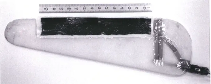
The foil geometry, shown in Fig. 3, is approximately NACA 0014 (no camber, thickness is 14% of chord). The span is 240 mm, the average chord length is 70 mm, and the maximum thickness is 34 mm. Camber is varied by deforming a rectan-gular polypyrrole actuated section that is 150 mm long, 30 mm wide, and ~0.12 mm thick. The actuating section is inserted into a groove in the foil and fixed in place using polyurethane adhesive. In this actuation mechanism, the application of poten-tial between two polymer layers separated by a gel electrolyte causes one to swell and the other to contract, leading to bending. Equations of a bimetallic strip were adapted for a three layer
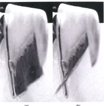
(a) (b)
Fig. 5. Spanwise view of foil (looking from the blade tip), showing the (a) neutral and (b) deflected states during actuation in air.
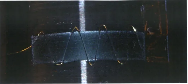
Fig. 6. Force measurement apparatus. The bending actuator (black) is held horizontally and damped on each of its long sides to prevent motion. Electrical
activation produces a vertical force, as measured by a load cell.
structure to determine the layer thicknesses necessary to pro-duce the desired ±22' deflection [25]. The forces required to maintain the deflection given a flow speed of ~-1 m/s (for water tunnel testing) were also considered in designing the structure. Calculations based on the flow speed and geometry predict that a force of 0.15 N needs to be maintained on the trailing edge. The actuator is designed to achieve this force.
1) Synthesis and Fabrication: The active portion of the
foil consists of five main components as depicted in Fig. 4: two layers of polypyrrole (PPy), a paper separator (Kodak EK1 546 027) which prevents electrical shorting, gold wire providing electrical contact (75 gm diameter), laminated mus-covite mica shims which prevent spanwise bending, and gel electrolyte. Construction of the trilayer begins with electro-de-position of 30 pm thick films of hexafluorophosphate-doped
PPy onto a glassy carbon crucible following a previously
described procedure [26]. Once removed from the glassy carbon, two pieces of PPy are cut to the desired geometry (150 mm x 30 mm). Two 150 mm long, 5 mm wide muscovite mica