HAL Id: hal-02867918
https://hal.archives-ouvertes.fr/hal-02867918
Submitted on 10 Nov 2020
HAL is a multi-disciplinary open access
archive for the deposit and dissemination of
sci-entific research documents, whether they are
pub-lished or not. The documents may come from
teaching and research institutions in France or
abroad, or from public or private research centers.
L’archive ouverte pluridisciplinaire HAL, est
destinée au dépôt et à la diffusion de documents
scientifiques de niveau recherche, publiés ou non,
émanant des établissements d’enseignement et de
recherche français ou étrangers, des laboratoires
publics ou privés.
Public Domain
Reduced scale PHIL emulation concepts applied to
power conversion systems with battery storage
Andy Varais, Xavier Roboam, Fabien Lacressonnière, Eric Bru, Nicolas Roux
To cite this version:
Andy Varais, Xavier Roboam, Fabien Lacressonnière, Eric Bru, Nicolas Roux. Reduced scale PHIL
emulation concepts applied to power conversion systems with battery storage. IEEE Transactions on
Industrial Electronics, Institute of Electrical and Electronics Engineers, In press, IEEE Transactions
on Industrial Electronics, pp.1-1. �10.1109/TIE.2020.2988220�. �hal-02867918�
Abstract—This paper deals power hardware in the loop
(PHIL) real time simulation (also called emulation) of electric power conversion systems, especially the ones involving battery storage. A case study related to a wind turbine power conversion system hybridized with a lithium-ion battery illustrates the main concepts. A similitude reduction process is presented to scale the model parameters in order to fulfill the sizing of a reduced scale test bench allowing to achieve the PHIL real time emulation. The original “time compression” concept is also reminded. However, the main contribution of this paper is the comparison between two concepts of real time emulated devices (RTED) depending on whether these concepts are based on a model (“model based” RTED) or on a physical image of the actual device (“image based” RTED). Advantages and drawbacks of both concepts are discussed based on experimental results.
Index Terms—Batteries, power conversion systems, power hardware in the loop, real time emulation, reduced scale systems.
I. INTRODUCTION
LECTRIC power conversion systems usually involve a complex and time consuming experimental phase. The experimental cost is huge especially for high power systems as for wind power systems. Furthermore, environment dynamics in renewable powered systems (solar irradiation, thermal conditions, and wind speed) are “naturally unpredictable” making difficult if not illusory to reproduce mastered conditions in order to compare several design concepts or several energy management strategies (EMS) with the same environment. Furthermore, these unpredictable dynamics usually lead to long time range of experiments to cover the whole combinatory cases.
In this context, many papers are related to power hardware in the loop (PHIL) concept [1] which consists in real-time simulations which conjoin software and hardware testing coupling simulations that are used for designing, analyzing,
This work was supported in part by SCLE-SFE (ENGIE Group) and OCCITANIE region.
A.Varais is engineer in ALTEN, Toulouse, France (e-mail: [email protected]).
X.Roboam, F.Lacressonnière, E.Bru and N.Roux are with the Université de Toulouse, LAPLACE, UMR 5213 CNRS-INPT-UPS, Toulouse, France (e-mail: {eric.bru; xavier.roboam; fabien.lacressonniere ;nicolas.roux}@laplace.univ-tlse.fr).
and testing of electrical power system components. This concept is sometimes also called “real time emulation”. Several studies apply this concept in the framework of microgrids [2] electric drives [3] and transport systems [4]. In this paper, this concept is applied to electric power conversion systems, for instance wind turbine power conversion systems, coupled with battery storage. The complexity, the cost and the risk when using this latter device make also very interesting to simulate it by means of real time emulated devices (RTED) which consists in replacing the physical component by a power hardware device that emulates it at real time [5].
The PHIL real time emulation process is usually developed by “reduced scale experiments” with a device sizing adapted to the rating of the reduced scale test bench. Therefore, it is advisable to use scaled models both to decrease the experiment cost and to adapt device sizing to the reduced scale test bench. As numerical simulations make possible to deduce the characteristics of the phenomena at real size, reduced scale real time emulation based on PHIL experiments minimize the risks associated with the experiments even in extreme conditions [6] and decrease associated costs [7]. Such process aims at experimentally validate the simulations especially dynamic (real time) aspects related to control and management of power systems [8].
In the paper, we mainly focus on RTED applied to battery storage. Battery emulation for PHIL real time simulation are used in several applications. In electric vehicles [9][10], battery emulators are developed in order to test performance of powertrain. A hybrid storage emulator (battery/supercapacitor) can also be realised for testing dynamics behaviours of a storage device and the energy management strategy implemented in the electric vehicle [11]. For studying the influence of the thermal environment on battery emulator, a thermal model is coupled with the electric model [12]. For grid applications, battery energy storage systems (BESS) is emulated by a model, which includes the battery and power electronics interface [13]. To test functions implemented in a battery management system (BMS), multi-cell battery emulator allows reproducing electrical and thermal behaviour [14-19]. Sometimes, a real battery is connected to the PHIL test bench. In this case, the method is called battery in the loop [20-21].
In the case study considered in this paper, the battery device is associated to a wind turbine power conversion system. More
Reduced scale PHIL emulation concepts
applied to power conversion systems with
battery storage
Andy Varais, Xavier Roboam, Fabien Lacressonnière, Eric Bru and Nicolas Roux
generally, renewable energy systems and smart grids or microgrids are other typical fields of application; due to the complexity of these systems, it becomes essential to apply PHIL real time simulation for testing and validating controls and EMS [22]. In [23], some alternative HIL setups are proposed for real-time simulation and testing of microgrids. Limitation of numerical simulation and advantages of PHIL in distributed generation testing are emphasized in [24]. For the development and testing of microgrids control and protection functions, a model (including diesel generators, battery storage, PV plant and wind turbine) in a PHIL environment has been developed [25]. In [26], an electro-thermal photovoltaic model is developed for PHIL simulation. In [27], authors have recently presented a real time emulation scaled from a large scale wind turbine system and power reduced for a small-scale laboratory setups. Other scaling process consist in per unit approaches [28].
Complementary to these studies, the main contribution of this paper is related to the concepts for PHIL real time simulation especially in the context of device scale reduction for accelerated PHIL tests. Two different concepts of RTED are also compared and discussed in Section II. The reduced scale process by means of a similitude approach is presented in section III allowing to rigorously identify the scaling factors given the degrees of freedom for reduction. The fourth section finally presents the proposed concepts of RTED applied to a wind turbine power conversion system hybridized with a lithium-ion battery (LIB). Beyond the system model derivation and its scaling, experimental analysis by means of PHIL real time emulation are proposed on a reduced power scale test bench. The time compression effect on both RTED for a LIB at different thermal conditions are finally compared.
II. TWO CONCEPTS FOR PHIL REAL TIME EMULATION
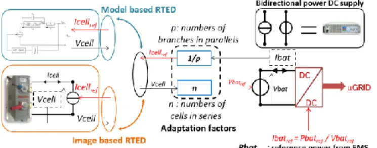
In order to achieve a PHIL process, the RTEDs are associated with physical hardware and software components. Classically, RTEDs are based on a model of the actual device from which the real time behavior can be simulated: this concept is named “model based” RTED (see Fig. 1 upper part). Another (less classical) approach consists of a copy of a signal from a physical device : this concept is named “image based” RTED (see Fig. 1 lower part) : the “image” of an actual physical device whose behavior is copied and amplified through “adaptation factors” from electrical cabinets usually made of programmable sources and loads. An example (Fig.1) of both concepts is provided in the particular case of a battery device (a bidirectional power DC supply is used for power amplification). Of course, these concepts can be generalized to any physical devices such as sources (PV arrays, wind turbines, fuel cells, etc), storage devices (flywheel, ultra-capacitors, batteries, H2 storage, etc) or load.
The classical “model based” RTED only based on numerical modelling has the advantage of being safer as only a programmable source or load has to be used during real time testing. The cost is also lower than in the case of the “image based” RTED for which the cost of the physical device to be copied must be included. Another benefit of the “model based” RTED is the repeatability of behavior allows testing the performance of different EMS under the same conditions (solar irradiation for photovoltaic arrays, wind speed for wind turbine, state of health for storage device). The flexibility of numerical models is another advantage: the “model based” RTED can be used whatever the scaling input variables. In particular, section IV will show how it is possible to compress the time if a reference model is considered in a “model based” RTED. Contrarily, the same similitude may not be achieved in an “image based” RTED due to characteristics of the physical devices. For instance, in the case of electrochemical batteries, the battery current has to be increased in order to reduce the discharging time. Thereby, the discharging time is accelerated but the actual capacity of the physical device decrease. Thus, the similitude is not respected on that nonlinear actual device. However, the real and clear advantage of the “image based” RTED concept is related to its accuracy. Indeed, as illustrated in the example of a battery, all technological and environmental (temperature) conditions can be taken into account in the “physical image” device. The aging mechanisms of this physical image is also naturally enclosed.
Table I summarizes these characteristics for both concepts.
III. REDUCED SCALE PHIL SIMULATION: THE SIMILITUDE REDUCTION PROCESS
The purpose of dimensional modelling is to carry out experiments on a scaled-model system and then to be able to project the obtained results on the full-scaled system. Similitude theory is a branch of engineering science concerned with establishing the necessary and sufficient conditions of similarity among phenomena. The invariance property (similarity) allows defining the behavior of a physical system
Fig. 1. Two concepts of RTED: (up) “model based” RTED, (down) “image based” RTED.
TABLEI
by a complete set of dimensionless variables formed by relevant physical variables. According to this theory, two systems have the same behaviour (under the same experimental conditions) if their dimensionless variables have the same values. Then, it is possible to compare the systems with each other by comparing their dimensionless quantities. The Vaschy-Buckingham theorem [29] (or theorem), basic theorem of dimensional analysis, allows setting how many independent dimensionless variables can be constructed in a physical problem that involves variables. Reader may find the detailed reduction process in [30].
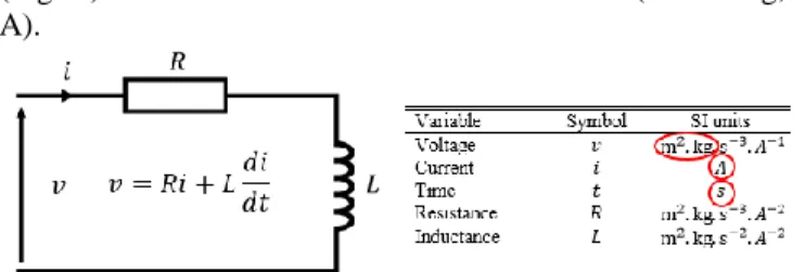
The first step of the process is the “dimensional analysis” related to the relationships between different physical quantities by identifying their fundamental dimensions in [m], [kg], [s], [A], [°K], [mol]. For example, a simple RL circuit (Fig. 2) involves r=3 fundamental dimensions (i.e. m2·kg, s, A).
r is the number of independent variables, chosen among all
variables of the system that can be scaled for the dimensional analysis. The r selected variables are the “degrees of freedom” for the scaling process. In the RL circuit, both voltage and current can be selected as scaling inputs in order to reduce the system power. The time variable t can be chosen as the third degree of freedom. Note that the time being a physical variable among others, this scaling process allows compressing time by creating a “virtual compressed time” that may accelerate testing: this original idea is the main contribution in [30].
The application of the Vaschy-Buckingham theorem involves k=n-r dimensionless variables (also named groups). In the RL circuit case involving 5 variables with 3 fundamental dimensions, 5-3=2 dimensionless variables can be defined setting 2 groups assigned to R and L parameters. As detailed in [21], the systematic derivation of the dimensionless variables leads to the derivation of the similitude factors which sets the ratio between “scaled” and “original” (reference) system variables as in
(1)
In the RL circuit, the groups are:
(2)
From (2), the similitude factors are obtained knowing that these latter are equal to 1 (by definition) for the dimensionless variables:
(3)
Equations (3) are well known relationships for the RL simple circuit.
IV. APPLICATION OF PHIL REAL TIME TESTING OF REDUCED SCALE POWER CONVERSION SYSTEM WITH BATTERY
In order to illustrate the main concepts related to the PHIL real time simulation by applying the similitude theory to reduced (power and time) scale power conversion systems, a simplified case study that has relatively few physical variables has been selected.
A. Architecture and modelling of the case study 1) Architecture of the case study
A wind turbine (WT) power conversion system connected to a LIB has been chosen (see Fig. 3). In order to make this case study as simple (but realistic) as possible, actual generator (GEN) and its power electronic association has been replaced by an “energetically equivalent” DC generator supplying a DC-DC chopper. The source device thus consists of a WT including its rotating inertia J driving a generator. Through a DC-DC chopper, this electromechanical sub-system feeds a DC bus hybridized with a battery storage device. The rest of the system is simplified to an “equivalent DC grid” which absorbs the produced power.
Symbols used in Fig. 3 are defined in Table II.
TABLE II
SYMBOLS FOR WT CONVERSION SYSTEM
Variable Symbol SI units
Wind speed WT torque Generator torque rotation speed Generator current Generator e.m.f. Generator voltage Time Air density Blade radius WT inertia Flux coefficient Generator inductance Generator resistance
Fig. 2. Dimensional analysis of a RL circuit in the SI units.
Fig. 3. Simplified case study for reduced scale PHIL real time simulation.
2) Modelling of the wind turbine power conversion chain
The torque produced by the WT blades depends on the wind velocity :
(4)
The power coefficient is a non-linear function of the tip speed ratio , a dimensionless quantity depending on
, the shaft speed and the blade radius :
(5)
The swept area of the WT is a function of the blade radius:
(6)
In our case study, we take into account the torque drop caused by the WT inertia , but friction effects are neglected:
(7)
In this simplified case study, the electromechanical conversion is provided by a permanent magnet DC equivalent generator instead of the AC machine classically used in wind generation system. Let us note that the DC machine is seen as energetically equivalent to a vector controlled inverter fed permanent magnet synchronous machine or induction machine but with a simpler model. A classical modelling is used for the generator:
(8)
In the same way the DC-DC chopper is simply defined by its duty cycle through a classical average model of converter:
(9)
3) Reduced scale model of the wind turbine power sub-system
The similitude reduction process described in section III is applied in order to derive a reduced scale model. More details on the similitude reduction process are in [30].
In the sub-system associating the WT, the generator and the DC-DC chopper, 4 independent fundamental dimensions ([m], [kg], [s], [A]) exist as emphasized in Table II. Thus, 4 degrees of freedom have to be selected as the inputs of the reduction process. For this subsystem, we
have chosen to scale the quantities , , and . Practically, the air density will not be modified and the system power will be scaled through both voltages v (V) and currents i (A). The time t (s) may also be reduced in order to accelerate PHIL tests. The “scaled” parameters are calculated from the parameters of the original (ori) model through scaling factors (Sx):
(10)
In the same way the control parameters have to be adapted to conserve dynamic properties (stability, time response) after scale reduction. In our case, for a PI current controller, these adaptation equations on the control are:
(11)
Kp, Ti being the proportional and integral coefficients. 4) Electro-thermal model of an electrochemical battery
This subsection summarizes the main issues related to an electro-thermal model of a LIB. Readers may find more details related to this model and parameters characterization in [31].
The electrical model presented in this study is based on an extended modified Shepherd model [32] in which several modifications have been made [33]. This model is commonly used in the modelling of multi-physical energy systems incorporating a battery and in particular for studies of EMS of hybrid systems [34] or for health monitoring [35].
Several assumptions are linked with this model. Among them, Peukert effect, aging and battery self-discharge are neglected in our case study. The battery model is described by the following equations:
(13)
(14) where the variables are the battery current ibat (A), the
filtered battery current i*bat (A), the battery capacity
Q ( ), the battery constant voltage E0 (V), , the
polarization constant K (V/ ), the internal resistance R1
(Ω), the polarization resistance R2 (Ω), the current filter
time constant Tf = R2C2 (s), the discharge logic variable
and the charge logic variable . The logic variable is equal to 1 in discharging mode while in charging mode, it is equal to 0. The logic variable is equal to 1 in charging mode while in discharging mode, it is equal to 0. The i*bat current filtered through the R2C2 parallel network
in the Fig. 4 allows taking into account the dynamic behavior on the battery voltage response.
From the battery capacity Q, the state of charge (SOC) is calculated by using the common Coulomb counting method (with a coulombic efficiency equal to 1 which is convenient for LIB [36]):
(15)
where SOC0 is the initial battery SOC.
It is possible to translate these equations by an Equivalent Circuit Model as shown in Fig. 4.
In order to take into account the influence of the ambient temperature on the battery performance, a thermal model can be associated with the electrical part. As for the electrical model, a series of assumptions are made for the thermal model, detailed in [31]. As for instance, the temperature inside the cell is uniform, the predominant head mode transport in the cell is the conduction (convection and radiation modes are neglected) and the parameters of the thermal model are independent of the temperature.
The thermal model of the cell (as shown in Fig. 5) is composed by a heat source p (W), a specific heat capacity Cp (J/K), an internal heat transfer resistance Rthc (K/W) and
an external heat transfer resistance Rthv (K/W).
The heat source p and Rthv can be expressed as:
(16) (17)
where hv (W/m²/K) is the thermal convection coefficient
and Scell (m²) is the cell surface area (surfaces of negative
and positive terminals of the cell are neglected). The surface temperature Ts (K) can be calculated by:
(18) where Tamb (K) is the ambient temperature of the cell (being also the ambient temperature of the battery).
The estimated temperature influences both resistances
R1 and R2 of the equivalent circuit model (Fig.4) which
values are governed from Arrhenius laws:
(19)
where R is the perfect gas constant (8.314 J·mol-1·K-1), K1,2
is the pre-exponential factor, and Ea1,2 is the activation
energy.
As the state of charge has a prime importance in energy management process, its estimation must be as accurate as possible. According to the state of the art [37], the SOC estimation can be refined by taking into account the temperature effects on the capacity (Q) derivation. A polynomial fitting is possible as emphasized in Fig. 6.
Fig. 6. Polynomial fitting of the battery capacity versus temperature. Fig. 5. Simpified thermal model of the cell.
The thermal parameter identification is detailed in [31]. In our case study, experimental data are extracted from 18650 format 1.6Ah Li-ion cells with lithium iron phosphate (LFP) cathode and graphite anode. As shown in Fig. 7, these cells are assembled in several modules (connected in series and parallel) in order to obtain the characteristics of the battery. The surface temperature of the battery is measured by using a thermocouple attached on the cell. Hence, the thermal model of the battery is based on the thermal cylindrical cell.
5) Scaling of the electro-thermal battery model
As for the WT power conversion sub-system, the similitude reduction process can be applied to the electro-thermal battery model. The SI Units of variables are summarized in Table III.
TABLE III
SYMBOLS FOR ELECTRO-THERMAL BATTERY MODEL
Variable Symbol SI Units
Voltage ( , ) Current ( , ) Time ( , ) Capacity Polarisation constant Resistance ( , ) Activation energy ( , Perfect gas constant
Temperature ( , )
Thermal capacity Heat transfert resistance Convection coefficient Surface of cell
Six independent fundamental dimensions ([m], [kg], [s], [A], [K], [mol]) of the battery subsystem appear in Table III. Hence, there are 6 degrees of freedom used as the inputs of the battery reduced scale electro-thermal model. In this study, we have chosen to scale the quantities v, i, t,
T, R, and Scell. The perfect gas constant R and the cell
surface Scell will be fixed and the battery power will be
scaled through its voltage v and current i variations. The time t may also be reduced in order to accelerate PHIL tests. The “scaled” model parameters (see Table IV) are calculated from the parameters of the original (“ori”) model.
TABLE IV
DIMENSIONAL ANALYSIS THE BATTERY DEVICE
The scaling process has been validated through numerical transient simulations by comparing “original” sizing with a “scaled” model and by considering several reductions on variables such as voltages, currents and also on the time.
B. Comparison of two reduced scale PHIL simulation concepts for battery device
A test bench (Fig.8) has been developed for PHIL experiments. A dSPACE supervisor is used in order to manage the PHIL simulation experiments. EMS are implemented in the supervisor while emulator models are developed with matlab-simulink. Scaling factors are set by a user interface developed with Controldesk. Experiments are performed with a common DC bus set at 300V. The DC grid is emulated by a programmable DC loads connected to the DC bus. The battery is emulated with a bidirectional DC power supply whereas the wind turbine is emulated using a 15kW DC supply. These physical emulators are connected to the DC bus through two DC/DC boost choppers. A resistive load is coupled to the DC bus in order to improve the stability of the test bench.
The issue here is to compare the performance of both concepts of RTED as presented in section II. Two different adaptations must be done in order to scale conveniently both the WT power conversion subsystem and the battery storage
Fig. 8 Test bench for PHIL simulation experiments. Fig.7. Module of 8 Li-ion LFP cells developped by TYVA ENERGY.
device (Li-ion battery 25.6V – 13Ah) to obtain a PHIL simulation with the correct rating for our system test bench (Fig. 9):
- For the “model based” RTED related to the 2MW reference wind turbine system, voltage and current scaling factors are used: Sv*=1/5 and Si*=1/50. Hence,
the power is reduced by 250.
- For the battery sub-system, both concepts of RTED are implemented in the test bench. The voltage and current are amplified respectively by Sv=6 and Si=7, which
makes a battery emulator with a 42 power amplification.
In order to compare the performance of both RTED concepts, a typical EMS is used for the real time PHIL simulation. This EMS detailed in [38] is related to a “power commitment problem” in the context of the day ahead market for a WT (rated at 2MW) associated with a LIB. As illustrated on Fig. 10, a commitment power (red curve) is forecasted the day ahead. At real time, given the actual wind profile (upper curve), the actual production power (blue curve) from the WT can be inside or outside a tolerance band (black lines) around the commitment power. Note that wind speed data are sampled at 0.1s which is enough rapid with respect to the inertia constant of the initial (scale 1) turbine but also in the case of the reduced scale WT (reduced inertia). Depending on SOC conditions, the EMS drives the battery power in order to keep the grid feeding power (i.e. the sum of WT and battery powers) inside the tolerance band to avoid penalties due to “commitment failure”. In order to compare both RTED concepts, we have zoomed on a typical portion of time with 4 hour of duration for which low production conditions with
respect to a higher commitment power provokes a quasi-continuous discharge of the battery.
In the following tests, the initial SOC is set at 40%. When the SOC achieves 10%, the EMS stops the battery power.
1) Comparison of “model based” with “image based” RTED for the battery device at different thermal conditions
Both RTED concepts are compared in this subsection for two different thermal conditions 20°C and 0°C. Fig. 11 shows the battery voltage for several RTED concepts and the relative error (between the experimental battery voltage measurements of the “image based” RTED VbatI and the
“model based” RTED VbatM) calculated by:
(20)
As emphasized on Fig. 11, the electro-thermal battery model allows keeping a good accuracy even if the ambient
temperature decreases (Error is lower than 1%). It is not the case for the “electrical battery model” based RTED at 0°C (for this model, the temperature dependence on the parameters is not taken into account [31]). However, some differences occur on the battery voltages with respect to the experimental measures on the “image” especially at low temperature. This confirms that an “image based” RTED keeps a better accuracy when environment conditions vary. It may certainly be the same with aging effects, especially if the model does not take into account of these effects accurately. These effects can be included in “model based” RTED by coupling an aging model with the Li-ion electro-thermal model. Equations modelling the influence of the number of cycles on capacity and resistances can be implemented in the battery model [39].
2) Time compression effect on both RTED concepts
Another aspect of the comparison is related to the time compression concept. For the “model based” RTED, a virtual compressed time with accelerated PHIL tests can be achieved by also scaling the time variable in the model. As illustrated on Fig. 12(a), for 2 thermal conditions, battery voltage and SOC are perfectly in accordance if the time is
Fig. 10. Test profile for actual wind and powers.
vwin d (m/ s) Time (h) P ow e r (MW) Production Commitment Tolerance
Fig. 11. Comparison of “model based” vs “image based” RTED concept under different thermal environments.
Fig. 9. Voltage and current adaptations from the battery (left part) and from the actual wind turbine system.
accelerated by St=1/10 and St=1/60. Note that 3 different
time scales are displayed on Fig. 12(a). In the case of the “image based” RTED, no model scaling is possible. The time acceleration consists in increasing the charging/discharging current (C-rate) in the battery. In the Fig. 12(b), a “nominal C-rate” battery current I is compared with a current multiplied by 10 to fasten the transient. However, the loss balance increases if the C-rate is higher and the voltages and SOC are also different, especially at low temperature (the battery is stopped by the EMS when the SOC reached 10%).
This latter analysis shows that the “image based” RTED concept cannot be applied with time accelerated tests.
V. CONCLUSION
In this paper, the main contribution was related to PHIL real time simulation with a scaling methodology. This methodology allows adapting all model parameters when a reduced scale real time simulation has to be achieved with a reduced power test bench. In such a process, RTED can be associated with actual hardware devices and with a real time EMS. If similitude laws are correctly fulfilled in these RTEDs by applying the appropriate theory, dynamics of the physical system are “by definition” conserved after scaling. Thus, dynamic conditions and consequently the stability of the scale 1 system should be the same as for the reduced scale system, if dynamics (time constants, etc) of the control algorithms are also adapted with respect to the process scaling.
Two different concepts of RTED have been compared: the classical “model based” and the “image based” RTED. This latter offers the advantage of its accuracy as the RTED is based on measurements on an actual technological device (the “image”) which dimensions can be adapted (scaled) to obtained a RTED correctly rated with respect to the test bench sizing. This concept also allows reducing costs and risks as the “image” size can be reduced. In our case study the “image” was a LIB which size is adequate to be inserted inside a climatic chamber, allowing to test the device under different ambient temperatures. However, the “image based” RTED does not allow accelerating the experimental time which is also a very interesting concept to test rapidly several EMS over long term profile conditions. In that case, we have shown that the “model based” RTED can perfectly operate. We are
currently thinking about a new RTED concept that would mix both previous concepts, allowing to accelerate tests but keeping at the same time the accuracy advantage in terms of information of the physical “image”.
ACKNOWLEDGMENT
The authors thank SCLE-SFE (ENGIE Group) and the OCCITANIE Region for their financial support.
REFERENCES
[1] G. F. Lauss, M. O. Faruque, K. Schoder, C. Dufour, A. Viehweider and J. Langston, “Characteristics and Design of Power Hardware-in-the-Loop Simulations for Electrical Power Systems”, IEEE Trans. on Industrial Electronics, vol. 63, no. 1, pp. 406–417, Jan. 2016.
[2] J. H. Jeon, J. Y. Kim, H. Man Kim, S. Ki Kim, C. Cho, J. Mok Kim, J. Bo Ahn, and K.-Young Nam, “Development of Hardware In-the-Loop Simulation System for Testing Operation and Control Functions of Microgrid”, IEEE Trans. on Power electronics, vol. 25, no. 12, pp. 2919–2929, Dec. 2010.
[3] A. Bouscayrol, “Different types of hardware-in-the-loop simulation for electric drives”, in Proc. IEEE ISIE, Cambridge, U.K., pp. 2146–2151, June 2008.
[4] A. Allegre, “Reduced-scale-power hardware-in-the-Loop simulation of an innovative subway”, IEEE Trans. on Industrial Electronics, vol. 57, no. 4, pp. 4765–4770, Apr. 2010.
[5] C. Seitl, J. Kathan, G. Lauss and F.Lehfuß, “Power hardware-in-the-loop implementation and verification of a real time capable battery model”, IEEE 23rd International Symposium on Industrial Electronics (ISIE), Istanbul, Turkey, 2014.
[6] J. Khazaei, L. Piyasinghe, V. Rasouli Disfani, Z. Miao, L. Fan and G. Gurlaskie, “Real-time simulation and hardware-in-the-loop tests of a battery system”, IEEE Power & Energy Society General Meeting, Denver, USA, 2015.
[7] S. Taksale, V. Vaidya, P. Shahane, G. Dronamraju and V. Deulkar, “Low cost hardware-in-loop for automotive application”, IEEE International Conference on Industrial Instrumentation and Control (ICIC), pp. 1109–1114, May 2015.
[8] L. Yi, H. He and J. Peng, “Hardware-in-loop simulation for the energy management system development of a plug-in hybrid electric bus”, Energy Procedia, vol. 88, pp. 950–956, 2016.
[9] O. König, C. Hametner, G. Prochart and S. Jakubek, “Battery Emulation for Power-HIL Using Local Model Networks and Robust Impedance Control”, IEEE Trans. on Industrial Electronics, vol. 61, no. 2, pp. 943– 955, Feb. 2014.
[10] T. Mesbahi, N. Rizoug, P. Bartholomeus and P. Le Moigne, “Li-Ion Battery Emulator for Electric Vehicle Applications”, IEEE Vehicle Power and Propulsion Conference (VPPC), China, 2013.
[11] T. Mesbahi, N. Rizoug, F. Khenfri, P. Bartholomeüs, and P. Le Moigne, “Dynamical modelling and emulation of Li-ion batteries– supercapacitors hybrid power supply for electric vehicle applications”, IET Electr. Syst. Transp., 2017, vol. 7, no. 2, pp. 161–169.
[12] A. Thanheiser, T.P. Kohler, C. Bertram, and H.-G. Herzog “Battery emulation considering thermal behaviour”, IEEE Vehicle Power and Propulsion Conference (VPPC), USA, 2011.
[13] J. D. Boles, Y. Ma, J. Wang, D. Osipov, L. M. Tolbert and F. Wang, “Converter-Based Emulation of Battery Energy Storage Systems (BESS) for Grid Applications”, IEEE Trans. on Industry Applications, vol. 55, no. 4, pp. 4020–4032, July-Aug. 2019.
[14] A. Collet, J.-C. Crébier and A. Chureau, “Multi-cell battery emulator for advanced battery management system benchmarking”, IEEE International Symposium on Industrial Electronics, Gdansk, Poland, 2011.
[15] L. Buccolini, S. Orcioni, S. Longhi and M. Conti, “Cell Battery Emulator for Hardware-in-the-Loop BMS Test”, EEEIC / I&CPS Europe, Palermo, Italy, 2018.
[16] H.. Dai, X. Zhang, X. Wei, Z. Sun, J. Wang and F. Hu, “Cell-BMS validation with a hardware-in-the-loop simulation of lithium-ion battery cells for electric vehicles”, International Journal of Electrical Power & Energy Systems, vol. 52, p. 174–184, 2013.
[17] J. V. Barreras, C. Fleischer and A. E. Christensen, M. Swierczynski, E. Schaltz,S. J.Andreasen and D. U. Sauer, “An Advanced HIL Simulation
Fig. 12. Time acceleration for “model based” (a) and “image based” (b) RTEDs.
Battery Model for Battery Management System Testing”, IEEE Trans. on Industry Applications, vol. 52, no. 6, pp. 5086–5099, nov./dec. 2016. [18] C. Zhang, L.Y. Wang, X. Li, W. Chen, G.G. Yin and J. Jiang, “Robust
and Adaptive Estimation of State of Charge for Lithium-Ion Batteries”, IEEE Trans. on Industrial Electronics, vol. 62, no. 8, pp. 4948–4957, Aug. 2015.
[19] H. Rahimi-Eichi, U. Ojha, F. Baronti and M. Chow, “Battery management system: An overview of its application in the smart grid and electric vehicles”, IEEE Ind. Electron. Mag., vol. 7, no. 2, pp. 4–16, Jun. 2013.
[20] E. Tara, S. Filizadeh and E. Dirks, “Battery-in-the-Loop Simulation of a Planetary-Gear-Based Hybrid Electric Vehicle”, IEEE Trans. on Vehicular Technology, vol. 62, no. 2, pp. 573–581, Feb. 2013.
[21] N. Shidore, N. Kim, R. Vijayagopal, D. Lee, A. Rousseau, J. Kwon, B. Honel and E.Haggard, “Battery in the loop: Battery evaluation in a systems context”, IEEE Transportation Electrification Conference and Expo (ITEC), Dearborn, MI, USA, 2014.
[22] A. S. Vijay, S.Doolla and M. C. Chandorkar, “Real-Time Testing Approaches for Microgrids”, IEEE Journal of Emerging and Selected Topics in Power Electronics, vol. 5, no. 3, pp. 1356–1376, 2017. [23] Y.V. P. Kumar and R. Bhimasingu, “Alternative Hardware-In-the-Loop
(HIL) Setups for Real-Time Simulation and Testing of Microgrids”, 1stIEEE International Conference on Power Electronics. Intelligent
Control and Energy Systems, Delhi, India, 2016.
[24] P. C. Kotsampopoulos,F. Lehfuss,G. F. Lauss,B. Bletterie,N. D. Hatziargyriou, “The Limitations of Digital Simulation and the Advantages of PHIL Testing in Studying Distributed Generation Provision of Ancillary Services”, IEEE Trans. on Industrial Electronics, vol. 62, no. 9, pp. 5502–5515, March 2015.
[25] F. Baccino, A. Brissette, D. Ishchenko, A. Kondabathini and P. Serra, “Real-time Hardware-in-the-Loop Modeling for Microgrid Applications”, 6th International Conference on Clean Electrical Power (ICCEP), Santa Margherita Ligure, Italy, 2017.
[26] X. Hung Mai, S.-KyuKwak, J. Hoon Jung and K. A. Kim, “Comprehensive Electric-Thermal Photovoltaic Modeling for Power-Hardware-in-the-Loop Simulation (PHILS) Applications”, IEEE Trans. on Industrial Electronics, vol. 64 , no. 8, pp. 6255–6264, March 2017. [27] K. Schechner andC. M. Hackl, “Scaling of the Drive Train Dynamics of
Large-Scale Wind Turbine Systems for Real-Time Emulation in Small-Scale Laboratory Setups”, IEEE Trans. on Industrial Electronics, vol. 66, no. 9 , pp. 6779–6788 , Sept. 2019.
[28] L. Gauchía and J. Sanz, “A per-unit hardware-in-the-loop simulation of a fuel cell/battery hybrid energy system”, IEEE Trans. on Industrial Electronics, vol. 57, no. 4, pp. 1186–1194, April 2010.
[29] E. Buckingham, “On physically similar systems: illustrations of the use of dimensional equations”, Phys. Rev. 4, pp. 345–376, 1914.
[30] A. Varais, X. Roboam, F. Lacressonnière, C. Turpin, J.M. Cabello, E. Bru, J. Pulido, “Scaling of wind energy conversion system for time-accelerated and size-scaled experiments”, Mathematics and Computers in Simulation Journal, vol. 158, pp. 65–78, April 2019.
[31] F. Lacressonnière, A. Varais and X. Roboam, “Scaling electro-thermal model of a lithium-ion battery for time-accelerated experiments in a HIL system”, SGE conference, Nancy, July 2018.
[32] O. Tremblay, L-A. Dessaint, and A-I. Dekkiche, “A Generic Battery Model for the Dynamic Simulation of Hybrid Electric Vehicles”, IEEE Vehicle Power and Propulsion Conference, Arlington, USA, 2007. [33] J.M. Cabello, E. Bru X. Roboam, F. Lacressonnière and S. Junco,
“Battery dynamic model improvement with parameters estimation and experimental validation”, IMAACA Conference, Bergeggi, Italy, 2015. [34] S. N. Motapon, L. A. Dessaint, and K. Al-Haddad, “A Comparative
Study of Energy Management Schemes for a Fuel-Cell Hybrid Emergency Power System of More-Electric Aircraft”, IEEE Trans. Industrial Electronics, vol. 61, no. 3, pp. 1320–1334, March 2014. [35] J. Lee, D. Kwon and M. G. Pecht, “Reduction of Li-ion Battery
Qualification Time Based on Prognostics and Health Management”, IEEE Trans. on Industrial Electronics, vol. 66, no. 9, pp. 7310–7315, Sept. 2019.
[36] M.-H. Chang, H.-C. Huang and S.-W. Chang, “A New State of Charge Estimation Method for LiFePO4 Battery Packs Used in Robots”, Energies, vol. 6, pp. 2007–2030, 2013.
[37] C. Zhang, K. Li, J. Deng, and S. Song, “Improved Realtime State-of-Charge Estimation of LiFePO4 Battery Based on a Novel Thermoelectric Model”, IEEE Trans. on Industrial Electronics, vol. 64, no. 1, pp. 654–663, Jan. 2017.
[38] D. Hernandez-Torres , C. Turpin , X. Roboam and B. Sareni, “Techno-economical optimization of wind power production including Lithium and/or Hydrogen sizing in the context of the day ahead market in island grids”, Mathematics and Computers in Simulation Journal, vol. 158, pp. 162–178, Apr. 2019.
[39] H. Beltran, M. Swierczynski, N. Aparicio, E. Belenguer, R. Teodorescu and P. Rodriguez, “Lithium ion batteries ageing analysis when used in a PV power plant”, IEEE International Conference on Industrial Electronics, Hangzhou, China, 2012.
Andy Varais received the Ph.D. degree in electrical engineering from Université de Toulouse, Toulouse, France, in 2019. He is currently working as a product qualification project engineer at ALTEN for AIRBUS, on the qualification of electrical standards parts installed on aircraft.
Xavier Roboam received the Ph.D. Degree of Université de Toulouse, France in 1991. He is full-time researcher (Directeur de Recherches CNRS) since 1992 and is the deputy director of the Laboratory of Plasma and Conversion of electrical Energy (LAPLACE) of Toulouse where he develops design methodologies specifically oriented towards multi-fields devices for embedded or renewable energy systems and smart microgrids.
Fabien Lacressonnière was born in Dunkerque, France, in 1976. He received the Ph.D. degree in electrical engineering from the Université d'Artois, Béthune, France, in 2005. He is currently an Associate Professor at the Université Paul Sabatier de Toulouse – IUT de Tarbes. His research activity takes place Laboratory of Plasma and Conversion of electrical Energy (LAPLACE) of Toulouse. His major research interest is on the modeling of electrochemical accumulators, and more particularly of Li-ion batteries.
Eric BRU was born in Lavelanet, France in 1968. He obtained the MSc electric engineering degree from IE_CNAM Toulouse in 2005. He joined the Laboratory of Plasma and Conversion of electrical Energy (LAPLACE) as test engineer in 2006. He develops, in the GENESYS Research Group, test benches devoted to HVDC networks, renewable energy systems, hybridization devices with electrical storage such as ultra-capacitor or electrochemical accumulators.
.
Nicolas Roux was born in France in 1977. He graduated from the Ecole Normale Supérieure de Cachan, France, in 2001 and received the Ph.D. degree from the Institut National Polytechnique de Toulouse, France, in 2004. He works in the Genesys Research Group at Laboratory of Plasma and Conversion of electrical Energy (LAPLACE). His research interests include new strucutres of power converters and stability, quality and management of small power network like airbone one. He also works on railway electrification systems.