READ THESE TERMS AND CONDITIONS CAREFULLY BEFORE USING THIS WEBSITE. https://nrc-publications.canada.ca/eng/copyright
NRC Publications Archive
Archives des publications du CNRC
This publication could be one of several versions: author’s original, accepted manuscript or the publisher’s version. / La version de cette publication peut être l’une des suivantes : la version prépublication de l’auteur, la version acceptée du manuscrit ou la version de l’éditeur.
Access and use of this website and the material on it are subject to the Terms and Conditions set forth at
Fire endurance of FRP-strengthened reinforced concrete columns
Kodur, V. K. R.; Bisby, L. A.; Green, M. F.
https://publications-cnrc.canada.ca/fra/droits
L’accès à ce site Web et l’utilisation de son contenu sont assujettis aux conditions présentées dans le site LISEZ CES CONDITIONS ATTENTIVEMENT AVANT D’UTILISER CE SITE WEB.
NRC Publications Record / Notice d'Archives des publications de CNRC:
https://nrc-publications.canada.ca/eng/view/object/?id=977814a0-7356-4ce9-9545-f206909e3811 https://publications-cnrc.canada.ca/fra/voir/objet/?id=977814a0-7356-4ce9-9545-f206909e3811
Fire endurance of FRP-strengthened reinforced concrete columns
Kodur, V.K.R.; Bisby, L.A.; Green, M.F.
NRCC-46633
A version of this document is published in / Une version de ce document se trouve dans :
Proceedings of the Fourth International Conference on Concrete Under Severe Conditions,
Seoul, Korea, June 27-30, 2004, pp. 872-881
Fire Endurance of FRP- Strengthened Reinforced Concrete Columns
V.K.R. Kodur1, L.A. Bisby2 and M.F. Green2
1
Institute for Research in Construction, National Research Council, Canada
2
Department of Civil Engineering, Queen’s University, Canada
Abstract
In buildings, fire represents one of the most severe environmental conditions and should thus be properly accounted for in the design of structural members. In recent years, there has been an increase in the use of fibre -reinforced polymer (FRP) materials for reinforcement and strengthening of concrete structures in buildings, and this has raised concerns regarding the behaviour of such FRP systems in fire. There is currently very little information available on the fire endurance of FRP-reinforced or strengthened concrete systems. This paper presents results from full-scale fire resistance experiments on two FRP-strengthened (wrapped) reinforced concrete (RC) columns. A comparison is made between the fire performances of FRP-strengthened RC columns a nd a conventional unstrengthened RC column tested previously. Data obtained during the experiments is used to show that the fire behaviour of FRP-wrapped concrete columns, using an appropriate fire protection system, is as good as that of unstrengthened RC columns. The critical factors that influence the fire endurance of FRP-reinforced concrete columns, namely the fire protection system, FRP wrapping, loading, and type of aggregate in the concrete, are discussed. It is demonstrated that satisfactory fire resistance ratings for FRP-wrapped concrete columns can be obtained by properly incorporating appropriate fire protection measures into the overall structural system.
1. Introduction
In recent years, the construction industry has shown significant interest in the use of FRP materials for reinforcement and strengthening of concrete structures. This interest can be attributed to the numerous advantages that FRP materials offer over conventional materials. One particularly successful use of FRPs in structural engineering applications involves repair and rehabilitation of existing RC columns by bonding a circumferential FRP wrap to their exterior.
With the increased use of FRP, concern has developed regarding their behaviour in fire, since FRP materials are known to be susceptible to deterioration at elevated temperature.
Before FRP wraps can be used with confidence in buildings, the performance of these materials during fire, and their ability to meet the fire endurance criteria set out in building codes, must be evaluated. To date, information in this area is very limited. Studies are underway at the National Research Council of Canada (NRC), in collaboration with ISIS Canada, Queen's University, and industry partners (Fyfe Co. LLC and WBA Degussa Inc.) to develop fire resistance guidelines for FRP-strengthening systems for concrete for possible incorporation in design codes. As part of this effort, full-scale fire resistance tests have been conducted on three columns to investigate the behaviour of circular FRP-wrapped and insulated RC columns under exposure to a standard fire. Two columns were strengthened with FRP wraps and provided with suitable fire protection, while the remaining specimen was a conventional RC column tested previously by researchers at NRC [1].
2. FRP-Strengthened Columns in Fire
Fire represents one of the most severe environmental conditions to which structures might be subjected, and hence the provision of appropriate fire safety measures for structural members is a major safety co ncern in building design [2]. The basis for these concerns can be attributed to the fact that, when other measures for containing the fire fail, structural integrity is the last line of defence for building occupants and emergency personnel.
Generally, RC structural members exhibit good performance under fire situations. However, there are only limited studies on the fire performance of FRP-strengthened RC systems [2, 3, 4]. A review of the existing literature in this area indicated that there are several concerns (including flame spread and smoke generation, loss of strength and stiffness, and loss of bond) associated with the use of FRP as external reinforcement for concrete members in buildings [2, 3]. FRP materials are extremely sensitive to the effects of elevated temperatures. Severe deterioration in mechanical and/or bond properties can be expected at temperatures approaching the glass transition temperature (GTT) of the polymer adhesive/matrix [2, 4, 5, 6]. This leads to a concern that loss of effectiveness of the FRP wrap during fire could lead to a sudden collapse under increased service loads. Furthermore, all organic polymer matrix materials are combustible and will burn when subjected to a sufficiently high temperature. In this paper, the focus is on the structural behaviour of FRP-wrapped RC (FWRC) columns under fire conditions.
3. Experimental Studies
3.1 Test Specimens
The experimental program consisted of fire endurance tests on two types of circular RC columns: one unstrengthened RC column (Column 1) and two FWRC columns (Columns 2 and 3). All three columns were 3810mm long. Details of the columns are given in Table 1.
Table 1: Summary of test parameters and results f'c no. diam. (mm) 28-day (MPa) test day (MPa) FRP a wrap supp. insulationb factored resistance, Cr (kN) test load (C) (kN) load intensity (C/Cr) fire endurance (hr:min) 1 355 39.3 41.6 none no insulation 2172 1431 0.66 4:05 2 406 38.5 40.1 SCH 0.56mm EI 32mm VG 3430 2515 0.73 > 5:0 3 406 38.5 38.8 SCH 57mm VG 0.25mm EI 3430 2515 0.73 > 5:0
a SCH – Fyfe Co. Tyfo® SCH-30T carbon/epoxy FRP system, applied in a single layer. b
VG/EI – Fyfe Co. Tyfo® VG/EI Insulation is a specialized two-component fire protection system developed specifically for fire protection of Tyfo ® FRP wraps. (VG is a spray-applied cementitious plaster insulation and EI is an intumescent coating)
All three columns were designed as per Canadian design procedures [7, 8]. Column 1 had six 20mm-diameter longitudinal steel rebars and a 10mm-diameter spiral with a pitch of 54mm. Columns 2 and 3 had longitudinal steel consisting of eight 20mm-diameter deformed steel bars and a 10mm-diameter spiral pitch of 50mm. The clear cover to the main reinforcing bars was 48 mm for Column 1 and 50mm for Columns 2 and 3. Both the main reinforcing bars and ties had specified yield strengths of 400MPa.
All three columns were made with normal strength, Type 10 Portland cement concrete. Column 1 was fabricated with siliceous aggregate while Columns 2 and 3 were fabricated from carbonate aggregate. The mix proportions for both batches are given in Table 2. The average compressive cylinder strengths of the concrete, measured 28 days after pouring and at the time of testing are given in Table 2. The moisture condition of Columns 1, 2, and 3 at the time of testing were approximately equivalent to those in equilibrium with air at a room temperature of 78% relative humidity (RH), 63% RH, and 75% RH, respectively.
Columns 2 and 3 were strengthened with a circumferentia l FRP wrap consisting of a single layer of Fyfe Co. Tyfo® SCH unidirectional carbon/epoxy FRP system with a Tyfo® S Epoxy adhesive/matrix. The wrap had a 300mm overlap in the circumferential direction and a 25mm overlap in the vertical direction, and resulted in a theoretical ultimate load capacity increase of about 26% based on the ISIS Canada guidelines [8], and of about 53% based on the ACI 440 design guidelines [9].
Column 1 was not provided with any supplemental fire protection insulation, since RC columns generally display adequate fire endurance without extra measures. However, the
FRP-wrapped RC columns, 2 and 3, were provided with a unique two -component fire protection system consisting of Fyfe Co. Tyfo® VG insulation in combination with Tyfo® EI paint. VG insulation is a spray- applied cementitious plaster which has low thermal conductivity and is thermally inert up to temperatures in excess of 1000°C. Before spray-application of the Tyfo® VG, a single layer of steel plastering-lath was fastened to the exterior of the FRP wrap using steel concrete anchors to ensure that the VG material would remain intact during fire exposure and to prevent the formation of shrinkage cracks in the VG. Tyfo® EI paint, an intumescent coating applied by trowel to the exterior of the Tyfo® VG insulation, is an intumescent material which expands on heating to form a thick multi-cellular char with a low-thermal conductivity. Column 2 was protected with 32mm of VG and 0.56mm of EI, whereas Column 3 was protected with 57mm of VG and 0.25mm of EI.
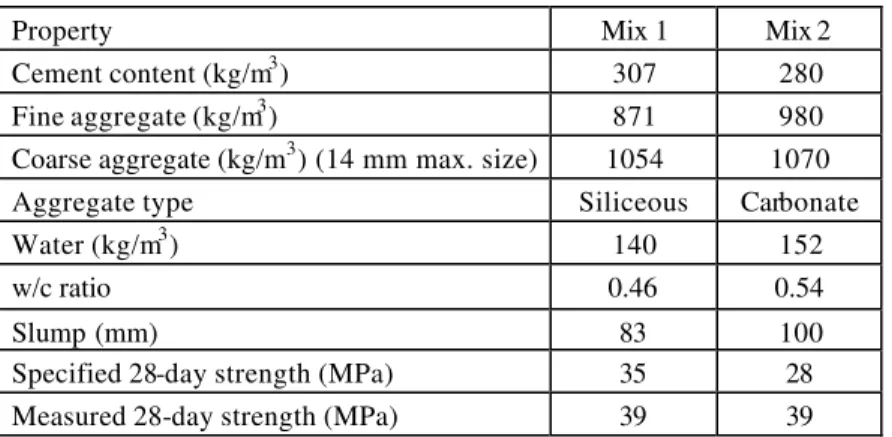
Table 2: Batch quantities and properties of concrete mix
Property Mix 1 Mix 2
Cement content (kg/m3) 307 280
Fine aggregate (kg/m3) 871 980
Coarse aggregate (kg/m3) (14 mm max. size) 1054 1070
Aggregate type Siliceous Carbonate
Water (kg/m3) 140 152
w/c ratio 0.46 0.54
Slump (mm) 83 100
Specified 28-day strength (MPa) 35 28
Measured 28-day strength (MPa) 39 39
During fabrication of the specimens, thermocouples were installed within the concrete and on the internal reinforcing steel at column mid-height for measuring temperatures at various locations over the cross section. Columns 2 and 3 were also instrumented with thermocouples to record the temperatures at the EI -VG interface, the VG-FRP interface, and the FRP-concrete interface. Further details on material characteristics, column fabrication, and instrumentation are given by Bisby [6], Lie and Celikkol [1] and Kodur and Lie [10].
3.2 Test Conditions and Procedures
The columns were installed in a specialized testing furnace, built for testing loaded columns under fire exposure [11], by bolting the columns’ steel endplates to a loading head at the top and to a hydraulic jack at the bottom – a fixed-fixed end condition. The length of the columns exposed to fire was ap proximately 3000mm. However, at high temperature the stiffness of the unheated column ends, which is high in comparison to
that of the heated portion of the column, contributes to a reduction in the columns’ effective length. Therefore, for the columns tested herein, an effective length of approximately 2000mm represents experimental behaviour.
All columns were tested under sustained concentric axial compressive load. Column 1 was subjected to a load of 1431kN, which is equal to 66% of the ultimate load according to CSA-A23.3 [7]. Columns 2 and 3 were both subjected a load of 2515kN, which is about 73% of the ultimate load based on the ISIS Canada design guidelines [8]. Details of the load calculations for these columns are discussed by Bisby [6].
During the tests, the columns were exposed to heat in such a way as to follow, as closely as possible, the CAN/ULC-S101 [12] standard time -temperature curve. The columns were considered to have failed and the tests were terminated when the hydraulic jack could no longer maintain the load.
4. Results and Discussion
In this section, results from the experimental studies are used to illustrate the comparative behaviour of the three columns. The columns had similar characteristics, except for the overall size of the column and the type of aggregate used. The type of aggregate did not significantly influence the behaviour of Columns 2 and 3, as the temperatures in concrete in these columns remained well below the temperature (about 500°C) at which aggregate begins to play an important role. No unprotected FWRC columns were tested, since results of previous (unpublished) fire endurance tests have shown that FWRC columns without fire protection tend to perform poorly since the FRP wrapping is lost within less than one hour of fire exposure.
4.1 Variation of Temperatures
The temperature-time curves at various locations in the concrete are plotted for Column 1 in Fig. 1, which shows that the furnace temperature closely followed the standard temperature-time curve. The temperatures inside the concrete rose rapidly to
about 100°C, after which point
the temperature continued to increase, although at a decreased rate. This behaviour is due to the evaporation of moisture from
the concrete at 100°C and to the
thermally -induced migration of
Figure 1 – Variation of temperatures as a function of time for Column 1
Time (min) 0 60 120 180 240 300 Temperature ( oC) 0 200 400 600 800 1000 1200 ULC-S101 Furnace 38 mm Depth Vert. Rebar 100 mm Depth
moisture toward the centre of the column [13]. Failure of the column occurred when the temperatures at the centre of the column reached about 400°C.
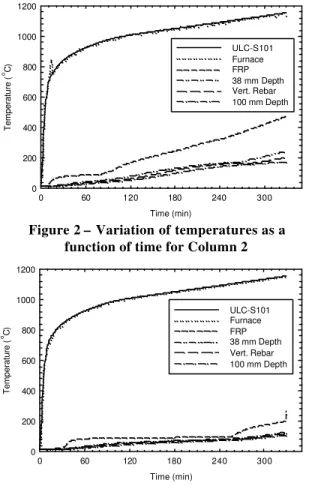
Figures 2 and 3 show temperatures recorded at various locations in Columns 2 and 3 during exposure to fire. The figures show that the temperature of the FRP wrap remained less than 100°C for an extended period of time (for up to 4 hours for Column 2). This was due to the provision of the requisite thicknesses of the VG/EI
insulation system on the
columns, which maintained the temperatures at low levels for a prolonged duration. The temperatures in Column 2 were generally lower than those observed in Column 3, and this can be attributed to the fact that Column 3 was protected with approximately half the thickness of fire insulation as was applied to Column 2. Unlike Column 1, the temperatures of the steel reinforcing bars and internal concrete for Columns 2 and 3 were significantly lower (below 200°C for most of the fire exposure), as compared with Column 1, where temperatures in excess of 800°C and 650°C were observed in the concrete and steel, respectively. Since temperatures of less than 200ºC are not structurally significant in terms of deterioration of mechanical properties for either concrete or steel, it can be stated with confidence that the FWRC columns maintained at least their full unwrapped axial load-carrying capacity for the full 5-plus hour duration of the tests. It is difficult to state conclusively whether the FRP wrap remained effective until the end of the tests. Tests on the specific FRP materials themselves are required to determine their effectiveness at elevated temperature.
Figure 3 – Variation of temperatures as a function of time for Column 3
Time (min) 0 60 120 180 240 300 Temperature ( o C) 0 200 400 600 800 1000 1200 ULC-S101 Furnace FRP 38 mm Depth Vert. Rebar 100 mm Depth
Figure 2 – Variation of temperatures as a function of time for Column 2
Time (min) 0 60 120 180 240 300 Temperature ( o C) 0 200 400 600 800 1000 1200 ULC-S101 Furnace FRP 38 mm Depth Vert. Rebar 100 mm Depth
4.2 Variation in Axial Deformations
The variation in axial deformation with fire exposure time is shown in Fig. 4 for all three columns. The RC column initially expands, until the reinforcement yields at elevated temperature, and then contracts, eventually leading to failure. The deformation during fire exposure results from several factors such as load, thermal expansion, and creep. The initial deformation of the column was mainly due to the thermal expansion of concrete and steel. While the effect of load and thermal expansion is significant in the intermediate stages, the effect of creep becomes pronounced in the later stages due to the high fire temperature. The contraction of the column later in the exposure is mainly due to loss of strength and stiffness of the concrete and steel as the internal temperatures increased.
Most of the deformation in the FWRC columns, which displayed only a very slight elongation, is due to a mild thermal expansion. The magnitude of the expansion was greater for Column 3, which experienced slightly higher internal temperatures than Column 2 due to a smaller insulation thickness. Unlike Column 1, there was no contraction observed for Columns 2 and 3 until late in the tests when the loads were increased in an effort to fail the columns. This can be attributed to the beneficial thermal insulation provided by the fire protection, which resulted in minimal temperature increases in the concrete and internal reinforcing steel for these members, and consequently no significant reduction in strength or stiffness. Beyond 5 hours of fire exposure, the FWRC columns displayed a sudden and severe contraction, which can be attributed to increasing the applied load beyond 5 hours in an attempt to induce failure, which occurred at about 5.5 hours of exposure at a load of about 180% of that required for service load conditions.
4.3 Fire Endurance
Table 1 provides a comparison of the fire resistance ratings achieved for the three columns, where fire resistance is defined in terms of the columns’ ability to maintain their sustained service load for the required duration during exposure to the standard fire. For Column 1, the fire resistance was 245 minutes, while for Columns 2 and 3, it was more than 330 minutes – even under increased (strengthened) service loads. The superior fire resistance of the FWRC columns, as compared to the conventional RC column, can be
Figure 4 – Axial deformations as a function of time for Columns 1, 2 and 3
Time (min) 0 60 120 180 240 300 360 Axial Deformation (mm) -15 -10 -5 0 5 10 Column 1 Column 2 Column 3
attributed to the fire protection provided by the VG/EI system. Also, Column 1 was fabricated from siliceous aggregate concrete which typically results in lower fire resistances as compared with carbonate aggregate concrete [14].
Column 1 experienced sudden failure in compression under service load, with approximately 30% of the cover concrete spalling at that time. Columns 2 and 3 failed by crushing and spalling of concrete, although only after the applied load was increased to more than 180% of the required service load (and after 5 hours of fire exposure). Figure 5 shows an FWRC column before testing and after failure.
4.4 Fire Protection System
Columns 2 and 3 did not display any significant signs of failure for at least 5 hours of fire exposure under the 2515kN strengthened service load, which can be attributed primarily to the performance of the VG/EI fire protection system that was applied to both of these columns.
For both columns the EI intumescent coating activated within the first 3 to 4 minutes of the test. Expansion of the EI coating was complete within 10 minutes of fire exposure, and the expanded EI char began to debond from the columns’ surface in both tests within 15 minutes of exposure. The beneficial effects of the EI coating on the overall fire performance of the column are twofold. First, the EI acts as an initial line of defence against fire, and significantly reduces the temperatures experienced in the column in the early stages of the fire (based on the in formation form other studies). Second, the EI paint, which is applied to the outer surface of the VG shortly after the VG is applied to the column, acts as an impervious membrane and traps moisture inside the VG. Thus, the VG has high moisture content when exposed to fire, and its insulating characteristics are enhanced. When exposed to flames, Tyfo® VG plaster releases chemically-combined water in the form of water vapour, which helps to maintain the plaster’s temperature near 100°C until all of the water has been driven off as steam. Meanwhile, the insulating action of vermiculite filler delays the release of steam and retards the transmission of heat, thus improving the overall fire -proofing characteristics.
Figure 5 – An FWRC column (Column 2) before testing and after failure
The VG insulation performed well under fire exposure, and remained intact until the end of the tests, when the load was increased dramatically and explosive concrete crushing/spalling caused it to debond from the column. The only change that was observed in the appearance of the VG insulation during the fire exposure was the formation of cracks, generally less than 5 mm wide, which gradually appeared and widened as the test progressed. The location of the cracks appeared to be associated with the thickness of the VG and the location of installation joints in the material. From a structural point of view, the fire-protected FWRC columns behaved similarly to, or better than, the unwrapped RC column.
5. Ongoing Research
The main objective of the experimental studies reported above was to obtain test data for the development of computer models that can predict the behaviour of FRP-wrapped reinforced concrete columns under fire conditions. In the past, the fire resistance of structural members could be determined only by testing. In recent years, however, the use of numerical methods for the calculation of the fire resistance of various structural members has been gaining acceptance. These emerging calculation methods are far less costly and time consuming than full-scale fire endurance testing.
The development of computer programs for the calculation of the fire resistance of FRP-wrapped, reinforced, or strengthened RC members is in progress as part of this ongoing project. To validate these models, further fire tests are being conducted on full-size FRP -wrapped RC columns and FRP-strengthened RC beams, with and without supplemental fire protection systems. Once validated, the computer programs will be used to carry out detailed parametric studies to investigate the influence of various parameters, such as concrete strength and load intensity, on the fire endurance. Data from the parametric studies will be used to develop fire design guidelines for FRP-reinforced concrete systems.
6. Concluding Remarks
Based on the studies completed so far, the fo llowing conclusions have been drawn:
• Unlike conventional RC columns, FWRC columns require suitable fire protection, in
most cases, to achieve the required fire endurance ratings under increased service loads. The performance of protected FWRC columns at high temperatures can be similar to, or better than, that of conventional RC columns.
• FRP-wrapped RC columns protected with the fire protection system discussed herein
are capable of achieving fire endurance ratings of 5 hours or more according to CAN/CSA-S101 requirements, under full service loads.
• The supplementary insulation described herein is an effective fire protection system.
Visual observations made during the fire tests indicated that the insulation remained intact for more than 5 hours of exposure to the standard fire.
• Further studies, currently in progress, will generate additional data on the fire endurance of FRP-RC members and will identify the conditions under which these members can be safely used.
Acknowledgements
The research presented in this paper is the result of a partnership between NRC, the Intelligent Sensing for Innovative Structures Network (ISIS Canada), Queen’s University, Canada, and industrial partners Fyfe Company LLC and WBA Degussa Company. The authors would like to ackn owledge these organisations for their support of, and participation in, this important research. The authors would also like to thank NRC Technical Officers J. Hum, J. Latour, P. Leroux and R. Monette for their assistance with the experiments.
References
1. Lie, T.T. and Celikkol, B., “Method to calculate the fire resistance of circular reinforced concrete columns,” ACI Mat. J., V. 88, No. 1, 1991, pp. 84-91.
2. Kodur, V.K.R., “Fire resistance requirements for FRP structural members,”
Proceedings of the Annual Conference of the Canadian Society for Civil Engineering,
Regina, Saskatchewan, 2001, pp. 83-95.
3. Bisby, L.A., Green, M.F., Kodur, V.K.R., "Fire Endurance of FRP-Confined Concrete Columns", Submitted to ACI Struct. J., 2003, 29 pp.
4. Blontrock, H., Taerwe, L., and Matthys, S., “Properties of Fiber Reinforced Plastics at Elevated Temperatures with Regard to Fire Resistance of Reinforced Concrete Members,” Fibre Reinforced Polymer Reinforcement for Reinforced Concrete
Structures, American Concrete Institute, Detroit, MI, 1999, pp. 43 -54.
5. Kodur, V.K.R., and Baingo, D., “Fire resistance of FRP reinforced concrete slabs,”
IRC Internal Report No. 758. National Research Council of Canada, Ottawa, 1998, 37
pp.
6. Bisby, L.A., “Fire behaviour of fibre-reinforced polymer (FRP) reinforced or confined concrete,” Ph.D. Thesis, Department of Civil Engineering, Queen’s University, Kingston, ON.
7. CSA, “Design of Concrete Structures,” CAN/CSA A23.3-94, Canadian Standards Association, Ottawa, ON, 1994.
8. ISIS, “Design Manual No. 4: Strengthening reinforced concrete structures with externally bonded fiber reinforced polymers,” Intelligent Sensing for Innovative Structures Canada, Winnipeg, MB, 2001.
9. ACI, “Guide for the design and construction of externally bonded FRP systems for strengthening concrete structures,” ACI 440.2R-02, American Concrete Institute, Farmington Hills, MI, 2002.
10. Kodur, V.K.R., Lie, T.T., "A computer program to calculate the fire resistance of rectangular reinforced concrete columns," Proceedings of the Third Cana dian
Conference on Computing in Civil and Building Engineering, Montreal, PQ, 1996, pp.
11-22.
11. Lie, T.T., “New Facility to Determine Fire Resistance of Columns,” Can. J. of Civ.
Eng., V. 7, 1980, pp. 551-558.
12. CAN/ULC, “Standard Methods of Fire Endurance Tests of Building Construction and
Materials,” CAN/ULC-S101-M89, Underwriters’ Laboratories of Canada,
Scarborough, ON, 1989.
13. Lie, T.T., “Structural Fire Protection,” American Society of Civil Engineers Manuals
and Reports on Engineering Practice No. 78 ., ASCE, New York, NY, 1992.
14. Kodur, V.K.R., Harmathy, T. Z., "Properties of building materials," SFPE Handbook
of Fire Protection Engineering , 3rd edition, National Fire Protection Association,