Publisher’s version / Version de l'éditeur:
proceedings of the 23 International Congress on Applications of Lasers and
Electro-Optics 2004, 2004-10-08
READ THESE TERMS AND CONDITIONS CAREFULLY BEFORE USING THIS WEBSITE.
https://nrc-publications.canada.ca/eng/copyright
Vous avez des questions? Nous pouvons vous aider. Pour communiquer directement avec un auteur, consultez la première page de la revue dans laquelle son article a été publié afin de trouver ses coordonnées. Si vous n’arrivez pas à les repérer, communiquez avec nous à PublicationsArchive-ArchivesPublications@nrc-cnrc.gc.ca.
Questions? Contact the NRC Publications Archive team at
PublicationsArchive-ArchivesPublications@nrc-cnrc.gc.ca. If you wish to email the authors directly, please see the first page of the publication for their contact information.
NRC Publications Archive
Archives des publications du CNRC
This publication could be one of several versions: author’s original, accepted manuscript or the publisher’s version. / La version de cette publication peut être l’une des suivantes : la version prépublication de l’auteur, la version acceptée du manuscrit ou la version de l’éditeur.
Access and use of this website and the material on it are subject to the Terms and Conditions set forth at
Hardness and Wear Behaviour of TiC-Al/Si Composite Coatings Made
by Laser Cladding onto Al Substrate
Dubourg, L.; Hlawka, F.; Cornet, A.
https://publications-cnrc.canada.ca/fra/droits
L’accès à ce site Web et l’utilisation de son contenu sont assujettis aux conditions présentées dans le site LISEZ CES CONDITIONS ATTENTIVEMENT AVANT D’UTILISER CE SITE WEB.
NRC Publications Record / Notice d'Archives des publications de CNRC:
https://nrc-publications.canada.ca/eng/view/object/?id=d028d38b-eb8f-48d1-9f85-2dc8516cce1c https://publications-cnrc.canada.ca/fra/voir/objet/?id=d028d38b-eb8f-48d1-9f85-2dc8516cce1cIMI2004-106133-G CNRC 47569
Proceedings of the 23rdInternational Congress on Applications of Lasers and Electro-Optics 2004
HARDNESS AND WEAR BEHAVIOUR OF TIC-ALISI COMPOSITE COATINGS MADE BY LASER CLADDING ONTO AL SUBSTRATE.
L. Dubourg\ F. Hlawka2,A. Cornee
1Aluminium Technology Centre, National Research Council Canada 501 Soul. de l'Universite, Saguenay (Quebec) Canada 2Laboratoired'ingenieriedesSurfacesde Strasbourg,ENSAIS
24 bd de la victoire, 67000 Strasbourg, France.
Abstract
This study investigates the influence of the composition and microstructure of laser cladded metal-matrix composite (MMC) coatings onto the hardness and the adhesive wear behaviour. Laser cladding was carried on pure AI substrate using a cw Nd:YAG laser and a coaxial powder injection system. Composite coatings were made of an Al/Si matrix containing 0 to 40 wt.% Si and a TiC reinforcement powder with a volume :tractionranging form 0 to 30 %. Samples were characterised using an optical microscopy, XRD, hardness measurement and adhesive wear testing (ball-on-disk device). Si content and TiC reinforcement ratio increased the bulk coating hardness up to a maximum value of 250 HV5. For a fixed TiC ratio, a linear correlation was observed between hardness and Si content. Depending on the TiC volume :tractionand Si content, the wear behaviour appeared a mild, severe or surface fatigue wear. Hypoeutectic Al/Si alloys without TiC reinforcement showed a severe wear dominated by extensive plastic flow and significant wear scars. With the TiC addition, a mild wear, characterized by a low wear rate and a fine damage, was observed. In the case of hypereutectic alloys without TiC reinforcement, wear was also mild and the wear rate was similar to the one observed on AI-12Si /30 vol.% TiC coating. Addition of TiC reinforcements accelerated the wear of these hypereutectic alloys due to the surface fatigue.
Introduction
Laser cladding consists in covering the substrate surface with a coating of a different nature. This process can be carried out in different ways: wire feeding, lateral [1] or coaxial [2] powder injection. In the case of powder injection, the cladding powder is injected into the laser beam by an inert gas flow. The energy delivered by the laser is absorbed both by the powder stream and the substrate material. This enables the melting of the in-flight particles and the fusing of the powder onto the substrate surface. A clad is formed
by moving the sample under the laser beam. An uniform layer is obtained by partially overlapping individual clads. A slight dilution of the cladding material into the substrate generates a perfect metallurgical bonding between them. Over the last fifteen years, many studies on aluminium laser surface treatment have been carried out with the objective of improving the mechanical characteristics of cladded coatings (hardness, elastic modulus, wear resistance). Several authors have already investigated the formation of intermetallic aluminium compounds (alloys AI-Ni [3], AI-Fe [4], AI-Cu [5], AI-Mo [6] and AI-Cr [7]) and silicon precipitation in AI-Si alloys [8]. Another field of study consisted in the development of metal matrix composites (MMC) coatings. These materials are composed of hard reinforcement particles distributed in a softer metal matrix. In the case of aluminium, the reinforcements are more often silicon carbide [9] and titanium carbide [10]. In the present study, coatings are made :trom an aluminium matrix containing 0 to 40 wt.% Si and a TiC volume :traction ranging :trom0 to 30 %. The laser cladding is carried out using a coaxial powder injection system. The coating microstructure is analysed by optical microscopy and XRD and mechanical properties are characterised by hardness and adhesive wear resistance.
Experimental set-up
Laser cladding was carried out using a 2000 W continuous wave Nd:YAG laser of 1.064-J.1m wavelength and a 1 rom diameter optical fiber. At this wavelength, the absorption coefficient of the aluminium substrate is about 25%, which is two times higher than that obtained with a CO2 laser at a wavelength of 10.6 J.1m[11]. A lens with a 300 rom focal length was used to focus the laser beam. The selected parameters were as follows: the laser beam power was adjusted to 1700 W on the workpiece surface, with a spot diameter of 3 rom, the calculated power density is then 240 W.rom-2.The angle between the laser beam and the surface sample was set at 85°.
Normal incidence was not used to avoid the risk of beam reflection, which could damage the optical fibre or the laser cavity. Samples were placed on an X-Y table and the sample translation velocity was varied :6:om7.10-3to 1.7.10-2m.s.1 depending on the coating composition. Laser treated specimens were circular to allow wear tests with a ball-on-disk-type device (see Fig. 1). Substrates of commercial aluminium (99.5% AI) were used; their size is 060 x 8 mm (see Fig. 1). Their surface was sand-papered using a 120-grit SiC paper followed by cleaning with acetone prior to laser cladding. This surface preparation increased the energy coupling between the laser beam and the aluminium surface [12]. Premixed powders of pre-allied AI-Si with varying Si content and pure TiC were injected inside the laser beam at a rate ranging :6:om0.13 to 0.2 g.S.I. Argon at 1 bar pressure and 0.05 1.s.1flow rate was used as a carrying gas.
Microstructure examination was performed by optical microscopy after mechanical polishing (diamond with 1 ~m grain size) and chemical etching using Keller's reagent. Phases were identified by XRD using a Siemens D5000 dif:6:actometer (Cu-Ka radiation). Vickers hardness measurements were performed with a load of 50 N on the coated surface after machining. Loads lower than 10 N cannot be used for bulk hardness measurement owing to the large size (50-150
!lm) and dispersion of TiC particles. In order to characterise properly the hardness of MMCs, the size of the indentation mark must be large in comparison with the size of the constituents. Moreover, for all these measurements, the tip penetration was still 10 times lower than the coating thickness to avoid substrate influence. A ball-on-disk-type tribometer was used for wear experiments under dry-sliding conditions. The laser coating was machined to obtain a flat surface of about 2 mm wide (Ra = 6 !lm) and cleaned with acetone. A tungsten carbide ball (diameter of6 mm, hardness of 1400 HVO.2)slided on the machined circular coating (see Fig. 1) under a load of 5 N as the substrate was rotated. The tangential speed was 0.4 m.s-I and the sliding distance was fixed at 1600 m. The wear experiments were not carried out under a controlled atmosphere. Wear was characterised using the volume loss of the specimen and by observing the wear scars. The volume loss was calculated :6:om the coating density, which can be adequately estimated using the law of mixture between the matrix and the carbides [13], and the measurements of the sample mass loss (measured with an accuracy of
:f: 0.1 mg). This approximation was valid, as the
carbides were not dissolved in the matrix and the coatings were not porous. Observation of wear scars was performed by microtopography and scanning electron microscopy (SEM). The mass variation of the
we ball was not measured. Microtopographic data of wear tracks were obtained by an extended field confocal microscope [14] with a vertical resolution of 0.01 !lm and lateral resolution of 2 !lm. The topography was measured on a 5 x 3 mm2surface, with a sampling step of 2 !lm in the horizontal plan. The SEM used was a Phillips type XL30.
---
-
...
~"J
.j
:.
I'J
,~,
--
..20mm
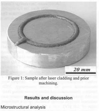
Figure 1: Sample after laser cladding and prior machining.
-..
-...
Results and discussion
Microstructural analysis
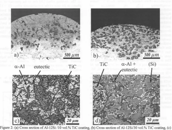
Coatings were produced with premixed powders of Al alloys containing 0, 12, 30 or 40 wt.% Si (matrix) and TiC particles (reinforcement) with volume :6:actionsof 0, 10 or 30%. The coatings were :6:eeof pores or cracks and showed a good metallurgical bonding to the substrate. As shown in Fig. 2.a and 2.b, the typical coating thicknesses were around 1.2 mm for 0 and 10 vo1.% TiC and 0.9 mm for 30 vo1.% TiC. These coatings were uniform: microstructure scale and type were similar through the entire coatings. Depending on the silicon content, the microscopic structure of the matrix was either hypoeutectic (Si content ~ 12 wt.%) or hypereutectic (Si content> 30 wt.%). Up to 12 wt.%Si, the microstructure was composed of intact TiC particles, white a-AI primary dendrites and a dark Al/Si eutectic (see Fig. 2.c). At 12 wt.% Si, the single eutectic microstructure predicted by the binary diagram was not observed. This phenomenon can be explained by the rapid solidification rate peculiar to the laser process. Under dynamic conditions, zones of phase existence can be modified and the eutectic composition is shifted to the silicon side of the diagram in case of rapidly solidified AI-Si alloys [15]. Similar phenomenon can be observed in AI-Cu alloys carried out by laser surface treatments [5].
a-AI
eutectic
TiC
Figure 2: (a) Cross section of AI-12Si /10 vo1.%TiC coating, (b) Cross section of AI-12Si/30 vo1.%TiC coating, (c) Micrograph of AI-12Si /30 vo1.%TiC coating, (d) Micrograph of AI-40Si /30 vo1.%TiC coating.
With Si content higher than 30 wt.%, the microstructure consisted of intact TiC particles, primary faceted Si crystals surrounded by a-AI dendritic halos and branched Al/Si eutectic adjacent to the AI halos (see Fig. 2.d). This is a non-equilibrium microstructure, which can be explained by the fast solidification rate occurring during laser processing. The Si particles nucleate from the liquid by a heterogeneous mechanism and grow into the melt, creating Si-depleted zones in the surrounding aluminium solvent. During equilibrium solidification, this zone is enriched again in Si by diffusion from the nearby liquid. In case of laser surface treatment, the solidification is too rapid to allow diffusion to take place and, consequently, the local AI concentration becomes sufficient to nucleate a-AI phase. This a-AI phase appears as halos surrounding Si particles and its formation stops their growth. As hypoeutectic matrix, this type of microstructure was not altered by the TiC concentration.
Microscopic observations revealed no superficial dissolution of the carbide particles due to partial melting. Even though the TiC melting temperature is higher than the boiling point of aluminium, this can be possible as the absorption coefficient of TiC at the laser wavelength is three times than the one of aluminium [9]. Consequently, the TiC particles can be melted during the injection while the AI powder is not boiled. Furthermore, XRD analysis did not show the presence of A4C3 aluminium carbide that result from the TiC melting inside the AI matrix. As shown in Fig. 3, XRD analysis detected only the AI, Si and TiC. Nevertheless, this observation should be completed by a more detailed study, as XRD is only sensible to a phase volume fraction higher than 5%. Moreover, Park and Lucas [16] have proved that A4C3 carbides can precipitate like hexagonal platelets onto the reinforcement surface. These platelets were 0,7 Ilm thick and 3 Ilm wide on the average. The small size of these platelets makes their detection by XRD or optical microscopy difficult. In any event, A4C3 carbide precipitation must be avoided as it results in: (i)
degradation of mechanical properties due to the matrix
strengthening [17], (ii) reduction of
reinforcement/matrix interfacial strength and degradation of fracture behaviour of MMC due to the brittleness of the MC3 phases surrounding the TiC reinforcements [17], (iii) increase in corrosion sensitivity. Due to its hydrophilic nature, MC3 is decomposed into aluminium hydroxide Al(OH)3 and methane CH4 in moist environments. This promotes accelerated fatigue crack growth rates and reinforcement debonding in MMC [9]. Studies showed that the use of hypereutectic AlISi matrix (Si higher than 30%) can inhibit the A4C3 precipitation in MMC laser cladding [9] or MMC powder metallurgy [18]. This is based on the principle that Si activity will be enhanced according to the amount of Si within the AI matrix. Since Si is more carbide-forming than AI, SiC will precipitate preferentially to MC3. However, as observed later in this study, the use of hypereutectic Al/Si matrix can decrease the adhesive wear resistance of laser cladded MMC. A possible way to increase the wear resistance is the addition ofTi instead ofSi to the matrix, because Ti is more carbide-forming than AI [19]. This way can lead to the in-situ precipitation of secondary TiC reinforcement instead of MC3 in the matrix or around the primary TiC particles.
3000 ~ ;;; ::;:"1~
~E-~
2000~
'-'
'<I) .'1::'" s:: <I) 1:: 1000 ... ~ ;;;~
u E= ~ ;;; ::;:" ~"i
$
;;; uE= 0 w ~ @ W 100 2ee)Figure 3: XRD peaks (AI-12Si /30 vo1.%TiC coating). Hardness measurements
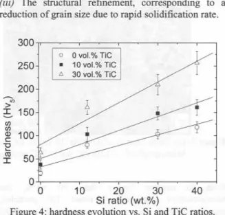
Fig. 4 shows the results of Vickers hardness measurements. Each value is an average of six measurements taken with a load of 50 N on the coating surface after machining. By increasing the Si proportion from 0 to 40 wt.% without carbide reinforcement, a hardness increase from 19 ::1:2to 118 ::1:10HV5 was observed. Fig. 4 indicates a linear correlation between hardness and Si content. In the absence of carbide reinforcement, hardness improvement can be explained by:
-(i)The shielding effect [20] due to the presence of Si phases in the case of the hypereutectic alloys (Si > 12 wt.%). In fact, these large (10-40 !!m) and hard (hardness of 1200 HVO.2) particles create a metallic matrix composite (MMC) with the softer and finer eutectic/a-AI matrix. Consequently, during the load, elastic and plastic strains are incompatible between the Si reinforcements and the eutectic/a-AI matrix. This phenomenon reduces the load stress and increases hardness.
(ii) The solution hardening of a-AI phase (supersaturation of a-AI primary dendrites) in case of hypoeutectic alloys (Si lower than 12 wt.%). The high quench rates, which can be attained by laser processing, cause an increased retention of Si in solid solution within a-AI phase.
(iii) The structural refinement, corresponding to a reduction of grain size due to rapid solidification rate.
300 250
0 0 vol.% TiC
.
10 vol.% TiCI:> 30 vol.% TiC 200 ---'" > !. 150 C/) C/)
~
100 "E~
50 ,.1
1 0 0 10 20 30 40 Si ratio (wt.%)Figure 4: hardness evolution vs. Si and TiC ratios. As shown in Fig. 4, TiC reinforcement also increases the bulk hardness. For a fixed TiC concentration, this figure indicates a linear correlation between hardness and Si content. Compared with coatings those are not reinforced with TiC particles, the bulk hardness was increased by a factor of approximately 1.5 and 2.5 for 10 vo1.%and 30 vo1.%TiC addition, respectively. The maximum hardness of 250 HV5 was reached with AI-40Si /30 vo1.% TiC coating. This hardness improvement can be explained by the shielding effect [20] between the TiC particles and the Al/Si matrix. TiC particles have a high hardness (2500 HVO.2) and large size (50-150 !!m) compared with the microstructural features found in the Al/Si matrix. Consequently, their presence decreases the stress during the load due to the incompatibility of strains between these particles and the matrix, and increases the hardness.
Wear experiments
Wear was characterised by the volume loss of the specimen: Table 1 shows these results as a function of Si content and TiC ratio. The volume loss was calculated ttom the sample mass loss and the coating density (estimated by the law of mixture between the matrix and TiC densities [13]). This approximation was correct because the carbides did not dissolve in the matrix, as discussed earlier.
Table 1: Wear rate (10-3mm3.m-J)vs. TiC ratio and Si content of the Al/Si matrix.
Without TiC reinforcement, the increase of Si content improves the wear behavior of the coatings: the wear
200 !Jrn
a)
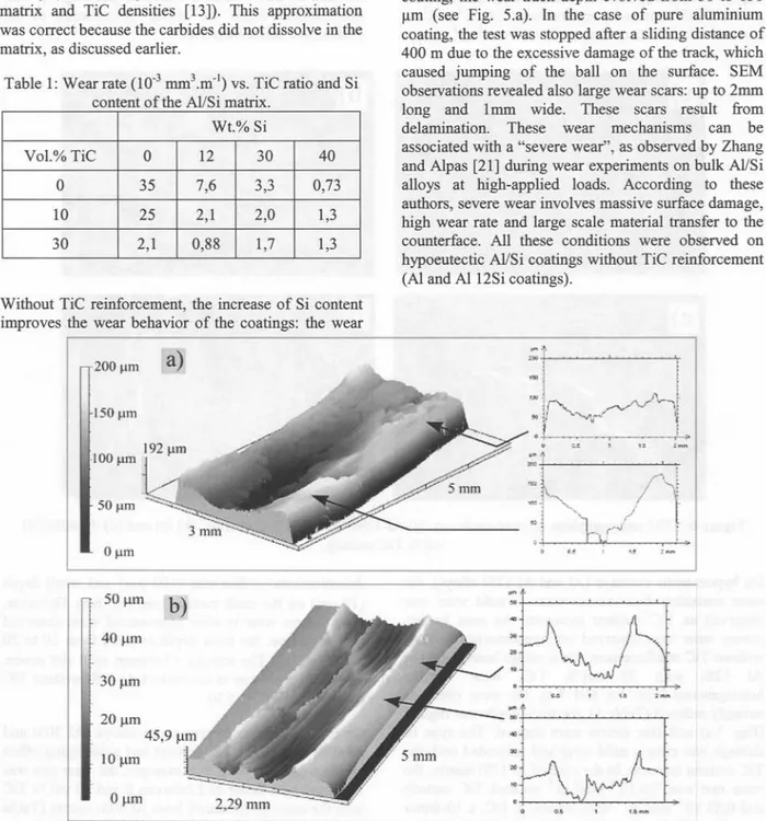
rate decreases ttom 35 to 0,73 10-3 mm3.m-Jwhen Si increases ttom 0 to 40 wt.% (see Table 1). In the case of hypoeutectic Al/Si alloys (Al and Al12Si coatings), wear tests led to a strong damage of the coating surface, with material transfer ttom the sample to the ball. Plastic zones were noticed where the material is pushed leading to a wave type profile (see Fig. 5). After a sliding distance of 1600 m onto the Al 12Si coating, the wear track depth evolved ttom 50 to 150
/lm (see Fig. 5.a). In the case of pure aluminium coating, the test was stopped after a sliding distance of 400 m due to the excessive damage of the track, which caused jumping of the ball on the surface. SEM observations revealed also large wear scars: up to 2mm long and 1mm wide. These scars result ttom delamination. These wear mechanisms can be associated with a "severe wear", as observed by Zhang and Alpas [21] during wear experiments on bulk Al/Si alloys at high-applied loads. According to these authors, severe wear involves massive surface damage, high wear rate and large scale material transfer to the counterface. All these conditions were observed on hypoeutectic Al/Si coatings without TiC reinforcement (Al and Al12Si coatings).
-g
... lro.:
('.
..-~K,
.1
. .. r-! !.
,. 'ftft
~ 150 !Jrn 50f.tm 0f.tID 50 JlIIlb)
40).l.m 30flm 20J.lm 45,9 /lm 10 JlIIl .. ... .. .. ..0 ).I.m
2 29mm
,
=
.
.
...
.
tA-I
Figure 5: Microtopographies and transverse sections of wear tracks on: (a) a coating performed ttom Al12Si, (b) a coating performed ttom Al40Si.
Wt.% Si
Vol.% TiC 0 12 30 40
0 35 7,6 3,3 0,73
10 25 2,1 2,0 1,3
In the case of hypereutectic Al/Si alloys (AI 30Si and Al40Si coatings), we noted a homogeneous wear track and the formation of fine black debris. For the AI 40Si coating, for example, the track depth was around 20 !lm after 1600 m sliding distance, as shown in Fig 5.b. These wear tracks were also characterised by the lack of strongly delaminated zones. Moreover, the wear rate was significantly lower than that observed with the hypoeutectic alloys: for AI 40Si coating, the wear rate was 0,73.10-3mm3.m-Icompared with 7,6.10-3mm3.m-I in case of A7,6.10-3mm3.m-Il2Si coating or 35.10-3mm3.m-7,6.10-3mm3.m-Iin case
of pure Al coating. Actually, the wear rate was reduced by a factor ranging from 10 to 50. The same phenomenon was also noticed with the AI 30Si coating. This type of damage presents the characteristics of "mild wear" as observed by Zhang and AIpas [21] during wear experiments on bulk Al/Si alloys at low-applied loads. The transition from severe to mild wear may result from the bulk hardness increase as the Si content increases (see Fig. 4). This enhancement limits the plastic deformation of the coating and surface asperities.
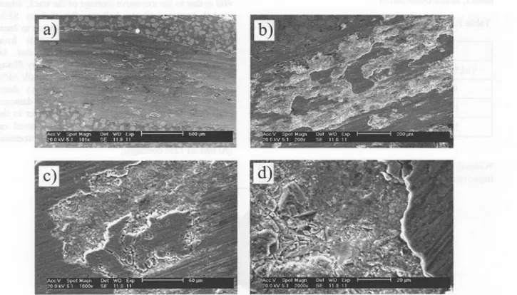
Figure 6: SEM micrographies of wear tracks on: (a) AI-12Si /30 vo1.%TiC coating, (b) (c) and (d) AI-40Si /30 vo1.%TiC coating.
On hypoeutectic coatings (AI and AI I2Si alloys), the same transition from severe wear to mild wear was observed as TiC content increases. As seen earlier, severe wear was observed on hypoeutectic coatings without TiC reinforcement. On coatings based on AI or
AI I2Si with 30 vo1.% TiC, wear became
homogeneous (Fig. 6.a and 7.a), the wear rate was strongly reduced (Table 1), the track depth was regular (Fig. 7.a) and fine debris were formed. The type of damage was clearly mild wear and coincided with the
TiC contentincrease.In thecaseof AI12Si matrix,the
wear rate was 7,6.10-3mm3.m-I without TiC carbide and 0,88.10-3mm3.m-Iwith 30 vo1.%TiC, a lO-factor improvement. For pure AI matrix, the improvement reached a 20-factor with respective wear rates of35.10-3 and 1,8.10-of35.10-3 mmof35.10-3.m-I for 0 and of35.10-30 vo1.% TiC. Moreover, SEM observations also revealed some
delaminations of fme size (100 !lm) and small depth (10 !lm) on the track surface (see Fig. 6.a). However, zones where wear is more pronounced were observed on the surface: the track depth evolved from 10 to 20 !lm (Fig. 7.a). The transition between mild and severe was not complete as in the case of AI40Si without TiC reinforcement (Fig. 5.b).
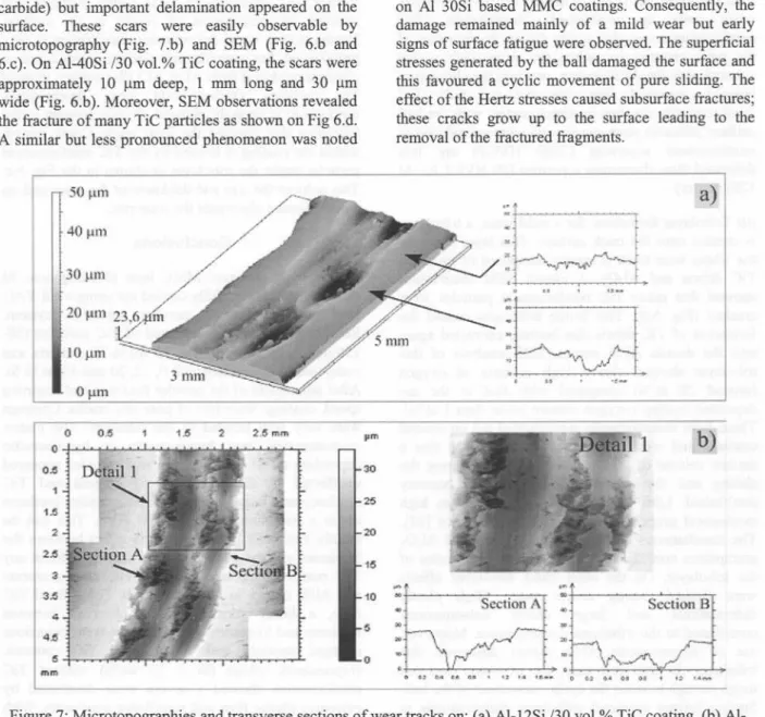
On the contrary, in hypereutectic alloys (AI 30Si and AI40Si alloys), the TiC content had a damaging effect on the wear behaviour. For example, the wear rate was increased by a factor of2 between 0 and 30 vo1.%TiC with the coatings produced from AI 40Si matrix (Table 1). Wear tracks were globally uniform and shallower (around 15 !lm for AI-40Si /30 vo1.% TiC coating compared with 20 !lm for a AI-40Si coating without
carbide) but important delamination appeared on the surface. These scars were easily observable by microtopography (Fig. 7.b) and SEM (Fig. 6.b and 6.c). On Al-40Si /30 vol.% TiC coating, the scars were approximately 10 11mdeep, 1 mm long and 30 11m wide (Fig. 6.b). Moreover, SEM observations revealed the fracture of many TiC particles as shown on Fig 6.d. A similar but less pronounced phenomenon was noted
50 11m 4Oj,tm 30 ~lIn 10 ~lm OJ,tm 1.5 2 2.5 mm pm
Tf
r1~
-~
".
t
Itoo
15on Al 30Si based MMC coatings. Consequently, the damage remained mainly of a mild wear but early signs of surface fatigue were observed. The superficial stresses generated by the ball damaged the surface and this favoured a cyclic movement of pure sliding. The effect of the Hertz stresses caused subsurface fractures; these cracks grow up to the surface leading to the removal of the fractured fragments.
~Q
. .. ,'"-~Q
. t.
.,<-a)
~ll
t'b)
r,.at
~..
~ }',
. ..' . . . ' '. ''' . '. . ' . "'$.. '... .
".. .' ,,0 ...~
'~b:d
10" <II.
.. Section A .. $echon B 5 ,. .. .. ~ 0 ...
...
. .. .. ... . .. 'Ai'-- . U .. .0'.. i U
..-Figure 7: Microtopographies and transverse sections of wear tracks on: (a) AI-12Si /30 vol.% TiC coating, (b) Al-40Si /30 vol.% TiC coating.
According to Deuis et al. [22], adhesive wear mechanisms on Al-based MMC can be explained by 3 phenomena: (i) deformation of the material surface (classical theory), (ii) tribolayer formation and (iii) delamination. According to the previous results, these phenomena can be also applied to the wear mechanisms observed on Al-based MMC laser cladding:
(i)Deformation of the material surface: adhesive wear occurs when surfaces slide against each other and the pressure between the contacting asperities is high enough to cause local plastic deformation [22]. The hardness of the wearing surface determines then the real area of contact between asperities of both
contacting materials. Asperity hardness is therefore considered to be more important than bulk hardness. In the present study, a linear correlation was noted between the TiC content and the bulk hardness. This enhancement can explain the wear track depth reduction as a function of TiC content (see Fig. 5.a and 7.a). A hardness increase causes therefore a bulk plastic deformation reduction, a wear track depth reduction and a transition from severe to mild wear. Regarding surface asperities, SEM observations showed that almost the whole wear track was covered with the ductile Al/Si matrix (Fig. 6.a). The ball pushed the AlISi matrix, which was more ductile than the TiC particles, until covering the reinforcement particles. Consequently, TiC reinforcements did not
0 0.5 0 0.5 1 1,5 2 2.5 3.S 4 4.5 5 mm
limit the local plastic deformation of surface asperities when wear is established. Nevertheless, TiC reinforcements can playa role during the first step of the wear process, i.e. when the wear track is not covered with the Al/Si matrix, or when the aluminium layer is removed (Fig. 6.b, 6.c and 6.d). TiC reinforcements are then in direct contact with the ball surface: adhesive phenomenon and wear are reduced as reinforcement asperities (2500 HVO.2) are less deformed than aluminium asperities (80 HVO.2 for AI 12Si matrix).
(ii)Tribolayer formation: for a mild wear, a tribolayer is created onto the track surface. This layer covering the whole wear track is mainly composed of fractured TiC debris and AI203. A closed SEM observation showed that many TiC reinforcement particles were cracked (Fig. 6.d). This brittle behaviour caused the formation of TiC debris that became encrusted again into the ductile Al/Si matrix. EDS analysis of this tribolayer showed also a high quantity of oxygen (around 20 at.%) compared with that in the as-deposited coating (oxygen content lower than I at.%). These EDS measurements were carried out on several coatings and wear zones. This may indicate that a certain volume of AI203 was precipitated during the sliding and that an oxidation wear was possibly established. Like TiC debris, AI203 oxide has high mechanical properties and high wear resistance [22]. The simultaneous presence of TiC debris and AI203 precipitates contributes to the protective properties of the tribolayer. On the other hand, tribolayer effects were limited during severe wear. High plastic deformations and large debris delaminations contributed to the tribolayer disappearance. Moreover, use of hypereutectic Al/Si matrix destroyed this tribolayer. In this later case, the tribolayer was not tough enough to resist the cyclic movement of the ball. Surface fatigue appeared with large delaminations in the tribolayer (Fig. 6.b, 6.c and 7.b). The tribolayer was then removed and TiC reinforcement particles were uncovered on the wear track. Due to the successive impacts of the WC ball, these TiC particles were then fractured and the wear rate increased. In case of hypoeutectic Al/Si MMC coatings, the tribolayer was ductile enough to limit crack growth and delamination. In fact, a ductile tribolayer must cover the AI-based MMC coatings in order to give an optimal resistance against adhesive wear.
(iii) Delamination mechanism: delamination mechanism occurs in the following sequential steps [22]: (1) cyclic plastic deformation of surface layers by normal and tangential loads, (2) crack nucleation in the deformed layers at inclusions or second-phase particles, (3) crack growth nearly parallel to the
surface, (4) formation of wear debris particles and removal by propagation of cracks to the surface. During severe wear, delamination mechanism is very pronounced. For example, scar size can reach 2 rom on coatings produced from AI or AIl2Si powders without TiC particles. During mild wear, delamination mechanism is strongly reduced. It only appears in the tribolayer that covered the wear track. Crack growth within the coating is limited by the TiC reinforcement particles under the tribolayer as shown in the Fig. 6.c. This reduces the size and thickness of the scars and, as a consequence, decreases the wear rate.
Conclusions
In this work, AI-based MMC laser cladding onto AI substrate was successfully carried out using a Nd:YAG laser and a coaxial powder injection system. Reinforcements were constituted of TiC particles (50-150 J..lm)in the range of 0 to 30 vol.%. The matrix was composed of aluminium with 0, 12,30 and 40 wt.% Si. After adjustment of the powder feed rate and scanning speed, coatings were free of pore and cracks. Coatings were very well bonded to the substrate. The matrix microstructure was hypoeutectic or hypereutectic depending on Si concentration and carbides appeared unaffected by the treatment. Si content and TiC reinforcement ratio increased the bulk coating hardness up to a maximum value of 250 HV5. This can be mainly explained by the shielding effect between the Si phases and the Al/Si matrix in coating without any TiC reinforcement and between TiC reinforcements and Al/Si matrix in MMC coatings. For a fixed TiC ratio, a linear correlation was observed between hardness and Si content. The adhesive wear behaviour changed strongly with the Si and TiC contents. Hypoeutectic alloys (Si :::; 12 wt.%) without TiC reinforcement showed a severe wear dominated by extensive plastic flow and significant wear scars. With TiC addition, a mild wear was observed that is characterized by a low wear rate and a fine and homogenous damage. In the case of hypereutectic alloys (Si ;?:30%) without TiC reinforcement, wear was also mild and the wear rate was similar to the one observed on AI-12Si /30 vol.% TiC coating. Addition of TiC reinforcements accelerated the deterioration of these hypereutectic alloys due to surface fatigue. The TiC reinforcement was harmful in hypereutectic Al/Si coatings. Combination of 3 phenomena can explain all wear mechanisms observed on the AI-based MMC coatings: deformation of the coating surface, tribolayer formation and delamination.