Publisher’s version / Version de l'éditeur:
ASHRAE Transactions, 96, 2, pp. 542-549, 1990
READ THESE TERMS AND CONDITIONS CAREFULLY BEFORE USING THIS WEBSITE.
https://nrc-publications.canada.ca/eng/copyright
Vous avez des questions? Nous pouvons vous aider. Pour communiquer directement avec un auteur, consultez la
première page de la revue dans laquelle son article a été publié afin de trouver ses coordonnées. Si vous n’arrivez pas à les repérer, communiquez avec nous à [email protected].
Questions? Contact the NRC Publications Archive team at
[email protected]. If you wish to email the authors directly, please see the first page of the publication for their contact information.
NRC Publications Archive
Archives des publications du CNRC
This publication could be one of several versions: author’s original, accepted manuscript or the publisher’s version. / La version de cette publication peut être l’une des suivantes : la version prépublication de l’auteur, la version acceptée du manuscrit ou la version de l’éditeur.
Access and use of this website and the material on it are subject to the Terms and Conditions set forth at
Incorporating building regulations into design systems: an
object-oriented approach
Cornick, S. M.; Leishman, D. A.; Thomas, J. R.
https://publications-cnrc.canada.ca/fra/droits
L’accès à ce site Web et l’utilisation de son contenu sont assujettis aux conditions présentées dans le site LISEZ CES CONDITIONS ATTENTIVEMENT AVANT D’UTILISER CE SITE WEB.
NRC Publications Record / Notice d'Archives des publications de CNRC:
https://nrc-publications.canada.ca/eng/view/object/?id=ed06d800-696d-4c1c-abd9-e30c43567323 https://publications-cnrc.canada.ca/fra/voir/objet/?id=ed06d800-696d-4c1c-abd9-e30c43567323
Se
r
TH1
N21 d
National Research
Conseil national
no,
1682
'1
*
1
Council Canada
de recherches Canada
ce
2
BILDG
Research in
Institute for
recherche en
lnstitut de
- -
Construction
construction
Incorporating Building Regulations into
Design Systems: An Object-Oriented
Approach
by S.M. Cornick, D.A. Leishman and J.R. Thomas
Reprinted from
ASHRAE Transactions 1990
V96,
Pt.
2, 8p.
(IRC Paper No. 1682)
.
NRCC 32352
N R C-
ClSTlI R C
L I B R A R Y
JA2
16
'-?:l R C
I
B ~ B L I O T H ~ Q U E
,
b 3S
CNRC - !CFSTI
La connaissance des reglements r6gissant la construction des batiments doit
titre int6grhe aux systemes de DAO pour que les concepteurs puissent utiliser
efficacement les ordinateurs dans le processus de conception.
A
l'heure
actuelle, la reglementation du batiment ne contient qu'implicitement les
modeles de batiments. I1 faut rendre ces modeles explicites pour les
incorporer aux systemes intelligents de conception. Cette 6tude d6crit une
facon d'inthgrer ces modeles t6moins de batiments en utilisant un paradigme
ax6 sur l'objet. L'objectif est de mettre au point des systemes qui incorporent
de l'information (technique et administrative) gbomhtrique et non
ghombtrique concernant le processus de conception afin d'aider le concepteur
dans son travail. Pour assurer un systeme souple, il est proposb de s6parer le
modele tbmoin de bgtiment (objets et relations entre eux) des exigences
techniques ou des contraintes prescrites par la rbglementation.
INCORPBRATING BUILDING REGULATIONS
INTO DESIGN SYSTEMS:
AN OBJECTORIENTED APPROACH
S.M. Cornick
D.A. Leishman
J.R. Thomas, Ph.D.
ABSTRACT
The knowledge of regulations governing the construction of buildings needs to be included in CAD systems if building designers are to use cornputen effectively in the design process. At present, building regulations only implicitly contain models of buildings. These models need to be made explicit for incor- poration within intelligent design systems. This paper outlines one way to explicitly incorporate these building rehmnce models using an object-orientedparadigm. The goal is to develop sys- tems that incorporate both geometric and nongeometric (tech- nical and administrative) information about the design process in order to aid the designer in his task. In order to provide a flex- ible system, it is proposed that the building reference model (objects in the design and the relationships betwen the objects) be separated from the technical requirements or constraints prescribed by the regulation.
INTRODUCTION
Intelligent design systems are currently the focusof consider- able research and development (Arbab 1987). Such work has demonstrated the need for design systems in the construction industry to take account of regulations and codes of practice. This paper will outline a method by which knowledge contained in building regulations can be incorporated into an intelligent design system.
What Is Design?
A definition of design was proposed by Koegel(1987): Design is the development of a detailed specification so that the desired object or process conforms to con- straints relating to both tangible and intangible proper- ties such as function, materials, cost, physical dimensions, aesthetics, etc. A design is complete if the specification can be used to manufacture, construct, or realize the design. A design is correct if the object or process produced from the specification conforms to the original constraints for the object or process. Although the above definition defines goals and evaluation criteria for design, it does not define the process. The design process is the successful combination of various problem- solving strategies and knowledge sources that satisfy the design specifications. Design can be classified into three broad categories: routine, innovation, and invention. Routine design involves selection from previous sets of well-understood design alternatives and combining them to meet a specification.
Innovative design occurs when new requirements are intro- duced into a routine design. In this instance, the knowledge sources are known but the problem-solving strategies have yet to be determined. Invention rarely occurs and the process is not well understood. For invention, both the sources of knowledge and the appropriate problem-solving strategies generally are not known in advance of the design solution. In most cases design is of the routine type (Brown and Chan- drasekaran 1985).
During the early stages of the design process, a partial model of the object is developed in the designer's mind. This model and its underlying representation are internal and unavailable. As the process continues, the designer must, in an interactive process, refine and externalize this model to allow communi- cation of the design. This externalization of the model involves transforming the internal representation to an external one com- ~ o s e d of obiects represented as lines, vectors, and solids, or as objects in a CAD system.
What Are Intelligent CAD Systems?
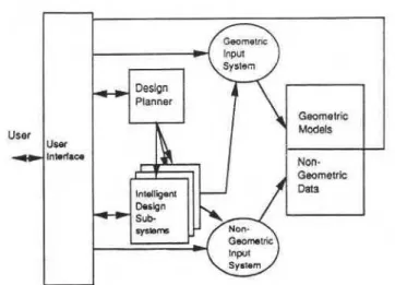
Conventional design systems allow the designer to enter graphical information using a geometric input system. This information is then transformed into a geometric model for storage and manipulation by the design system. Nongeomet- ric data, such as technical and administrative information, are entered and represented separately from geometric informa- tion. The model can be analyzed either visually, by displaying the information on adisplay, or by using specially written appli- cation software (almost entirely numerical). Initial analysis of the model is usually performed by the designer. A model of a conventional CAD system is shown in Figure 1.
A current goal of research into intelligent CAD systems is to facilitate the design process by incorporating more of the designer's knowledge and expertise into the system. To achieve this, CAD systems will require (1) more domain (application) specific knowledge, (2) symbolic as well as numeric manipu- lation, and (3) interfaces supporting geometric and design knowledge. The idea is to provide a general framework for incorporating knowledge about geometry, technical infor- mation (e.g., material properties, functional requirement specifications), and administrative requirements (standards, evolution and versions of design, related families of compo- nents, scheduling, inventory). Knowledge Contained in this general framework would be domain independent (Arbab 1987), axiomatic geometry being an example. Domain-depen- dent, or specialized, knowledge would then be incorporated
Steven M. Comick, Debbie A. Leishman, and J. Russell Thomas are Research Officers at the Advanced Construction Technology
Laboratory of the Institute for Research in Construction, National Research Council of Canada, Ottawa, ON.
THIS PREPRINT IS FOR DISCUSSION PURPOSES ONLY, FOR INCLUSION IN ASHRAE TRANSACTIONS 1990. V. 96, Pt. 2. Not to be reprinted in whole or ~n part without written permission of the American Society of Heating, Refrigerating and AirConditioning Engineers. Inc., 1791 Tullie Circle. NE, Atlanta, GA 30329.Opinlons. findings, conclusions, or recommendations expr&sed in this paper are those of the author(s) and do not necessar~ly reflect the views of ASHRAE
Figure 1 A functional view of a mechanical CAD system (Koegel1987)
into subsystems built on top of this general framework. One model of an intelligent CAD system is shown in Figure 2.
The above model differs from the model in Figure 1 in that the designer now interfaces with the CAD system through an expert design system and several intelligent design sub-
.
systems. The planner monitors the evolving design and pro- vides recommendations that guide the design activity. An intelligent design subsystem contains application-specific infor- mation appropriate to the area of design. For example, VLSl designers deal with silicon, interconnection pathways, transis- tors, etc., while architects deal with plaster, wood, and concrete. Each deals with different components, taxonomies, and design rules. Design subsystems are programs that contain fun- damental design rules (e.g., depth = spanll6, for preliminary steel design), programs that refine preliminary designs (floor layout in steel design), interfaces to knowledge bases of design examples, or programs that evaluate designs for strengths and weaknesses.A key knowledge source that should be incorporated into an intelligent building design subsystem is knowledge about build- ing regulations. The National Building Code of Canada (NBCC 1985) is an example of one such regulation. A subsystem of this type would check designs for compliance or would ensure con- formance with the regulations in an interactive fashion as the design proceeds.
BUILDING REGULATIONS What Are Building Regulations?
Building regulations are predominantly concerned with life safety and consist of a set of minimum requirements that must be met by a given building design. The requirements deal with fire protection, structural sufficiency, and public health. These three broad categories encompass such requirements as elec- trical codes (fire), plumbing codes (health), and standards (structural). A building regulation defines various components that comprise a building and supplies a set of technical require ments. These reauirements constrain the attributes of various components and'the relationships between components. The technical requirements that constitute such documents fall into one of two categories: (1) prescriptive requirements or (2) per- formance requirements.
An example of a prescriptive requirement is:
3.1.8.1 .(5) Except for closures, the required fire-resis- tance rating of every firewall shall be provided by masonry or concrete (NBCC 1985).
An example of a performance requirement is:
13.123 Connections in Combined Shear and Tension Bolts in a joint required to develop resistance to both tension and shear shall be proportioned so that the fol- lowing relationship is satisfied for the specified loads:
V /
V,
+
1.9 T/nARU<
1.0 where-
Destgn Planner Gwrnork Models Non- Geometric DamFigure 2 A model for an intelligent CAD system (Koegel1987)
V, = slip resistance as defined in Clause
13.12.2. Except that the factored ten- sion Tfshall not exceed T, given in Clause 13.11.3. (CAN3-S16.1-M78 1978.)
Requirements can be viewed as a set of constraints that must be satisfied for a design to be accepted.
Building regulations fit into a larger body of regulations that constrain almost all constructed or manufactured objects in our society. Compliance with building regulations ensures that sig- nificant details affecting health and life safety are not over- looked.
A Specific Building Regulation: The NBCC
The National Building Code of Canada (NBCC) is a model building code for Canada and specifies a set of minimum pro- visions respecting the safety of buildings with regard to public health, fire protection, and structural sufficiency. It is written in a legal form such that it can be adopted into law by any juris- dictional authority within Canada. Provincial authorities use the NBCC as the basis for their own building regulations, modify- ing it to suit specific criteria. The scope of the NBCC includes the construction, alteration, demolition, removal, or relocation of all new or existing buildings except farm buildings. The docu- ment refers to 192 other documents including other codes (such
as fire and plumbing) and standards (performance and testing). A more detailed description of the contents and structure of the NBCC is given in Cornick (1989).
Why Incorporate Building Regulations?
There are many possible intelligent subsystems that could be devised for the design of buildings. Examples include floor layout programs, programs that refine rough sketches, systems that check building regulations as the design progresses, or systems that check for conformance after a design is complete. All these systems require domain-specific knowledge, such as building regulations.
Good design practice and economic arguments suggest that building regulations be incorporated into design systems to facilitate the compliance process. A designernormally has regulations in mind when designing. However, complex regu- lations are often so complex that individual designers are not cognizant of all relevant sections and must rely on more experienced persons to check for conformance. For example, a complex building can take up to four months to undergo plan review. The incorporation of building regulations into an intel- ligent design subsystem should help to avoid the delays and costly errors that can occur when compliance checking is left until just before construction (Dym et al. 1988). Incorporating building regulations into design systems would, in effect, short-
regulations
Figure 3 Incorporatioh of knowledge in building regulations
into a design
cut the conventional way these knowledge sources are used (see Figure 3).
Incorporation Mechanisms
The first step in incorporating building regulations into design systems is to define a building reference model for the build- ing regulations. This reference model is implicit in the regula- tions and consists of (1) objects referred to by the regulation such as firewalls, beams, etc., and (2) relationships between these objects, such as: firewalls are part of a building. The regulatory aspect of regulations can then be seen as applying constraints to this model by specifying requirements for objects in the model and for relationships between these objects. For example, the fire-resistance rating of a firewall is constrained to be two hours. Thus, building regulations can be seen as con- sisting of two parts: (1) a building reference model of objects and relationships and (2) a set of constraints. The process of con- structing a building reference model consists of explicitly defin- ing the objects, relationships, and taxonomies referred to in
, regulations. Representing the regulatory aspect consists of
defining and representing the constraints that apply to the model.
Other research on standards and building regulations is con- cerned with the structure, readability, and consistency of regu- lations (Blackmore 1989; Cornick 1990). In this research, the static surface structure of the regulatory document is modeled. Their models contain, among other things, the hierarchy of sec- tions and subsections and the relationships between sections, i.e., when one section refers to another. This kind of model of building regulations is very different from the model described above.
The primary goal in this paper, unlike Blackmore(1989) and Cornick (1990), is the development of a building reference model and incorporation of this model into intelligent CAD sys- tems. This reference model is implicit within the regulationsand separate from the constraints imposed by a specific regulation such as the National Building Code of Canada.
Within a set of building regulations, there appear to be several different models, each forming part of a hierarchy. One such hierarchy is shown in Figure 4. At the lower levels of the hierarchy, there are models of the major systems within a build- ing (structural, mechanical, electrical, and plumbing systems, for example) as well as various models of use (e.g., architectural [occupancy] and fire [fire zones and smoke control]). These models all represent various parts of a building and vary con- siderably in their representation (two-dimensional models with
Structural Mechanical Plumbing Electrical Architectural Fire Model Model Model ~ o d e l Model Model
Figure 4 A building reference model contained within the National Building Code of Canada
linear elements for structures vs. three-dimensional time- dependent models with three-dimensional elements for smoke movement). All these models fit together to produce a coher- ent picture of a building (since they are, in fact, derived from one physical object). Therefore, the top-level reference models should have knowledge about the various subcomponent models and how they interact. A logical place to begin a search for a high-level model is in a building regulation whose scope covers all aspects of buildings, such as the NBCC. The authors of such a regulation must have encoded an implicit model of how all the building subsystems interact.
The building reference model shown in Figure 4 could be used to construct intelligent design subsystems in two ways. One approach would be to build an intelligent design assistant. In this type of system, constraints both administrative (building regulations) and technical would be enforced during the design process. An alternative method would be to build an automated codechecking application. Compliance checking would then occur at the end of the design cycle. Violations would be flagged and the design submitted for subsequent revision.
REVIEW OF INTEGRATED SYSTEMS
There have been several attempts to incorporate building regulations into design systems. A variety of approaches have been attempted, ranging from administrative systems to auto- mated plan checkers (Vanier 1989). This section will explore the similarities and differences of three of these approaches.
A Hypertext-Based System
The Norwegian Building Research Institute has developed a system to aid designers in designing buildings that conform to the Norwegian building regulations. The emphasis of this system has been on those sections that deal with fire require- ments (Mitusch 1988).
As a design progresses, the system determines (1) the fire classes for occupancies, (2) the fire resistance of materials, (3) the widths of escape routes, (4) the types of staircases required, (5) the division of fire sections, and (6) the need for fire alarms and other equipment. The system does not check for code compliance. Instead, it generates a set of minimum require- ments as more decisions about the design are made. A change in a design parameter is reflected in an updating of the require- ment set.
This system was developed using an object-oriented expert system shell and consists of a collection of rules and objects. Production of the system consisted of first developing a work- ing knowledge base and then transferring it to a hypertext environment. The hypertext system is considerably faster than the expert system shell because the knowledge is "hard wired" into the system (trading off flexibility). The system is also capa- ble of handling changes in design parameters as well as incor- porating interactive graphics. Explanation facilities are lacking in the hypertext implementation, although a complete report of the path through the system is generated.
An Automated Plan Checker
LSC Adviser is a prototypical knowledge-based system deve- loped at a university that reviews architectural designs for conformance with the Life Safety Code of the National Fire
Protection Association (Dym et al. 1988; Lathrop 1985). The sys- tem checks architectural floor plans against provisions for egress and fire protection in the LSC (Life Safety Code). A list of violations is generated that indicates the location and nature of the fault. The checking procedure occurs at the end of the design cycle, which requires that the design be updated and the process repeated untiM3 further violations are flagged.
In designing the system, architects and experts were inter- viewed to elicit the plan review process. A higblevel protocol that guides the automated plan checker was then developed. The LSC itself is represented as a set of "iflthen" rules cor- responding roughly to one paragraph of the LSC per rule. In addition, a knowledge base was developed using the LSC and other knowledge sources. This knowledge base contains a framebased floorplan representation that describes objects in a typical floorplan and enables reasoning about them. This floorplan representation bridges the gap between the geomet- ric models of CAD systems and the information contained in the LSC. LSC Adviser is also linked to external application pro- grams that calculate such parameters as travel distances to the nearest exit.
A Suite of Design Checkers and Assistants
The Building Research Association of New Zealand (BRANZ) has developed several buildingcodebased systems to check designs and assist designers. These systems include (1) Fire- Code (Hosking et al. 1987), a fire requirements checker; (2) Seismic (Hosking et al. 1988), a seismic requirements checker;
(3) WallBrace (Mugridge and Hosking 1988), a system that checks the wall bracing of light timber-frame buildings and offers design assistance; and (4) SubFloorBrace (Dechapunya and Whitney 1988), a system similar to WallBrace. These sys- tems were all developed using the Class language (Mugridge et al. 1987). This language, based on an object-oriented paradigm, includes features of rule-based systems and is used for solving classification problems. All the systems check pro- posed plans or offer advice to the designer based on a partic- ular document. Advice is given at the preliminary design stage and is useful for iterative design work. None of these systems is connected to a CAD system, and their inputloutput consists of character-style graphics with a textual question-and-answer session. One exception is the Seismic system, which provides input to, and interprets output from, a commercially available frame analysis program.
A Comparison
All three systems deal with small sections of the building code and mostly with fire requirements, which are generally acknowledged to be the most complex and difficult to interpret. These systems may prove difficult to extend because of their narrow scope.
The automated plan checker is distinct from the other sys- tems in that it is coupled to a CAD program. Integration of the building regulations into the CAD system required an intermedi- ate representation of the building regulations. This intermedi- ate representation forms a link between the geometric modeler and the knowledge contained in the building regulation. The designers of this system divided the intermediate representa- tion into two parts, the first being a knowledge-base represen- tation of a floorplan and the second being requirements expressed as "iflthen" rules. The programs from New Zealand and Norway are not tied to a CAD program and do not use an intermediate representation. Instead, the knowledge contained within the building regulations is incorporated directly into the application programs. Both are tailored to specific applications, which limits their extensibility.
The three systems cover a range of applications. These vary from programs that check designs for compliance at the end of the design process, much like a municipal plans examiner, to interactive design assistants that attempt to ensure confor- mance during the process of design. Plan checking appears
to be a simpler task because it is primarily static, most of the
design information being known. An interactive design assis- d
tant would involve multilevel constraint manipulation and planning.
It can be observed from this comparison that all three sys- tems use an object-oriented representation' and that interfac- ing to a generic CAD system requires a model of the particular design task. This model is necessary in order for a CAD system to have knowledge of the domain over which it is designing. For instance, design of a building requires knowledge of floors, walls, etc., whereas design of a car requires knowledge of engines, wheels, etc. The LSC Adviser described above comes closest to using a model of a building or what we have called a building reference model. It does not, however, appear to have been motivated by a desire to implement a plan checker around a building reference model. The use of a floorplan model seems to have developed out of necessity in order to interface to a real CAD system. Realizing the need for such a model, we see that the knowledge base used by the LSC Adviser is actually a par- tial building reference model, and the "if/then" rules are con- straints that apply to objects in the model and relationships between those objects. The separation of the reference model from the constraints has several advantages, namely, flexibil- ity, extendibility, and the ability to use different reasoning methods. What is needed now is a complete reference model that will allow for compliance checking of an entire building after or during a design phase.
Two significant attributes for future attempts can be derived from thepreceding examples: (1) an object-oriented approach and (2) the separation of the building reference model from the constraints in the regulations. It is these two aspects that are detailed in the next section.
BUILDING A REFERENCE MODEL: AN OBJECT-ORIENTED APPROACH Why Object Oriented?
One approach for incorporating building regulations into CAD systems is to develop an object-oriented building refer- ence model and to represent the technical requirements in the regulations as constraints. In the process of design, designers use knowledge about the objects they are designing. An object- oriented system is well adapted to represent this knowledge. As current systems focus upon the representation of geometric information, future systems must also incorporate nongeomet- ric information. Again, an object-oriented approach would be best adapted to this task. Current research into intelligent CAD systems appears to be moving in this direction.
Each of the above examples that attempted to integrate build- ing regulations into design systems used an object-oriented approach. This is primarily due to the fact that building regu- lations also deal with systems of objects. The incorporation of building regulations into design systems is facilitated by the use of a common representation. Since the implicit representation of building regulations and the representations in intelligent CAD systems are object based, an appropriate paradigm for constructing a building reference model is object oriented.
What Are Object-Oriented Systems?
I
Object-oriented programming (OOP) is based on sending messages between objects. This paradigm has three aspects:
(1) a single universal data structure (objects), (2) a uniform con- trol structure (message passing), and (3) a uniform description structure (a class hierarchy). An object is a data structure that receives messages and belongs to a class that is a part of a hierarchy of classes. Classes are defined by object behavior. Problem solving in OOP is achieved by identifying objects, mes-
sages, and objectlmessage sequences to effect a solution. A
'
Frames used in the LSC Adviser can be considered an object~riented repre- sentation.firewall fire separation construction assembly
barrier
fire-resistance ratingnoncombustibkonstruction
combustible construction noncombustible materials materials criteria combustible materials materials.criteria
1 : structural members I building assemblies building Structure - P Y building persons animals p r o m fire-resistance ratingfire
Codefm-resistance
rating material assembly flame heat criteria test performancecode
closures &vice assembly fire separation components opening m=o"v materialconcrete
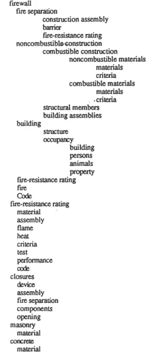
materialFigure 5 Partial list of objects derived from sample Sentence
I
-
3.1.8.1.(5) of the National Building Code of Canada system can be called object-oriented if it supports (1) abstrac- tion, (2) encapsulation, (3) inheritance, and (4) polymorphism. Abstraction is the grouping of objects with similar properties or behaviors into one class. Encapsulation of information is reflected by the fact that objects are self-contained and do not share information with other objects explicitly. These objects have distinct boundaries and a well-defined interface. Inheri- tance implies the definition of a class hierarchy containing classes, subclasses, and superclasses, where subclasses can inherit details of their superclasses. Polymorphism allows the user to send the same message to different objects and have each object respond in a way appropriate to the kind of object it is (Goldberg and Robson 1983; Pinson and Wiener 1988).An Example
The Building Reference Model As stated earlier, a build- ing code defines objects, relationships between objects, and constraints on the objects and their relationships. The building reference model consists of the objects and their relationships,
while the constraints are external to the model and represent the technical requirements for a particular regulation.
A Sentence from the NBCC The following sentence will serve as an example of how a partial building reference model can be constructed using the information contained within the NBCC. This sentence was chosen because it is relatively un- complicated and the intent is clear.
3.1.8.1 .(5) Except for closures, the required fire-resis- tance rating of every firewall shall be provided by masonry or concrete.
However, even such a simple sentence requires knowledge of a large part of the building reference model.
Building the Model The first step in defining a partial build- ing reference model is to identify all the objects contained within the sentence. (Italicized words are special terms defined by the NBCC.) There appear to be five objects contained within the sentence. They are:
firewall
fire-resistance rating closures
masonry concrete
To construct a model, all potential objects should be elabo- rated on until they can no longer be expanded. The first object selected for expansion in the list is the object firewall. The defi- nition of a firewall is given in the Code3
Firewall means a type of fire separation of noncom- bustible construction which subdivides a building or separates adjoining buildings to resist the spread of fire and which has a fire-resistance rating as prescribed in this Code and has structural stability to remain intact under fire conditions for the required fire-rated time. With the addition of the objects mentioned in this section, the list of objects now consists of:
firewall fire separation fire-resistance rating noncombustible construction building fire Code fire-resistance rating closures masonry concrete
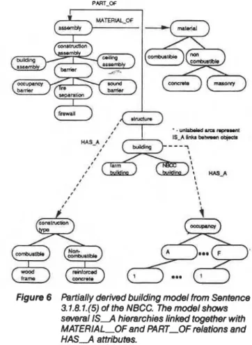
A partially expanded list of the potential objects defined by the sample sentence is shown in Figure 5. (The relevant sec- tions of the NBCC used are given in Appendix A.) This short list of objects represents some very important high-level concepts. As the list grows, the level of abstraction in the objects seems to increase with the level of nesting. High-level concepts such as building, assembly, banier, and components also appear. What relationships exist between these objects? Consider three possible relationships between objects:
1. I S J ; aspecialization (for example, a bolt is a fastener); 2. PART-OF; forms a part of (for example, a column is
part of a structure); and
3. MATERIALOF; material of object is something (for example, the material of the column is steel). Using the I S 4 relationship, it is possible to begin con- structing hierarchies of objects. The five hierarchies shown in Figure 5 are linked via the P A K O F and MATERIALOF relations and through object attributes, i.e., H A S A links (dashed lines).= In this way a building reference model begins
'Code refers to the National Building Code of Canada.
PART OF
Figure 6 Partially derived building model from Sentence 3.1.8.1.(5) of the NBCC. The model shows several I S 4 hierarchies linked together with MATERIAL-OF and PART-OF relations and H A S A attributes.
to develop from the process of making explicit the objects and their relationships, as demonstrated using this one sentence of the code.
It can be inferred from Figure 6 that a building is a structure with parts being various types of assembly. A construction assembly is a specialization of an assembly. A firewall is a specialization of a fire separation, which itself is a specializa- tion of a barrier, a type of construction assembly. The object firewall is, therefore, a part of the object structure.
Consider the two objects, fire separation and firewall. What can be said about fire separation? The class flre separation inherits the following information from its hierarchy: flre sepa- ration has a MATERIALOF relationship that relates it to the materials hierarchy and is P A C O F a building. In turn, the object fire separation is also defined by the NBCC as having a fire-resistance rating. Finally, the object firewall inherits all the information in flre separation. These objects are shown below:
fire separation I S 4 barrier
H A S 4 fire-resistance rating = undefined -
inherits
MATERIALOF = undefined P A K O F a structure
H A S 4 construction type = undefined firewall
I S 4 fire separation inherits
MATERIALOF = undefined P A W F structure
H A S A fireresistance rating = undefined locally defined
H A S A construction type = noncombustible
Constraining the Model The first example of constraining the model examines how constraints derived from the Code could be used to constrain a relationship between two objects, specifically firewall and material. Imagine the relatively sim- ple task of determining whether or not a particular firewall is constructed of appropriate materials. The definition of a firewall states that only noncombustible materials should be used. This information could be inherited along the following path: firewall P A K O F structure, structure H A S A construction type, therefore firewall H A S A construction type. The Code defines firewalls as using noncombustible construction. There
fore, in the definition of the object firewall, the attribute con-
I
struction type is constrained to be noncombustible. In order Ito check or enforce this constraint, a predicate can be written 1
to construct a list of materials using the MATERIALOF rela- A
/
tionship. Since each material in that list is part of the materials hierarchy, the predicate would check the I S A relationship for each material chosen. If one of the materials chosen does not match the construction type, then the predicate would return false, indicating a violation. Otherwise, a value of true would be returned, meaning the design conforms. The predicate could be written as follows:
checkmaterial(assemb1y)
if <any material in MATERlALOF(assemb1y) doesn't match construction type(assembly)> then flag violation
else ok
Thus, if a message checkmaterial(instance-of-firewall) is sent to a firewall object, all the materials listed by the MATERIALOF relationship will be checked against the value of construction type to make sure no combustible materials are on the list.
The NBCC contains even more specific information about firewalls. The example sentence further restricts the materials used in firewalls to concrete or masonry. The definition of fire- walls simply states that they should be made of materials that do not burn. Thus, as one descends the assembly I S 4 hier- archy, there are no restrictions on the type of materials; however, as soon as a specialization is made from a fire sepa- ration to firewall, the constraints construction type(firewal1) = noncombustible and MATERlALOF(firewa1l) = (masonry OR concrete) are applied.
A second example involves constraining an attribute of an object. Sentences 3.1.8.1.(3) and (4) of the NBCC (see Appen- dix A) constrain the value of the attribute fire-resistance rating to two or four hours. The firewall object with the constraints applied is shown below.
firewall
I S 4 fire separation inherits
MATERIALOF = (concrete OR masonry)
P A K O F structure
1
I
locally defined
H A S A fire-resistance rating = (2 OR 4 hours)
H A S A construction type = noncom- bustible
When a designer creates an instance of firewall, the exter- nal constraints would be imposed, thus adding information to a newly created object. Changing the constraints has no effect on the definition of the object. For example, if the authors of the NBCC decided to extend the list of allowable materials for fire- walls, only the constraint on the MATERIALOF relationship need be changed (provided the added materials already exist in the hierarchy). This illustrates the advantage of separating the building reference model from the requirements in a build- ing regulation.
CONCLUSIONS
To enable building designers to design effectively using com- puters, knowledge about building regulations must be included in CAD systems. Models of buildings are encoded implicitly into building regulations and, therefore, a considerable amount of work needs to be carri&but on the representation of these regulations. In order to incorporate building regulations into CAD systems, one or several building reference models implicit in building regulations must be explicated in order to couple nongeometric information with geometric modelers. Linking the geometric objects of a CAD system to the objects of a building reference model would embody the objects with the technical and administrative knowledge required for intelligent design. A flexible approach involves the separation of the building refer- ence model, that is, objects and the relationships between objects, from the technical requirements or constraints prescribed by the regulation. An appropriate approach for con- structing building reference models and integrating them into intelligent CAD systems is to develop these models using an object-oriented paradigm. It should be noted that what has been demonstrated in this paper is only the first step toward con- structing a complete building reference model.
REFERENCES
Arbab, F. 1987. "A paradigm for intelligent CAD." In: I? Hagen and T. Tomiyama (eds.), lntelligent CAD systems I: Theo- retical and Methodological Aspects, pp. 20-39. Berlin: Springer-Verlag.
Blackmore, J.M. 1989. "The development of the Building Code of Australia, the project management of a complex code." In: Proceedings of the International Conference on Municipal Code Administration Building Safety and the Computer; pp. 27-42. Winnipeg, Manitoba, Canada, 24-28 September, Manitoba Building Officials Associations Inc.
Brown, D.C., and B. Chandrasekaran. 1985. "Expert systems for a class of design activity." In: J.S. Gero, ed., Proceedings of the lFlP WG5.2 Working Conference on Knowledge Engineering in Computer-Aided Design, pp. 258-282. Buda- pest, Hungary, 17-19 September 1984. Amsterdam: North Holland.
CAN3-S16.1-M78. 1978. Steel structures for buildings-limit states design. Rexdale, Ontario: Canadian Standards Association.
Cornick, S.M. 1990. "HyperCode: The building code as a hyper- document." Submitted to Engineering with Computers: An International Journal for Computer-Aided Mechanical and Structural Engineering.
Dechapunya, A.H., and R.S. Whitney. 1988. "Knowledge-based systems for building technology in New Zealand." Reprint No. 83. Reprinted from the Proceedings of Symposium on Knowledge-based Systems in Civil Engineering, August, Monash University, Clayton. Porirua, New Zealand: Build- ing Research Association of New Zealand.
Dym, C.L.; R.P. Henchy; E.A. Felis; and S. Gonick. 1988. "A knowledge-based system for automated architectural code checking." Computer-Aided Design, Vol. 20, No. 3, April, pp. 137-1 45.
Goldberg, A., and D. Robson. 1983. Smalltalk-80, the language and its implementation. Reading, MA: Addison Wesley. Hosking, J.G.; W.B. Mugridge; and M. Buis. 1987. "Expertsys-
terns for regulations and codes." Reprint No. 66. Reprinted from Proceedings
of
the Second New Zealand Conference on Expert Systems, 2-4 February, Auckland, N.Z. Porirua, New Zealand: Building Research Association of New Zealand. Hosking, J.G.; S. Lomas; W.B. Mugridge; and A.J. Cranston. 1988. "The development of an expert system for seismic loading." Reprint No. 84. Reprinted from the Proceedings of Symposium on Knowledge-based Systems in Civil Engineer- ing, August, Monash University, Clayton. Porirua, New Zealand: Building Research Association of New Zealand.Koegel, J.F. 1987.
1
theoretical model for intelligent CAD." In: I? Hagen and T. Tomiyama, eds., Intelligent CAD Systems I: Theoretical and Methodological Aspects, pp. 206-223. Berlin: Springer-Verlag.Lathrop, J.K. (ed). 1985. Life safetycode handbook, 3d ed. Wor-
cester, MA: National Fire Protection Association.
Mitusch, PD. 1988. Expert system for the Norwegian building regulations-a new approach. Oslo, Norway: Norwegian Building Research Institute.
Mugridge, W.B., and J.G. Hosking. 1988. "The development of an expert system for wall bracing design." Reprint No. 73. Reprinted from Proceedings of the Third New Zealand Con- ference on Expert Systems, 11-13 May, Wellington N.Z. Porirua, New Zealand: Building Research Association of New Zealand.
NBCC. 1985. The National building code of Canada, 9t h ed. Ottawa, Ontario: Associate Committee on the National Building Code, National Research Council of Canada. Pinson, L., and R. Wiener. 1988. An introduction'to object-ori-
entedprogramming, Smalltalk. New York: Addison Wesley. Vanier, D.J. 1989. "Computerization of building regulations." In Proceedings of the International Conference on Municipal Code Administration Building Safety and the compute^ Win- nipeg, Manitoba, Canada, 24-28 September, Manitoba Building Officials Associations, Inc. (pp. 43-62).
APPENDIX A
EXCERPTS FROM THE NBCC USED TO CONSTRUCT THE PARTIAL BUILDING REFERENCE MODEL
Building means any structure used or intended for support- ing or sheltering any use or occupancy.
Closure means a device or assembly for closing an opening through a fire separation, such as a door, a shutter, wired glass or glass block, and includes all components such as hardware, closing devices, frames and anchors.
Combustible means that a material fails to meet the accep- tance criteria of CAN4-S114, "Standard Method of Test for Determination of Non-Combustibility in Building Materials."
Combustible construction means that type of construction that does not meet the requirements for noncombustible con- struction.
Fire-resistance rating means the time in hours or fraction thereof that a material or assembly of materials will withstand the passage of flame and the transmission of heat when exposed to fire under specified conditions of test and perfor- mance criteria, or as determined by extension or interpretation of information derived therefrom as prescribed in this Code.
Fire separation means a construction assembly that acts as a barrier against the spread of fire. (See Appendix A.)
Firewall means a type of fire separation of noncombustible construction, which subdivides a building or separates adjoin- ing buildings to resist the spread of fire and which has a fire- resistance rating as prescribed in this Code and has structure stability to remain intact under fire conditions for the required fire-rated time.
Noncombustible means that a material meets the accep- tance criteria of CAN4-S114, "Standard Method of Test for Determination of Non-Combustibility in Building Materials."
Noncombustible construction means that type of construc- tion in which a degree of fire safety is attained by the use of non- combustible materials for structural members and other building assemblies.
Occupancy means the use or intended use of a building or part thereof for the shelter or support of persons, animals, or property.
(3) Every required firewall which separates a building or buildings with floor areas containing a Group E or a Group F,
Division 1 or 2 major occupancy shall be constructed as a fire separation of noncombustible construction having a fire-
I
resistance rating of at least 4 h, except that where the upper por- Group E or Group F, Division 1 or 2 shdl be constructed as a c
tion of a firewall separates floor areas containing other than fire separation of noncombustible construction having a fire- Group E or Group F, Division 1 or 2 major occupancies, the fire- resistance rating of at least 2 h.
resistance rating of the upper portion of the firewall may be (5) Except for closures, the required fire-resistance rating of reduced to 2 h. every firewall shall be provided by masonry or concrete.
(4) Every required f i m m n i c h separates a building or build- A-1.3.2.