Publisher’s version / Version de l'éditeur:
Vous avez des questions? Nous pouvons vous aider. Pour communiquer directement avec un auteur, consultez la
première page de la revue dans laquelle son article a été publié afin de trouver ses coordonnées. Si vous n’arrivez pas à les repérer, communiquez avec nous à PublicationsArchive-ArchivesPublications@nrc-cnrc.gc.ca.
Questions? Contact the NRC Publications Archive team at
PublicationsArchive-ArchivesPublications@nrc-cnrc.gc.ca. If you wish to email the authors directly, please see the first page of the publication for their contact information.
https://publications-cnrc.canada.ca/fra/droits
L’accès à ce site Web et l’utilisation de son contenu sont assujettis aux conditions présentées dans le site LISEZ CES CONDITIONS ATTENTIVEMENT AVANT D’UTILISER CE SITE WEB.
Student Report (National Research Council of Canada. Institute for Ocean Technology); no. SR-2005-16, 2005
READ THESE TERMS AND CONDITIONS CAREFULLY BEFORE USING THIS WEBSITE.
https://nrc-publications.canada.ca/eng/copyright
NRC Publications Archive Record / Notice des Archives des publications du CNRC :
https://nrc-publications.canada.ca/eng/view/object/?id=a9260b87-0f6c-470d-bea2-446be292ecae https://publications-cnrc.canada.ca/fra/voir/objet/?id=a9260b87-0f6c-470d-bea2-446be292ecae
NRC Publications Archive
Archives des publications du CNRC
For the publisher’s version, please access the DOI link below./ Pour consulter la version de l’éditeur, utilisez le lien DOI ci-dessous.
https://doi.org/10.4224/8895145
Access and use of this website and the material on it are subject to the Terms and Conditions set forth at Trim, ballast and battery systems in a buoyancy engine for an underwater glider
REPORT NUMBER SR-2005-16 NRC REPORT NUMBER --- DATE August 2005
REPORT SECURITY CLASSIFICATION Unclassified
DISTRIBUTION Unlimited TITLE
TRIM, BALLAST AND BATTERY SYSTEMS IN A BUOYANCY ENGINE FOR AN UNDERWATER GLIDER
AUTHOR(S) Steven Williams
CORPORATE AUTHOR(S)/PERFORMING AGENCY(S)
National Research Council, Institute for Ocean Technology (NRC-IOT) PUBLICATION
---
SPONSORING AGENCY(S)
National Research Council, Institute for Ocean Technology (NRC-IOT) IMD PROJECT NUMBER
42_2088_10
NRC FILE NUMBER ---
KEY WORDS
buoyancy engine, BE, underwater glider, autonomous underwater vehicle, AUV
PAGES vii, 25, App. A-C FIGS. 18 TABLES 2 SUMMARY:
This report details the study into trimming and ballasting the buoyancy engine designed by NRC-IOT. The introduction discusses the basics of a glider, as well as current gliders already in operation around the world. Design considerations are then listed and their effects on the glider noted. The design of a nosepiece and tether cable prior to testing is described. The locations of the center of mass and center of buoyancy are calculated, are related to one another, and are discussed. Section 4 includes the implementation of a system of lead weights to test the buoyancy engine’s ability to position itself horizontally and to rise and fall at
acceptable glide angles. Section 5 details the concept selection of battery type, size, shape, weight, and other factors. MATLAB code for communicating with the serial data
communicationsport is discussed and results of tests are given. Future work is then discussed along with a conclusion.
ADDRESS: National Research Council Institute for Ocean Technology Arctic Avenue, P. O. Box 12093 St. John's, NL A1B 3T5
National Research Council Conseil national de recherches Canada Canada
Institute for Ocean Institut de technologies Technology océaniques
TRIM, BALLAST AND BATTERY SYSTEMS IN A BUOYANCY ENGINE FOR
AN UNDERWATER GLIDER
SR-2005-16
Steven Williams
SUMMARY
This report details the study into trimming and ballasting the buoyancy engine designed by NRC-IOT. The introduction discusses the basics of a glider, as well as current gliders already in operation around the world. Design considerations are then listed and their effects on the glider noted. The design of a nosepiece and tether cable prior to testing is described. The locations of the center of mass and center of buoyancy are calculated, are related to one another, and are discussed. Section 4 includes the implementation of a system of lead weights to test the buoyancy engine’s ability to position itself horizontally and to rise and fall at acceptable glide angles. MATLAB code for communicating with the serial data communicationsport is discussed and results of tests are given. Finally, section 5 details the concept selection of battery type, size, shape, weight, and other factors. Future work is then discussed along with a conclusion.
TABLE OF CONTENTS
1.0 INTRODUCTION 1
2.0 DESIGN CHALLENGE 3
2.1 Design Issues 3
3.0 MODIFICATIONS PRIOR TO TESTING 4
3.1 Nose Piece 4
3.2 Tether Cable 5
4.0 CENTER OF MASS AND CENTER OF BUOYANCY 7
4.1 Center of Mass Calculations 7
4.2 Center of Buoyancy Calculations 8
4.3 Relationship Between the COM and COB 9
5.0 BATTERY SYSTEM 12 5.1 Design Constraints 12 5.2 Battery Comparison 12 5.3 Analysis 18 6.0 MATLAB CODE 20 6.1 Communications 20 6.2 Controllers 20
7.0 CONCLUSIONS AND RECOMMENDATIONS 23
REFERENCES 24
APPENDIX A – CAD DRAWINGS APPENDIX B – MATLAB CODE
LIST OF TABLES
Table 1: COM of Buoyancy Engine 8
LIST OF FIGURES
Figure 1: Seaglider’s method of movement through water 1
Figure 2: Spray glider cross section 2
Figure 3: Nosepiece for BE 4
Figure 4: Tether Cable with Styrofoam for Neutral Buoyancy 6
Figure 5: Finding COM of the Buoyancy Engine 7
Figure 6: Position of COB as a result of diaphragm movement 9
Figure 7: COM and COB relationship 9
Figure 8: Change in COM and COB due to Moving Diaphragm 10 Figure 9: Horizontal position of Buoyancy Engine in the Trim Tank 11
Figure 10: Scale cross section of the BE 13
Figure 11: Packing Factor Inside Both Sections of the Buoyancy Engine 14 Figure 12 Battery Power in Electronics Section of BE 15
Figure 13: Power in the Motor Section of BE 16
Figure 14 Total Power of Battery System 16
Figure 15: Power due to maximum batteries for neutral buoyancy 17
Figure 16: Emoli Battery Layout 18
Figure 17: Depth and Position Using “if else” Controller 21 Figure 18: Depth and Position using PD controller 22
LIST OF ABBREVIATIONS AND SYMBOLS
AUV………Autonomous Underwater Vehicle ABS……….Acrylonitrile Butadiene Styrene GPS……….Global Positioning System
NRC-IOT………National Research Council Institute for Ocean Technology PVC………Polyvinyl Chloride
GUI……….Graphical User Interface COM………...Center of Mass
COB………Center of Buoyancy BE………..…….Buoyancy Engine
1.0 INTRODUCTION
AUVs, or Autonomous Underwater Vehicles are a new form of sub-sea technology emerging in today’s race to explore one of the last mysteries left on earth, the Ocean. An AUV is simply a vessel that can explore water bodies without any direct human intervention. The AUV is given a preprogrammed path and then uses a combination of sensors and access to the GPS system in order to navigate. Recently, a new breed of the AUV has been developed and classed as an underwater glider.
The underwater glider is a very energy-efficient vessel that can operate without human contact for months at a time. It does this through the use of a buoyancy engine. This engine simply changes the volume inside the AUV to make it rise and fall in the water. It uses a small sliding mass to control its pitch attitude and moves forward using the lift force created on its wings.
Figure 1: Seaglider’s method of movement through water
The Seaglider is an underwater glider developed at the University of Washington and includes a very streamlined hull that matches the compressibility of water. In figure 1 you can see how it uses the upward and downward motions to move forward in the water. The antennae located on the back also permits it to connect to the GPS system when it surfaces, as well as receive and send instructions and data.
Besides the Seaglider, there are other gliders currently in use around the world. These include the Spray Glider developed by the Scripps Institution of Oceanography, and the Slocum Glider by Webb Research. The Slocum Glider has recently developed a thermal engine that permits it to carry out a mission for up to five years. It uses the temperature differences in the ocean as an energy source, which truly shows the advantages of the glider over other underwater research vessels. The Spray Glider is best know as the first glider to cross the Gulf Stream, moving at about 12 miles a day.
Figure 2: Spray glider cross section
Figure 2 shows the movement system in the Spray Glider as mentioned earlier. It uses a system of two bladders to change the volume located inside the hull. Its pitch and roll is controlled using two separate packs of moveable batteries.
2.0 DESIGN CHALLENGE
It is the goal of NRC-CNRC to produce a working Buoyancy Engine (BE) as a Test Platform for a flexible fin currently under development. This fin is made with rubber material capable of twisting its shape in order to control the BE’s position and direction of motion. The BE uses a linear actuator and diaphragm to change its internal volume. Currently, it is operating using a tether cable connected to two 24V sources and the serial port. It also floats in a vertical position without pitch control.
In this phase of development, battery systems must be analyzed and concepts studied. Also, pitch control needs to be developed and the center of mass (COM) and center of buoyancy (COB) studied. As well, MATLAB code must be written that can collect the data from the serial port and plot instantaneously, leading to GUI development.
2.1 Design Issues
Weight – The BE cannot weigh more than its buoyant force including the mass of the batteries and the battery tray.
Batteries – The battery system needs to contain sufficient energy to power the BE and not create negative buoyancy. The batteries must fit into the BE without hindering any other aspect of the engine. Enough batteries must fit so that two 24V sources can be created. The batteries need to operate for at least one hour (average test time) without recharge.
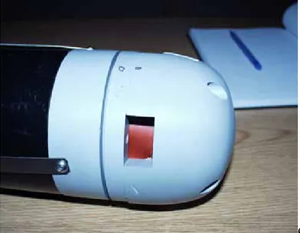
Diaphragm – As the diaphragm extends past the end of the BE, it needs to be protected against collisions that could possibly damage and tear the rubber.
Pitch – When the piston moves, the locations of the COM and COB move. This can create a moment that will change the pitch attitude of the vehicle. This change needs to be controlled so that it can be used to an advantage. i.e. when BE increases its volume, the nose points upward and vice versa.
Tether Cable – The cable must be made neutrally buoyant in order to minimize the effects of its added mass on the end of the BE. Although this was not a big issue for the vertical testing, when the BE is placed horizontally, it will have a great impact on the validity of the data collected from the sensors.
3.0 MODIFICATIONS PRIOR TO TESTING 3.1 Nose Piece
As a result of the diaphragm being exposed, a nosepiece needed to be fabricated to protect the end of the Buoyancy Engine. Initially, a wire mesh was going to be used that would fit onto the nose via the holes in the end cap used during installation.
However, this would add a lot of extra mass to the front end of the BE which was very undesirable.
After concept selection, it was decided to fabricate the nose cone out of PVC that was left over from previous work. The PVC was then taken prior to machining and its volume and mass found. Its shape (cylindrical) allowed easy calculation of volume and mass and as a result, density (density = mass/volume). The density of the PVC was found to be 1.438 g/cm³.
Figure 3: Nosepiece for BE
From the density the volume of the nose cap was determined: Volume = Mass of Cap / Density of material
V = 549 g / 1.4378 cm/g³ V = 381.9 cm³
If the density of water is 1g /cm³ fresh water:
The added mass to the BE in water is 381.9 g and therefore must be included in the mass in water of the system.
It was also decided that the nose would be held in place via four screws therefore new holes had to be drilled into the end cap. These screws in total weigh 55.3 g and must also be included in the mass of the BE.
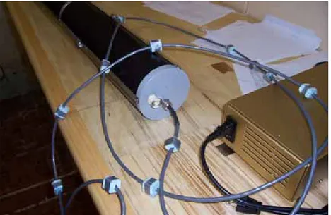
3.2 Tether Cable
The cable needed to be made neutrally buoyant so it would not hinder the vehicle during test.
At 10 meters long and 466 grams, it was decided the best way to do this was with Styrofoam placed at specific intervals along the cable.
At 1 g/cm³ in fresh water, the volume of the cable is equal to its mass in water Assuming the cable is a cylinder,
V = pi * r² * h
where r = radius (cm) and h = length of cable (cm) V = (3.14159) (0.28)² (1066.8)
V = 262.8 cc
Therefore, for neutral buoyancy: 466 g – 262.8 g = 203.2g
203.2 g must be removed from the cable.
This can be achieved using the buoyant effects of the Styrofoam. However first the density of the foam had to be found. Using the density equation, it was found to be 0.0587 g/cm³.
To find the total volume and mass of Styrofoam needed: Eq (1) density of foam = mass / volume
Eq (2) volume (1 cc = 1 g) – mass = 203.2 g therefore:
Volume = 215.87 cc Mass = 12.67 g
If a foam block is placed every 30 cm, 35 blocks would be needed, therefore the volume of each block must be 6.17 cc.
If blocks have a height of 2 cm and a hole for the cable: 6.17 cc = (L) * (L) * (H) – (0.28)²(pi)(H)
where: L = length and width of block H = height of block = 2 cm 6.17 = L² * (2) – 0.2375 * (2) L = 1.82 cm
It was then decided to cut these blocks in half in order to easily install them onto the cable. A small piece of tape was used to hold them together which does not significantly affect the buoyancy of the cable.
4.0 CENTER OF MASS AND CENTER OF BUOYANCY 4.1 Center of Mass Calculations
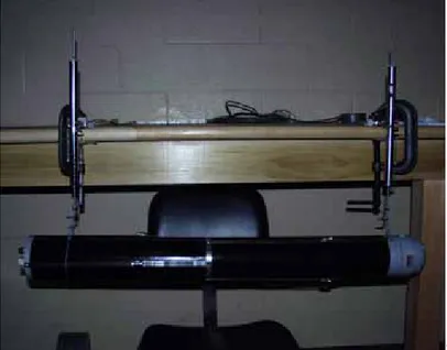
The location of the center of mass of the BE is one of the major factors affecting the attitude of the BE. The COM must line up with the COB in order for the BE to maintain horizontal positioning. As the body is non-uniform it is very difficult to calculate the exact position of the COM. Experimentally, it can be found by hanging the Buoyancy engine from linear hanging scales and taking the mass readings as well as their position to a datum point on the BE.A MATLAB code was written to determine the center of mass (with and without batteries).
Figure 5: Finding COM of the Buoyancy Engine
The center of mass can be found using the following: x_c = (m_1*x_1 + m_2*x_2)/(m_1 + m_2)
where:
x_c = center of mass
m_1 and m_2 = readings on scales 1 and 2 respectively x_1 and x_2 = distances to scales 1 and 2 respectively
Initially, we wanted to find the COM without any added mass inside the hull. A series of test were performed and the average of the test taken as the experimental center of mass:
Test # Mass Scale 1 (kg) Mass scale 2 (kg) Distance to scale 1 (cm) Distance to scale 2 (cm) Center of Mass (cm) 1 4.72 3.52 33 92.5 58.41 2 2.5 6.15 15 74.5 57.30 3 4.32 3.78 23 97.5 57.77 4 4 4.32 24 89.2 57.78
Ave COM = 57.8 cm from electronics end cap
Table 1: COM of Buoyancy Engine
This value agreed with the rough measurement of 57.5 cm taken by placing the BE on a wedge.
4.2 Center of Buoyancy Calculations
The buoyant force is the upward force on the engine as a result of the volume of water it displaces. The COB is located at the geometric center of the displaced volume. Since the BE is composed of two simple shapes, the volume and center of both the end cap and hull can easily be calculated.
The cap was divided into two sections, the circular top and the legs. The hull was then divided into the outside cylinder, and the moveable inside cylinder (diaphragm). The COB was then found by adding up the volumes of each section and the product of their individual centers and volumes. Summing these products and dividing by the total volume gives the location of center of buoyancy.
The equation is as follows:
x = [ (x1 * V1) + (x2 * V2) + (xn * Vn)… ] / V where x = center of mass overall
V = total volume overall
Xn = center of mass of each section Vn = Volume of each section
A MATLAB code was written and it was found that when the piston was in the neutral position, the COB was located at 51.25 cm from the electronics end cap.
The following graph shows the position of the COB when the diaphragm moves away from the neutral position:
Figure 6: Position of COB as a result of diaphragm movement
4.3 Relationship Between the COM and COB
The COM and COB are closely related in controlling the pitch and roll attitude of the device. When they are located at different points in the BE, there is a moment created that will cause the BE to change its pitch attitude. This can be seen in the following diagram:
The COM is located in the bottom of the engine for stability reasons. When the COB is located in front of the COM, the engine will tip upward. This is a direct result of their distance apart (d) and height difference (h).
The angle that the BE will tip can be determined easily when the ‘d’ and ‘h’ values are known. It is:
θ = 90 – ( tan¯¹ (h/d) )
where θ is the angle of the BE relative to the horizontal axis.
Using MATLAB, a program was written to determine the change in the positions of the COM and COB as a result of the piston movement (assuming that in the neutral position, the battery mass would allow the COM and COB to line up). The following results were obtained:
Figure 8: Change in COM and COB due to Moving Diaphragm
From this graph it can be seen that the COB is located at about 51.25 cm when the piston is in the neutral position. Also, the COB changes by about 1.24 cm when the piston moves 7 cm.
After performing a second series of linear hanging scale tests, it was found that by
moving the piston while the BE was hanging by the scales, the center of mass changed by 0.8 cm with a piston movement of 7 cm.
This situation will allow the COB to be located behind the COM when the piston is in an aft ward position and vice versa when the piston is in a forward position. As a result the nose will point down when the BE is diving, and up when the BE is surfacing.
The center of mass should be able to be changed by a moving battery tray that can shift the internal weight of the batteries towards the nose of the AUV. Until a battery system and layout are decided on, the exact changes in the center of mass cannot be calculated. (Battery systems are discussed in a separate section of the report).
The mathematical model was then tested though a variety of test conditions in the Trim Tank. Lead masses were used in place of the battery system. The MATLAB code was used in order to find the proper locations of the lead masses in order to achieve a level attitude in the neutral position.
Lead masses of 1.6 kg and 0.28 kg were placed at 31.5 cm and 5 cm respectively from the end cap. Also, a mass of 0.39 kg was taped to the outside of the nose cone (107.5 cm). With this setup, the BE was horizontal and neutral when the piston was moved –1.8 (aft ward) from its starting position. This small positive buoyancy is desirable in case of malfunction. The engine’s nosepiece did float up on ascent as expected. On descent, the engine moved down horizontally, indicating that with a small movement of batteries, this can be changed so that the nosepiece points downward.
5.0 BATTERY SYSTEM
In designing a battery system for the AUV, there are many limits and restrictions that must all be incorporated into the final design. As all the constraints affect one another, it is difficult to find a system that will work.
We ultimately would like to design a battery system that uses two separate 24 V battery packs; one that will power the electronics and one to power the motor. According to Chris Warren’s specification sheets [5], the motor will draw approximately 5 Amps and the electronics will draw 83 milliamps. For testing purposes, we would like to see the battery system last for at least an hour, as most testing will not take longer than this. Some of the constraints we have to be concerned about are:
Type – Different battery compositions offer unique advantages. For example, Lithium ion batteries can be recharged, hold current well, and can tolerate higher current draw. However, they are costly, affected by temperature, and react violently with water. Alkaline batteries typically have a high current rating, and great lifetime, however, cannot be recharged.
Physical space – As the ABS pipe is only 10 cm in diameter and one metre long, there is not much physical space for batteries. Once the piston and electronics are in place, the amount of usable space is greatly decreased.
Shape – As a result of the space limitations, only certain shapes and sizes of batteries will fit into the BE, greatly reducing our selection.
Weight – The total weight of the BE must be equal to its volume in order to achieve neutral buoyancy. This means that a total mass of about 2.19 kg can be added in batteries and their mounting mechanisms.
The battery packs must be designed so that enough batteries can be connected together to make two 24 V sources with a high enough capacity as to be able to power the system for an hour.
Initially, I began to look at typical C and D cell alkaline batteries. Also, two different types of Li-ion batteries were researched. The first was a rectangular model made by Saft Batteries. These batteries are part of the MP series and come in three different sizes. The second was a cylindrical battery made by Moli Energy.
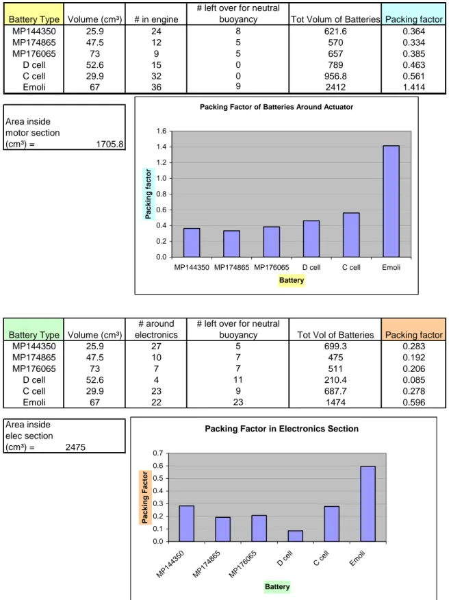
The shape of the batteries greatly affect how the system must be laid out for maximum packing efficiency. For this reason an AutoCAD model of the engine was constructed that would allow for scale models of batteries to be virtually placed in the engine.
The first design constraint considered was size. For this, the packing factor inside the BE was found by calculating the approximate internal volume of the electronics section and the motor section separately. A model of each battery was then placed into the
AutoCAD model (see figure 10). The number of batteries that would fit into each section was determined as well as how many would have to be placed in the other section to achieve neutral buoyancy. The best battery layout, weight, and power were not involved in these initial calculations.
Battery Type Volume (cm³) # in engine
# left over for neutral
buoyancy Tot Volum of Batteries Packing factor
MP144350 25.9 24 8 621.6 0.364 MP174865 47.5 12 5 570 0.334 MP176065 73 9 5 657 0.385 D cell 52.6 15 0 789 0.463 C cell 29.9 32 0 956.8 0.561 Emoli 67 36 9 2412 1.414 Area inside motor section (cm³) = 1705.8
Battery Type Volume (cm³)
# around electronics
# left over for neutral
buoyancy Tot Vol of Batteries Packing factor
MP144350 25.9 27 5 699.3 0.283 MP174865 47.5 10 7 475 0.192 MP176065 73 7 7 511 0.206 D cell 52.6 4 11 210.4 0.085 C cell 29.9 23 9 687.7 0.278 Emoli 67 22 23 1474 0.596 Area inside elec section (cm³) = 2475
Packing Factor of Batteries Around Actuator
0.0 0.2 0.4 0.6 0.8 1.0 1.2 1.4 1.6
MP144350 MP174865 MP176065 D cell C cell Emoli
Battery
Packing factor
Packing Factor in Electronics Section
0.0 0.1 0.2 0.3 0.4 0.5 0.6 0.7 MP 144 350 MP 17486 5 MP 1760 65 D cell C c ell Em oli Battery Packing Factor
From these results, it can be seen that the smaller sized batteries, as expected, generated the largest packing factor, particularly the Emoli batteries, which are about the same diameter as an AA battery. It can easily be seen that the D cell and the two largest of the MP series are not well suited to the application in regards to their size.
The next component looked at was the power output by each cell. The total power was calculated for each cell assuming a one-hour test time. As the electronics section and motor section use separate power sources, the power for each section was calculated separately and then added together. This can be seen in the following data sheet:
Battery System for Electronics Section of BE
* calculations assuming a1 hour test time Battery Type # around sensor # under circuit
Voltage (V) Ah current (Amps) Power of 1 batt (Watt) Power tot (Watt) MP144350 7 7 3.6 2.3 2.3 8.28 115.92 MP174865 3 3 3.6 4.6 4.6 16.56 99.36 MP176065 2 2 3.75 6.1 6.1 22.875 91.5 C 7 6 1.5 6 6 9 1 D 0 4 1.5 12 12 18 72 Emoli 12 10 3.75 2.4 2.4 9 198 17
Max Power from Battery System
0 50 100 150 200 250 MP144350 MP174865 MP176065 C D Emoli Battery Type
Power Tot (Watt)
Battery System for M otor Section of BE *asum ing 1 hour test tim e
Battery T ype # around actuator
Voltage (V) Ah Current (Am ps) Power of 1 batt (W att) Power tot (W att) M P144350 24 3.6 2.3 2.3 8.3 198.7 M P174865 12 3.6 4.6 4.6 16.6 198.7 M P176065 9 3.75 6.1 6.1 22.9 205.9 C 32 1.5 6 6 9 D 15 1.5 12 12 18 270 Em oli 36 3.75 2.4 2.4 9 324 288
M ax Pow er from M otor Battery System
0 50 100 150 200 250 300 350 M P144350 M P174865 M P176065 C D Em oli Battery Type Po wer T o t (Watt)
Figure 13: Power in the Motor Section of BE
Total Power from Each Battery Type
Battery Type Total Batteries
Batt needed for
neutral buoyancy Power in actuator Power in Elecronics Total Power
MP144350 38 32 198.7 115.9 314.6 MP174865 18 17 198.7 99.4 298.1 MP176065 13 14 205.9 91.5 297.4 C 45 32 288 117 405 D 19 15 270 72 342 Emoli 58 45 324 198 522 Total Power 0 100 200 300 400 500 600 MP 144350 MP 174865 MP 176065 C D Em oli Battery type Power
(watts) Electronics Power
Actuator Power
From these data it was easily seen that the Emoli batteries would perform best, followed by the C cell battery. As the alkaline battery cannot be recharged, it is not an ideal solution. The MP Series batteries were very close in performance, however the smaller model produces the most power as a result of a higher battery concentration in the BE. Another factor that had to be looked at was the total weight of the system.
The weight of each battery was calculated, and the maximum number of batteries for neutral buoyancy recorded. From this, another chart was made up comparing the cells:
Power for max Batteries due to Neutral Buoyancy Battery Type Total Batteries**
Batt Needed for Neutral Buoyancy
Power of 1
battery Total Power
MP144350 32 32 8.28 264.96 MP174865 17 17 16.56 281.52 MP176065 13 14 22.875 297.375 C 32 32 9 288 D 15 15 18 270 Emoli 45 45 9 405
** For this graph, the battery total is limited by the amount allowed for neutral bouyancy.
0 50 100 150 200 250 300 350 400 450 MP144350 MP174865 MP176065 C D Emoli Battery Type Pow e r
Figure 15: Power due to max batteries for neutral buoyancy
After analyzing the graphs, it was easy to see that the smaller batteries ultimately preformed well. Also, a few of the batteries could be completely ruled out:
a. The D cell battery would not fit into the electronics section, and with a battery tray would not fit into the motor section either.
b. The MP 176065 had problems in that a 24 V source could not be created with the batteries in the electronics section without having to use batteries from the motor section. This would hinder the sliding battery tray and add more weight to the nose.
The COM and COB of the best battery systems were then examined. AutoCAD models of the MP 174865 and the Emoli cells positioning in the BE were built. These positions were then used in the COM MATLAB program.
Ideally, the COM and COB should sit 51.25 cm from the electronics end cap when the piston is in the neutral position. Using the MP series, it was found that without adding extra weight or floats, the COM could not be moved behind the COB.
Using the Emoli batteries, it is possible to place both the COB and COM at 51.25 cm (see AutoCAD appendix). When the piston moves to +7cm (forward) , the COB moves to 52.5 and COM to 51.3. This will create a moment that will turn the BE upward which is desirable. If the batteries around the actuator are then slid forward, when the piston moves to – 7 cm (aft ward), the COB moves to 50.14 and the COM to 52.87. This would allow the BE to dive nose down at an angle dependant on the positioning of the batteries.
Figure 16: Emoli Battery Layout
From the above, it can be seen that the Emoli batteries are best suited to the application. As Emoli Canada will usually only sell direct to battery pack manufactures and the like, it may be difficult to obtain the cells. However, after searching for similar shaped batteries, a model from www.batteryspace.com, the ICR18650 was found with the same
dimensions.
Battery Type Cost per unit $ Amount Needed Total Cost $
MP 144350 44.50 CAD 32 1424 CAD
MP 174865 62.50 CAD 17 1062.50 CAD
MP 176065 76.20 CAD 13 990.60 CAD
Emoli 18650J 4.00 US 32 128 US
Emoli 26700 15.00 US n/a n/a
Battery Space 18650 5.00 US 32 160 US
As can be seen in this table, the MP series are very expensive and do not provide a power advantage. However, they do perform better in lower temperatures and for this reason could be considered in a final product. Some modifications of the internal layout and size would also be required.
For this engine, the industrial Li-Ion batteries from Emoli and Battery Space would provide the best price to performance ratio.
A few things to consider in the future about the battery system:
The current drawn by the motor depends on its depth. This is a result of the increased pressure pushing against the piston. A current probe is needed to determine the amount of power the motor will draw.
The maximum discharge rate of the battery cannot be exceeded. For this reason, the motor may have to use a battery with a higher discharge rate such as the Emoli 26700.
6.0 MATLAB CODE 6.1 Communications
It was desirable to communicate with the buoyancy engine via MATLAB as it would permit the ability to collect and create more graphs to analyze the data. As well, it will lead to the development of a GUI.
It was decided that the code would run externally to the BE. That is, the Dynamic C code programmed by Chris Warren would not be altered but controlled automatically by MATLAB instead of manually in HyperTerminal. This provided a problem as it was not clear initially if MATLAB’s serial library would be able to do this.
The first issue was the text instructions and constants printed by the engine. These data had to be stored in a separate structure from the sensor data. A loop was set up to collect these data and it was found that it took exactly 40 cycles. The constants were then pulled out of this text, converted to doubles, and saved as variables.
The sensor data are collected in a loop and split up in a structure according to the data type. The raw data are then converted to readable data used in analysis.
6.2 Controllers
A controller for the piston was then programmed. A target depth is given to the engine and the piston must move until the target depth is reached. The vehicle’s actual depth is measured by a pressure sensor. Initially, an “if else” statement was used to control the piston. However, this model could only move the piston by a constant amount each cycle. This resulted in the BE overshooting its target depth by a very large amount.
Figure 17: Depth and Position Using “if else” Controller
As seen in figure 14, the actuator moves in very sharp increments. It does not slow as target depth is reached (0.5 m). Therefore the depth will not stay at target. Rather, it moves from max depth (0.9 m) to the surface continuously.
A new controller was developed using the error between the target depth and measured depth as a means to dynamically change the piston position. To allow the BE to move even closer to the target depth, the derivative of the error is also included into the equation. This is commonly known as a proportional derivative, or ‘PD’ controller.
Piston distance = X_off – Kp * depth_error – Kd * d_depth_error where: X_off = piston offset for neutral buoyancy
Kp = proportional error constant Kd = derivative error constant
depth_error = target depth – actual depth + 1.075*sin(pitch*pi/180)) ** d_depth error = derivative of depth error (velocity).
** Note that the expression for the “depth error” converts the tilt condition of the vehicle to an equivalent level trim condition so the nose of the vehicle does not sink below the target depth as a result of the target depth being measured at the opposite end of the vehicle. 1.075 is the length of the BE in meters.
This controller allowed the BE to move quickly to the target depth and to remain close to this depth with small excursions. Changing and optimizing the kd and kp constants and offsets will improve the response and steady-state performance of the engine.
Figure 18: Depth and Position using PD controller
As can be seen in this figure, the piston position is dynamically changing and the depth is saying much closer to a target depth of 0.3 meters.
7.0 CONCLUSIONS AND RECOMMENDATIONS
This report has detailed and discussed the mechanics behind designing a trim and ballasting system for a Buoyancy Engine. Important Center of Mass and Center of Buoyancy relations have been described and results of experiments given. MATLAB code to calculate their position has been provided and tested. A number of battery
candidates have been researched and the AA sized lithium ion batteries have proven to be the best selection. Finally a depth controller has been described and results of testing given.
In the future it may be wise to consider the following:
- The electronics section could be extended in order to increase space for the non-moving batteries. This would also permit a larger number of batteries to be added without affecting neutral buoyancy.
- The housing should be made out of a stronger material such as aluminum. The ABS pipe is beginning to show some wear as a result of the rough modified hose clamps holding it together. A metal housing would also help prevent excess heat build-up in the engine by conducting heat to the surrounding water.
- The actuator seems to be loose at the base. It may need to be taken apart and tightened.
- As stated in section 5, a current probe is needed to determine the exact current drawn by the motor as a function of depth.
- Testing in the Tow Tank is desirable to see how the controller performs at increased depth since the Trim Tank is limited to a depth of one meter.
The next phase of the project will consist of purchasing the batteries and fabricating a mounting mechanism for the electronics section, as well as a moveable tray to move the battery weight back and forth along the actuator. The weight of the mounting system will have to be as light as possible in order to accommodate enough batteries. The COM of the system will need to be calculated and a pitch controller designed. As well, it may be desirable to change the coding on the Rabbit™ controller so that the controllers are on board instead of controlled through MATLAB. This will improve the response time of the engine. The details of the electronic hardware can be found in [5]. The engine should run on a timed cycle so that the delays between the electronics can be included in the design of the controller.