Vous avez des questions? Nous pouvons vous aider. Pour communiquer directement avec un auteur, consultez la première page de la revue dans laquelle son article a été publié afin de trouver ses coordonnées. Si vous n’arrivez Questions? Contact the NRC Publications Archive team at
PublicationsArchive-ArchivesPublications@nrc-cnrc.gc.ca. If you wish to email the authors directly, please see the first page of the publication for their contact information.
https://publications-cnrc.canada.ca/fra/droits
L’accès à ce site Web et l’utilisation de son contenu sont assujettis aux conditions présentées dans le site
LISEZ CES CONDITIONS ATTENTIVEMENT AVANT D’UTILISER CE SITE WEB.
READ THESE TERMS AND CONDITIONS CAREFULLY BEFORE USING THIS WEBSITE. https://nrc-publications.canada.ca/eng/copyright
NRC Publications Archive Record / Notice des Archives des publications du CNRC :
https://nrc-publications.canada.ca/eng/view/object/?id=000f194c-c695-47fe-a65a-9a84a7e9b956
https://publications-cnrc.canada.ca/fra/voir/objet/?id=000f194c-c695-47fe-a65a-9a84a7e9b956
NRC Publications Archive
Archives des publications du CNRC
Access and use of this website and the material on it are subject to the Terms and Conditions set forth at
Guidelines for Condition Assessment and Rehabilitation of Large
Sewers
l
!INSTITUTE FOR RESEARCH IN CONSTRUCTION
The Institute for Research in Construction, part of the National Research Council of Canada, is the leader in research, technology, and innovation for the Canadian construction industry. Working directly for clients and through partnerships and consortiums, the Institute develops technology to improve the safety, durability and comfort of Canadian workplaces, homes, and public infrastructure, while helping Canadian manufacturers, builders and design professionals to innovate and become more competitive.
The Institute also partners with industry and provincial and territorial governments to develop Canada's national construction codes. These codes are used across Canada to ensure safe and reliable construction. Through its national evaluation service, the Institute determines whether new construction products and systems meet the intent of codes. In this way, innovative products and systems are more quickly accepted by regulatory authorities in Canada and abroad and by the marketplace generally.
IRC disseminates technology to the industry through publications, seminars, and electronic media. IRC also works closely with NRC's Industrial Research Assistance Program (IRAP) to assist construc-tion firms naconstruc-tionwide in gaining access to technologies that will improve their competitive posiconstruc-tion. General Inquiries:
Institute for Research in Construction National Research Council of Canada Ottawa, Ontario
Telephone: (613) 993-2ffJ7 Facsimile: (613) 952-7673 Aotofax: (613)990-4101 Internet: http://www.nrc.calirc
Local access to IRAP is available through IRAP Industry Technology advisors located in every region of Canada.
I
i
.
Guidelines For Condition
Assessment And
Rehabilitation Of Large Sewers
Jack Q. Zhao, Ph.D., P.Eng., Project Manager Shelley E. McDonald, P.Eng.
Yehuda Kleiner, Ph.D., P.Eng.
Published by
Institute for Research in Construction National Research Council Canada Ottawa, Canada
I
DISCLAIMER
Although the infonnation and recommendations set forth in this book are represented in good faith and believed to be correct as of the date of publication, the publisher, the authors, and the organiza-tions to which the authors belong make no representations or warranties, either express or implied, as to completeness or accuracy thereof. Infonnation is presented upon the condition that the persons receiving same will make their own detennination as to its suitability for their purposes prior to use. In no event will the publisher, the authors, or the organizations to which the authors belong, be respon-sible for damages of any nature whatsoever resulting from the use or reliance on the infonnation contained in this book.
©200 1 National Research Council of Canada All rights reserved.
Reproduction of any kind., in any fonn, is strictly prohibited without the written consent of the National Research Council of Canada.
NRCC 45130
NR35-251200 IE ISBN 0660186144
ACKNOWLEDGEMENTS
This Guideline was prepared with valuable contributions from the following members ofthe project Steering Committee. The project was jointly funded by the National Research Council of Canada and the municipalities and private firms represented by the Steering Committee members.
Members of Steering Committee Reg Andres, P.Eng. Mark Andrews, P.Eng. Russ Black, P. Eng. Terry Fedick, P.Eng. Wayne Green, P.Eng. John Hodgson, Ph.D., P.Eng. Betty MatthewsMalone, P.Eng. Seamus McDonnell, P.Eng. Ross Newman Gary Nieminen, P.Eng. Balvant Rajani, Ph.D., P.Eng. Cal Sexsmith, P.Eng. Gerry Taylor, P.Eng. Participating Organizations R.Y. Anderson Associates Limited M.E. Andrews & Associates Limited Greater Vancouver Regional District City ofCalgary City of Toronto City ofEdmonton City ofHamilton Capital Regional District (Victoria, Be) City of Waterloo City ofRegina IRClNRC City of Saskatoon City of Ottawa The following people have also contributed to the development of this Guideline: Ken Collicott, P.Eng. Gerald Bauer, P.Eng. Art Lingren, P.Eng. Rob Neroutsos, P.Eng. Gord Baguley, P.Eng. Ken Chua, P.Eng. R.V. Anderson Associates Limited R.V. Anderson Associates Limited Greater Vancouver Regional District Greater Vancouver Regional District City ofHamilton City ofEdmonton The feedback and comments received during the IRC's crossCanada seminar tour in 2000 provided valuable input for this Guideline.
Table of Contents
1. General... . 1 1.1 Introduction 1 12 Scope 2 1.3 Terminology 2 2. Health and Safety 5 3. Failure Impact Assessment 7 3.1 Failure Impact Assessment of Sewer Pipes 7 3.1.1 Failure impact determination 7 3.1.2 Sewer location 8 3.1.3 Embedmentsoil 10 3.1.4 Sewer size 10 3.1.5 Burial depth 10 3.1.6 Sewer function 11 3.1.7 Seismic zone 11 32 Failure Impact Assessment ofAccess Holes 11 3.3 Using Failure Impact Ratings to Set Priorities 11 4. Inspection 13 4.1 Inspect Timing and Frequency 13 4.1.1 Initial inspection 13 4.12 Subsequent inspection 14 42 FullLine Inspection Techniques 14 4.2.1 Closed circuit television (CCTV) 15 4.2.2 Sonar/CCTV 16 4.2.3 Personentry inspection 16 4.2.4 Stationary camera 17 4.2.5 New inspection technology 17 4.3 SpecialPurpose Inspection Techniques 17 4.3.1 Rotary sonic device 17 4.3.2 Diver inspection 17 4.3.3 Systeme mechanique d'auscultation des conduites (MAC) 17 4.3.4 Inspection beyond the pipe wall (void detection) 18 4.4 InLine Testing Methods 19 4.4.1 Personentry test methods 19 4.4.2 Other inspection methods 19 5. Condition Assessment for Pipe 21 5.1 LSCCR Large Sewer Condition Coding and Rating 21 5.2 Structural Defect Coding for Pipe , 22 5.2.1 Fracture 22 5.2.2 Crack 25 5.2.3 Deformation , 25 5.2.4 Collapse 26 5.2.5 Broken pipe TJ 52.6 Joint displacement TJ 5.2.7 Joint opening 28 5.2.8 Surface damage , 29 5.2.9 Sag 29 5.3 Weights for Structural Defects 29,
i
5.4 Defect Coding for Brick Sewers 31 5.4.1 Displaced brick 31 5.4.2 Missing brick 31 5.4.3 Mortar missing 31 5.4.4 Dropped invert 31 5.5 Serviceability Defect Coding 33 5.5.1 Roots 33 5.5.2 Debris 34 5.5.3 Encrustation 34 5.5.4 Protruding services 34 5.5.5 Infiltration 35 5.6 Weights for Serviceability Defects 35 5.7 Pipe Condition Ratings 36 5.8 Condition from Previous Inspections 36 5.9 Condition Assessment for Rehabilitated Sewers 37 6. Rehabilitation of Pipe 39 6.1 Decision Making on ActionINo Action 39 6.2 Selection of Rehabilitation Techniques 39 6.3 Rehabilitation Options 41 6.3.1 Internal and external grouting 41 6.3.2 Localized repairs 41 6.3.3 Lining 41 6.3.4 Pipe replacement 44 6.3.5 Excavation and pipe replacement 44 6.4 Cost Estimates of Rehabilitation Techniques 44 7. Condition Assessment and Rehabilitation for Access Holes 47 7.1 AHCCR Access Hole Condition Coding and Rating 477.1.1 Defects in access holes 47
7.1.2 Physical condition coding 48 7.1.3 Structural and service ability condition ratings 50 7.2 Rehabilitation ofAccess Holes Based on Structural Condition Rating 50 7.3 Rehabilitation Methods for Access Holes 51 7.4 Other Considerations 51 7.4.1 Size of access holes 51 7.4.2 Distance between access holes 52 8. Data Management 53 8.1 Introduction 53 8.2 Database Structure 53
8.3 Data Access, Updating and Maintenance 58
9. Summary and Conlusions 61 References 63 Appendix A: Defect Code Conversion Tables 67 Appendix B. QuantitativelRiskbased Methods for Forecasting Sewer Condition 71 B.1 General 71 B.2 MEDIC 71 B3 The ISO/CD Factor Method 73 B.4 The Markov Chain Method , 75 B.5 Corrosion Prediction for Concrete Sewer 75 B.6 SemiMarkov Approach for Scheduling Rehabilitation or Inspection in Large Sewers 76 B.7 Summary 78
I
.
List of Tables
Table 3.1 Table 3.2 Table 3.3 Table 3.4 Table 3.5 Table 3.6 Table 3.7 Table 3.8 Table 3.9 Table4.1 Table 4.2 Table 4.3 Table 5.1 Table 5.2 Table 5.3 Table 5.4 Table 5.5 Table 5.6 Table 6.1 Table 6.2 Table 6.3 Table 6.4 Table 7.1 Table 7.2 Table 7.3 Table 7.4 Table 7.5 Table 7.6 Table 8.1 Table 8.2 Table 8.3 Table 8.4 Table 8.5 Table 8.6 Table Al TableA2 TableBI TableB2 Major failure impact factors 7 Failure impact factors and weights 8 Failure impact rating 8 Sewer location factor 9 Embedment soil factor 10 Sewer size factor 10 Burial depth factor 10 Sewer function factor 11 Seismic zone factor 11 Inspection timing based on condition rating and failure impact rating 14 Fullline inspection techniques 15Specialpurpose inspection techniques 17
Major structural defects for types of pipes 23
Structural defects, codes and weights for pipes 30
Structural defects, codes and weights for brick sewers 32 Serviceability defects, codes and weights for pipes 35
Structural condition rating for sewer pipes 36 Serviceability condition rating for sewer pipes 36 Rehabilitation priority 39 Sample table for recording rehabilitation information 40 Example rehabilitation costs based on case studies 43 Rehabilitation costs (relative to pipe jacking) 45
Structural defects, codes and weights for access holes 49 Serviceability condition, codes and weights for access holes 50
Structural condition rating for access holes 50 Serviceability condition rating for access holes 50 Structural condition ratings, implications and recommended actions for access holes . 51 Defects and rehabilitation methods for access holes 52 Fields for a pipe inventory table 56 Fields for an access hole inventory table 56 Example data table for pipe structural and serviceability defects and scores 57 Example data table for access hole structural and serviceability defects and scores 57 Example of query results for pipes with condition assessment ratings of 4 and 5 58 Example of query results for access holes with condition assessment ratings of 4 and 5 58 Structural condition code conversion to LSCCR from City ofEdmonton and WRc systems 68
Serviceability condition code conversion to LSCCR from City ofEdmonton and
WRc systems (f)
Suggested design life for appraisal 73
,
i
List of Figures
Figure 1.1 Steps for managing sewer assets 1
Figure 3.1 Sewer location factor example 9 Figure 3.2 Access hole failure impact rating 12 Figure 3.3 Sample sewer impact map 12 Figure 5.1 LSCCR primary and secondary assessment units 21 Figure 5.2 Clock reference for sewer inspection and condition assessment 22 Figure 5.3 Longitudinal fractures 23 Figure 5.4 Diagonal fractures due to insufficient soil support 24
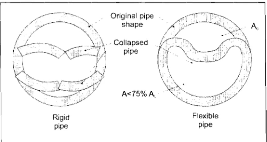
Figure 5.5 Deformation of flexible pipe 26
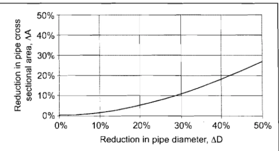
Figure 5.6 Relationship of diameter change to area change 26 Figure 5.7 Collapse modes for rigid and flexible pipes 27 Figure 5.8 Joint displacement 27 Figure 5.9 Longitudinal joint opening 28 Figure 5.10 Angular displacement joint opening 28 Figure 5.11 Root intrusion into a sewer 33 Figure 5.12 Encrustation in a sewer 34 Figure6.l CIPP rehabilitation costs vs sewer diameter 45
Figure 7.1 Elevation view of typical access holes 48
Figure 7.2 Clock reference for access holes 48
Figure 8.1 Pipe and access hole database structure 53
Figure 8.2 Relationships between data tables 54
Figure 8.3 Example data entry form with dropdown lists 55
Figure B.l Probability curves for deterioration 72
FigureB.2 Example distributions ofthe cumulative waiting times 77
I
.
1. General
1.1
Introduction
Sewer collection systems are essential elements of municipal services. To ensure a high level of reliability at the lowest possible cost, asset management systems and procedures that include effective methods for condition assessment and rehabilitation must be imple-mented.This Guideline applies to large sewers (900 mm and larger) and provides owners and operators of sewer systems with suggested methods for managing the assessment and repair of large sewers. The subject areas covered in this Guideline include:
Health and safety issues for inspection and repair
Availability, applicability and limitations of existing technologies for inspection, condition assessment and rehabilitation Failure impact assessment
Collection and management ofreliable data Decision making based on sewer
conditions and failure impact
Projections of future sewer conditions Cost estimates for sewer and access hole inspection and repair.
The steps for the effective management of large sewers and their location in this Guideline are shown in Figure 1.1. In addition, the health and safety issues associated with work in the confined space of a sewer are provided in Section 2. Appendix A provides tables for converting defect codes from other rating systems to the Large Sewer Condition Code
L
Inventory I⦅セイXI
.
Failure impact 。ウウ・ウウG[Gセョエ
I J
Set priority for ...L
I
(Section 3)l
inspection I--- --- ---_.--- ---._-.-..l
Insp.eciion ·1 (Section 4)I ..
_- ._-1.
セセ⦅...
Condition assessmentI
(Section 5 -Sewer pipes [ Se_ction!. -a」セ・ウウ iJoles). d・」ゥウゥッョセMNi making_1_
-1
-I-L
-Future condition RehabilitatiO-;'-\ assessment (Section 6) (Section 4) MMM{]セ.-f
Figure 1.1. Steps for managing sewer assets
Maintenance (not covered by this
Guideline) ⦅セMMセMセj
i
and Rating (LSCCR) system described in this Guideline. Appendix B contains additional information on estimating future conditions of sewers.1.2 Scope
This Guideline applies to large gravity sewers, that is, sewers with a minimum pipe size of900 mm (the minimum accepted size for person entry)22,51. However, many aspects of the Guideline are applicable to sewers of smaller sizes.The Guideline provides a systematic method for the structural defect rating of sewers, brick sewers and access holes and provides informa-tion about current rehabilitainforma-tion methods for large sewers.
The planning and scheduling of sewer rehabili-tation will not depend entirely on the failure impact rating and the condition ratings de-scribed in this document. Other factors such as population growth, plans for installation of other buried services and road surface rehabili-tation will also affect the timing of sewer rehabilitation.
The Guideline also provides a method for rating serviceability defects. The serviceability rating can be used to prioritize maintenance work. However, the decision-making about mainte-nance needs and appropriate techniques are beyond the scope of this Guideline.
1.3 Terminology
The principal terms used in this Guideline and their meanings are as follows:
Access hole: A structure that provides access to the sewer pipe for maintenance, inspection and rehabilitation. Access hole is used inter-changeably with maintenance hole (or manhole - MH for short) and access structure.
Condition: The condition of a sewer pipe or access hole is expressed by six condition ratings as follows: 0 - excellent, I - good, 2 - fair, 3 - poor, 4 - bad, 5 - failure or imminent failure. Condition ratings are also referred to as condition states in theoretical models for predicting future sewer conditions (Appendix B).
When the pipe or access hole is in excellent condition (or as good as new), no defects will be observed during an inspection and its condition is represented by "0".
Defect: A defect is a physical or service deficiency. Defects may originate from the manufacturing or installation process, or may be a result ofnormal wear and tear or third party damage. Defects can be classified as either affecting structural integrity or affecting serviceability.
Durability: Durability32, 12 is the ability of a pipe or access hole to satisfactorily withstand the effects of service conditions to which it is subjected. Or stated more simply, it is the ability of a pipe or access hole to resist wear and deterioration.
Embedment: Embedment is the backfill materials surrounding the pipe extending from the top of the pipe to the base ofthe trench and including bedding.
Failure: Failure of a pipe or access hole occurs when it is no longer able to function as
intended. Failure ofa sewer pipe means that the pipe is no longer able to convey sewage at its design capacity. Modes of failure vary with pipe materials. Condition 5 indicates failure or imminent failure.
Full-line inspection methods: These are inspection methods that are used for continu-ous inspection of a sewer pipe from one access hole to another.
,
..
,
i
In-line test methods: These are test methods used for localized areas, joints or lengths, usually with specialized tools. Inline testing usually involves personentry.
Large sewers: Sewers of900 mm and larger are defined as large sewers. This size is considered the minimum size for which personentry is practical and safe.
Person-entry activities: These are any activi-ties requiring a person to enter the sewer. Pipe bedding: Pipe bedding is structural backfill material placed between the bottom of the pipe and the bottom of the trench.
Service life: Service life is the expected duration that a pipe or access hole will perform satisfactorily based on normal maintenance activities. (For other definitions of service life, refer to References 25,43, and 46.) Remaining service life is the life span of a structural element from the current time to the time of its failure. Design service life is the intended life span from the time of construction to the time offailure, based on the design criteria. Design service life is not a true indicator of the deterioration rate ofthe element materials or when the element will actually fail. Serviceability: Serviceability is the capability of a pipe or access hole to perform the function for which it was designed while exposed to in-situ conditions.
Special-purpose inspection methods: These are inspection methods used for localized areas or lengths (not necessarily for the entire MH to MH length), or to access a particular defect.
i
I
セ
-
,
,
i
2. Health and Safety
Sewers are dangerous work areas because they contain harmful gases, bacteria and other microorganisms, and have insufficient oxygen supply, high humidity, odour and slippery working conditions. Furthermore, flows in many large sewers cannot be diverted so that
inspection or rehabilitation can take place in the absence of flows. Health and safety is paramount and must not be compromised. A safety plan is required for aU personentry activities inside a sewer pipe. Safety procedures must be developed and followed by aU involved personnel. Before any inspection or rehabilitation work commences, safety procedures must be in place and trained personnel responsible for site safety must be identified. Fatalities can occur ifappropriate safety procedures are not foUowed.
Although a national health and safety regula-tion does not exist in Canada, many provinces and municipalities have established their own regulations and procedures for confmed space entry. Any municipality operating a sewer system is urged to establish suitable proce- dures in consultation with provincial authori-ties and other municipalities. For additional information, refer to the fol1owing documents:
Ontario Regulation 213/91: The Occupational Health and Safety Act City of Toronto: Corifined Space Entry and Exit, 1989
Capital Regional District (Victoria, BC): Section 3 Work Procedure (WP) 13: Corifined Space Entry Procedure, CRD ENG Policy/ProceduresManual, 1998 Region of HamiltonWentworth: Confined Space Entry Procedure (developed for a specific project), 1998
Greater Vancouver Regional District: Corifined Space Guidelines, 1999; Confined Space Entry Guidelines for Sewer Entry, 1994; Personal Protective Equipment Policy Statement, 1993 (aU are included in tender documents for sewer work)
City of Regina: Corifined Space Entry Program, City ofRegina, 1997. Minimum requirements for confined space entry are: Proper training of aboveground and belowground personnel participating in the inspection and rehabilitation of sewers Detailed contingency plans for work and rescue Assessment of potential hazards prior to access hole and sewer entry Availability of appropriate protective clothing and equipment (harness, lifelines, breathing apparatus, and hoisting and conveying equipment)
Availability of appropriate tools and equipment that are in good working order Availability of emergency equipment (first-aid kit and fire extinguisher) Notification of appropriate rescue agencies (such as the fue department) prior to commencement ofwork Air quality testing and monitoring prior to and during personentry Maintenance of adequate ventilation and lighting during personentry
i
,
Opening and continuous monitoring of the access holes immediately upstream and downstream from the work area Effective communication between the aboveground and belowground personnelConstant maintenance oflifelines Safe control of surface traffic.
Sewers are hazardous work environments. Any person entering a sewer must be trained in work and safety requirements for confmedspace entry.
I
.
,
i
3. Failure Impact Assessment
The impact of a failure of a large sewer depends on several factors and each sewer is unique. Decisions about sewer rehabilitation are based on two main considerations the impact of failure and the condition of the sewer (Sections 5 and 7).
Failure impact assessment is a way of assess-ing the consequences of failure of the different segments of a sewer system and the likelihood of failure based on the site conditions where the sewer is located. Failure impact assessment is usually done independently of on-site inspection and condition assessment.
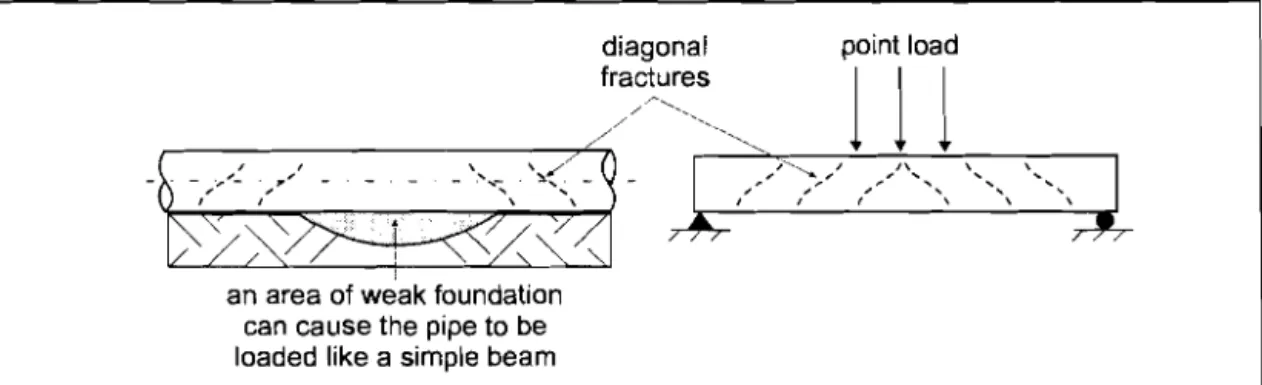
The impact offailure is based on the likelihood of failure and the severity of consequences resulting from failure. For example, the likeli-hood offailure would be high if a fractured sewer were located in unstable soil conditions. The consequences resulting from a failure would be high if a sewer served a large area and no bypass capability existed.
The failure impact assessment rating is used in conjunction with the condition rating to provide a logical and systematic means for determining the priorities for subsequent inspections and the eventual rehabilitation of sewers.
Table 3.1. Major failure impact factors
3.1
Failure Impact Assessment
of Sewer Pipes
Table 3.1 shows the major factors that either affect the likelihood offailure or the severity of consequences resulting from failure. Local impact factors will vary from location to location whereas global impact factors will remain the same for individual MH to MH sewer segments or even for an entire urban area.
3.1.1 Failure impact determination
Numerical values are used to represent the degree of impact should failure occur. Consist-ent assignmConsist-ent of values will provide useful information about the relative degree offailure impact of one sewer or sewer segment to another. When the impact ofa factor is negligi-ble or low, a value of I is assigned, and when the impact is medium or high, values of 1.5 and 3.0 respectively are assigned (Table 3.2, page 8). Each failure impact factor has an established weighting factor that is used in combination with the degree offailure impact in Eq. 3.1 to determine the weighted failure impact factor for a sewer.
Factor Affecting Affecting Local or
the likelihood the severity of global effect
of failure consequences resulting from failure
Sewer location Local
Embedment soil Local
Sewer size Global
Burial depth Global
Sewer function Global
i
I
Failure impact ratings serve two purposes: 1. They establish priorities for sewer inspection (Section 4) and condition assessment (sewer pipes Section 5, access holes Section 7) 2. They serve, in combination with condition rating, as the basis for decisionmaking for the timing for rehabilitation (sewer pipes -Section 6, access holes Section 7) The degree offailure impact of each of the maj or factors is defined in 3.1.2 to 3.1.7. The weighted failure impact factor I is then calculated by: W I" = (0.2)}; + (0.16)I -+-(0.16)1; +(0.16)1, +(0.16)1! + (0.16));, [3.1] Once the weighted failure impact has been calculated, the impact rating R Imp is then determined using Table 3.3. . Table 3.2. Failure impact factors and weights3.1.2 Sewer location The impact of a sewer failure on the public and the environment is affected by its location. Table 3.4 shows the sewer location factor
1;
and the failure impact as a function of land use, traffic, access for repair, location relative to essential facilities and environmental zoning. Figure 3.1 shows an example of assigning sewer location factors. A high sewer location factor has been assigned for the portion of the sewer within the airport perimeter and a low location factor assigned for the portion outside the airport.Failure impact factor Weigbting Symbol Degree of failure impact factor
Low Medium Higb Local
Sewer location (Table 3.4) 0.2 1.0 1.5 3.0 Embedment soil (Table 3.5) 0.16 1.0 1.5 3.0 Global
Sewer size (Table 3.6) 0.16 1, 1.0 1.5 3.0 Burial depth (Table 3.7) 0.16
J.
1.0 1.5 3.0 Sewer function (Table 3.8) 0.16!r
1.0 1.5 3.0 Seismic zone (Table 3.9) 0.161.
1.0 1.5 3.0Table 3.3. Failure impact rating
Weigbted impact Impact rating, factor,Iw R... 1.00 1 1.01 1.60 2 1.61 2.20 3 2.21 2.80 4 > 2.80 5
,
i
Table 3.4. Sewer location factor*
Aspects Degree of failure impact
Low (1;= 1.0) Medium (I; = 1.5) High (I; = 3.0) Land use
Traffic intensity Access for repair
Location (under or adjacent to)
Environmental
Industrial ) or 2 lanes Unrestricted Areas not covered in the next two columns Nonsensitive areas Residential 3 to 5 lanes Limited • high volume tourist areas • high risk installations
or utilities
Environmental conservation zones
Commercial 6 lanes or more Restricted
• high risk installations or utilities
• railroads, rivers, canals or other bodies of water • buildings
• primary access to emergency facilities • airports
Environmental protected zones • Modified from References 10 and II
[ZエセBL Bセ セZLJ ..LLL\セNNNNL^ ... セ v ft le セ <;:; セ セLセ セLG '::-»" v l ' .; セ , Sewage flow direction
-,
...•.. MH105 Airport MH108 Open field-..
" - - Fence Sewer MH107Location factor high =3 Location factor low
1,=1
, '"
;'\
'"'"
,Figure 3.1. Sewer location factor example
i
I
3.1.3 Embedment soil
The characteristics of the embedment soils and the native soils in proximity to a large sewer are an indication of the susceptibility of the sewer to failure. For example, the combination offme embedment soils, high water table and fractures or joint openings in the sewer pipe can result in erosion of the soils supporting the pipe. Silts and fme sands are highly susceptible to erosion) (a phenomenon commonly referred as "piping") even when exposed to small hydro-static heads (less than 1.5 m head) and this loss of support can lead to sewer failure. Table 3.5 shows the embedment soil factor
f,
for various soil types.Table 3.5. Embedment soil factor·
3.1.4 Sewer size
Sewer size affects the selection of rehabilitation methods, the execution of the repairs, and the degree of contamination to the surrounding environment (soil or receiving waters) in the event of a failure. Generally, repair costs increase with increasing sewer size. Table 3.6 shows the sewer size factor
f.
for various sizes of sewer.3.1.5 Burial depth
The degree of difficulty for emergency repairs increases with increasing sewer depth. The difficulty of carrying out an inspection also increases with depth, as do health and safety concerns. Table 3.7 shows the sewer burial depth factor
1;;
for various depths.Embedment soil Degree of failure impact
f.
Medium to high plasticity claysAll clays if sewer was constructed by tunnelling Low 1.0 Low plasticity clays
Fine to medium gravel Well graded sandy gravel Silts, silty fine sands or fine sands
Medium 1.5 Medium to coarse sands High 3.0
*Based on Reference 52
Table 3.6. Sewer size factor·
Sewer diameter/vertical size (h), mm Degree of failure impact
< 900 Low 1.0
900 - 1800 Medium 1.5
> 1800 High 3.0
* Based on Reference 15
Table 3.7. Burial depth factor·
Burial depth (h), m Degree of failure impact
ィセS Low 1.0
S\ィセQo Medium 1.5
h> 10 High 3.0
I
.
i
I
3.1.6 Sewer function
The type of sewage conveyed in a large sewer impacts the degree of both the soil and/or receiving water contamination and the repair difficulty. In general, the failure of sanitary sewers poses a higher degree of impact than the failure of storm sewers44 . Table 3.8 shows the sewer function factor
1;
for different types of sewers. 3.1.7 Seismic zone Earthquakes can cause more damage to defective pipe sections than to nondefective pipe sections. The ground vibrations diminish the soil support for the sewer, particularly for flexible pipe because it has a higher degree of reliance on soil support than rigid pipe. Consideration of the seismic factor is not meant to eliminate damage to sewer systems during earthquakes, but rather to minimize the degree of damage in such events. Table 3.9 shows the seismic zone factorf
for different seismic zones. Z is defmed aセウ
accelerationrelated zone and Zv is defmed as velocityrelated zone42•
Table 3.8. Sewer function factor*
3.2. Failure ImpactAssessment
of Access Holes
Access holes connect two or more sewer pipes together. These pipes can be of different sizes and depths and therefore the impact of their failures may be different. The impact rating of an access hole is defined as being equal to that of the adjoining sewer pipe with the most severe failure impact rating (Figure 3.2, page 12).
3.3 Using Failure Impact
Ratings to Set Priorities
Impact rating maps (Figure 3.3, page 12) can be generated for sewer collection systems using the failure impact rating methodology explained in this Section. Failure impact maps will help not only for identifying priorities for inspection, condition assessment and rehabilitation, but also for planning new sewer extensions. For instance, an impact rating might be used to locate a new sewer away from high failure impact rating areas.
A comprehensive inspection plan is crucial for
Function Degree of failure impact
Col1ector sewer, stonn sewer Low 1.0 Major trunk, sanitary or combined sewer Medium 1.5 Major/regional interceptor, influent and effluent High 3.0 to/from wastewater treatment plant
*Modified from references 10 and \l
Table 3.9. Seismic zone factor"2
Accelerationrelated or
velocityrelated seismic zone, Z., Z, Degree of failure impaet
02 Low 1.0
3 4 Medium 1.5
Access hole impact rating is equal to the highest impact rating of the pipes it connects
(In this case, the outgoing pipe) ___
LMM⦅セ⦅セキ⦅キ⦅。⦅ァ⦅・MMサ
セ
:," Impact rating, R , =2 ( \ r direction
I \ - ·
m\
Access hole
(
セ
y
\ '"---\ \Pipe impact rating, R,mp =1
Pipe impact rating, R,mp = 2
Plan view (NTS.)
Figure 3.2. Access hole failure impact rating
Sewage flow direction
1
4 3 5 Failure impact rating City street,
,
..
i
4. Inspection
the effective management oflarge sewers. to specifications. This inspection should also Inspection is the fIrst step of the condition document any changes to the original design assessment. The condition of a sewer system, that occurred during construction (for exam-in combination with the failure impact assess- ples, alignment changes, location of service ment presented in Section 3, is the basis for connections, or additional access holes). making repair decisions that minimize service
disruptions and minimize costs. It is recommended that the initial inspection be the basis for a full condition assessment Inspections provide information on the (Sections 5 and 7). In addition, because studies physical condition of the sewer and on rates of show many defects result from poor workman-material deterioration. Inspection data help ship and because it may take some time for forecast future conditions of the sewer and these defects to become obvious, it is recom-help determine the need and timing for rehabili- mended that an interim inspection of a new
tation. sewer be made prior to the end of the warranty
period. The inspection should cover the entire Optimal scheduling of inspections will result in length ofthe new or rehabilitated pipeline. savings and minimize the likelihood of sewer This initial inspection will provide valuable failure. This section provides recommendations baseline data that can be used for comparison for inspection frequencies as well as descrip- in future condition assessments.
tions and rough cost estimates for various
inspection techniques. Inspection methods If an existing large sewer has never been described include "fullline" and "special- inspected, an initial inspection should be purpose" methods. Some commonly used "in- performed as early as possible (regardless of line" testing methods are also included. the age of the sewer) to benchmark the sewer
condition. This information can be used to
4.1 Inspection Timing and
determine maintenance and rehabilitationneeds.
Frequency
4.1.1 Initial inspection For sewer systems that have not been part of a comprehensive inspection plan, the following Many sewers have defects of some kind. In points can assist in setting priorities for fIrst some cases, the defects result from normal in-inspection: service deterioration. However, one studyJI determined that the majority of sewer defects 1. Use the failure impact assessment method are a result of poor workmanship. Another described in Section 3 to produce a failure study based on the assessment of 180 km of impact rating map for all large sewers in the sewers44 determined that many defects arise
system. during or shortly after construction. These
fIndings confIrm the need for inspections of 2. Assign high priority to sewers of known
new sewers. (or suspected) problems such as: high
inflow/infIltration (I/I), proximity to a water It is common practice for a municipality (or its main rupture, ground disturbance from delegate) to perform an inspection to confIrm construction activity, or exposure to that a new sewer has been built in conformance abovenormal chemical concentrations.
,
i
3. Consider the schedule for road refurbishment or nearby water main replacement so that if replacement of the sewer pipe by the opencut method is likely, it can be carried out before a new road surface is installed. 4. In high seismic risk zones, assign high priority to sewers installed in soils with high liquefaction characteristics. 4.1.2 Subsequent inspection Optimal scheduling of inspection cycles is an important aspect of good management of large sewers. Many factors must be considered: the cost of inspection, the anticipated condition of the pipe based on the last inspection, the level ofrisk (or likelihood offailure), and the degree of difficulty required to complete an inspection. Fulllength inspection of large sewers should be carried out following the modified WRc (Water Research Centre, United Kingdom) approach shown in Tab Ie 4.1. The recom-mended inspection frequency depends not only on the physical condition state (Sections 5 and 7) but also on the failure impact rating of the sewer (Section 3). The recommended inspection timings in Table 4.1 as well as those used by WRc and the City of Edmonton and others are prescriptive in nature. However, unlike other methods, the determination ofthe timing for the next inspec-tion in Table 4.1 takes the failure impact rating into account. There are several reported attempts to develop inspection decision methods that are more quantitative and thus more specific to individual sewers. Some of these methods are described in Appendix B. It is recommended that inspection frequency guidelines in Table 4.1 be followed until a better quantitative method is developed and validated with field data.
4.2 Full-Line Inspection
Techniques
Fullline inspection means the continuous inspection of a given length of sewer from MH to MH. The inspection techniques covered in this section are summarized in Table 4.2 and a brief description of each of the techniques is provided. Where project information is avail-able, a cost range for the inspection is given. Actual costs of inspection will depend on sewer size and depth, distance between access holes, site and sewer conditions, and availabil-ity of inspectors locally. In general, the quality of the inspection will be enhanced if the sewer has been cleaned prior to inspection.. Table 4.1. Inspection timing based on condition rating and failure impact rating
Condition rating Failure impact rating (Ri•.,,) Time to next inspection (years)
5 I to 5 O'
4 5 0+
I to 4 2 to 6
3 5 3
I to 4 5 to 10
2 5 5
I to 4 10 to 15
I or 0 5 10
I to 4 15 to 25
,
i
Table 4.2. Full-line inspection techniques
Inspection method Application limitations Rangc of costt CCTV
Sonar/CCTV Personentry Stationary camera
Sewers up to 1500 mm diameter, above flowline only, quality decreases as cable length increases
Some flow required, above and below flowline, quality decreases as cable length increases
Sewers 900 mm diameter and larger, visual, above flowline only, health and safety concerns
Applicable only to pipe sections adjacent to access holes, above flowline only, used mainly for preliminary assessment
$2 $14/m $7 $IO/m $2 $20/m
$IOO/MH
t Costs depend on actual joh situations and tend to increase with the increase in pipe burial depth and sewer size. These costs are estimates only.
4.2.1 Closed circuit television (CCTV)
Closed circuit television (CCTV) is an effective tool for the inspection oflarge sewers and it does not require personentry. The inspection procedure involves moving a video camera through the sewer to record the condition of the interior surfaces of the sewer. Modem video technology, including 'panandtilt' and 'fish eye', provides highquality images of the sewer interior. Certified CCTV operators use the video footage to record the type and location of defects. Corresponding condition assessment is carried out subsequently by viewing the inspection tape and the inspection report. CCTV can only capture images ofthe portion of the pipe above the flowline and cannot provide quantitative deformation measurements. However, a skilled operator can detect features such as a hydraulic jump that may indicate a deformed pipe or deformed joint. If it is essen-tial to inspect the pipe below the flowline using CCTV, dewatering ofthe sewer by means of bypass or bypass pumping will be required. Most CCTV tools are suited for pipes up to 1500 rom in diameter52
• The CCTV cameras are
supported by tractors or floats and movement is controlled remotely by an operator on the
surface. For the tractor application, the CCTV camera is placed on a moveable platfonn that allows the camera to be moved closer to a defect. Some cameras have the ability to pan-and-tilt, rotate or zoom to improve inspection quality. Extra lights are often attached to the tractor to improve visibility. The inspection apparatus can be assembled in the sewer or collapsed to fit through a standard access hole and expanded to full size inside the sewer. The tractors can negotiate bends, tum on their own axis and move through areas with debris. Inspections can be perfonned from access hole to access hole. If only one access point is available, inspection is carried out as the CCTV camera travels to the furthest location, and the inspection tractor is reversed to return to the entry point.
Before the tractor- or rig-camera system is used, the expected flowline is estimated. Spacers are placed on the rig to elevate the camera to the appropriate position prior to entry. Ifthe flowline is too high, the camera will be sub-merged, rendering the survey ineffective. In areas where the flow level is high, the camera can be mounted on a float. In such cases, the extent ofthe circumference visible to the camera is diminished and ifthe flow velocity is high, movement of the float and camera may adversely affect the image quality.
,
i
There are some drawbacks to CCTV inspection. than for CCTV inspection alone. As with CCTV Depending on the situation, setup can be a inspection, the setup time for combined sonar-large portion of the overall inspection time. CCTV inspection is usually long in relation to Although power supply cable is available up to the actual inspection time. Inspection costs 1OOOm long, image quality may deteriorate when range from $6/m to $1 O/m for sonar only, and cable longer than 500m is used35
• For long cable $7/m to $1 O/m for combination sonar and
lengths, a booster may be needed to improve CCTV55 •
image transmission. The drag weight of long
cable also becomes a limiting factor. 4.2.3 Person-entry inspection
Visual sewer inspection by trained personnel Although CCTV is an effective means of
can provide qualitative and quantitative inspecting large sewers, it is subject to operator
information about defects. For example, interpretation and an operator may fail to
inspectors can note defects and deterioration, identify defects for various reasons including
detect concrete de-lamination, measure pipe inattention, fatigue or poor image quality. CCTV
deflection, and take close-up photos. Person-operators must have formal training and
entry inspection may be the sole type of certification from a credible organization to
inspection used or may be used to acquire ensure reliability and uniformity of defect
additional information following a CCTV coding. The North America Association of
inspection. In preparation for person-entry Pipeline Inspectors (NAAPI) offers training and
inspection, it is useful to review past reports certification for CCTV operators based on WRc
and to identify locations of particular concern. (Water Research Centre, United Kingdom)
standards.
Person-entry inspectors should receive formal training for visual condition assessment and In general, CCTV inspection cost increases
certification to ensure consistency and with sewer depth because of increased set-up
comparability. In addition, person-entry time and because of the additional cable length
inspectors must have special training for work extending from the surface to the sewer. The
in confmed spaces. As described in Section 2, cost ofCCTV inspection varies from $2/m to
sewers are hazardous work areas and any $14/m55 (not including sewer cleaning costs).
person-entry activity requires strict adherence to safety procedures. The set-up time for
4.2.2 Sonar/CCTV
person-entry inspection is lengthy due to Sonar/CCTV combines the use of sonar to health and safety requirements and the rate of inspect the portion of the sewer below the inspection is affected by safety factors such as flowline and CCTV to inspect above the the duration of bottled air supply.
flowline to give a complete picture of the sewer.
The sonar images can reveal the true shape of As for CCTV inspection, person-entry inspec-the pipe, sedimentation build-up at inspec-the invert tion can only observe defects above the and defects in the pipe wall greater than 4 mm21
• flowline, and there is always the possibility of a
subjective interpretation of defect type and Like CCTV, this inspection technique requires severity. Person-entry inspection may not specially trained personnel both to perform the accurately establish the location of each defect. inspections and to interpret the results. The City of Edmonton costs for person-entry set-up arrangement and length limitations are inspection range from $2/m to $20/m. similar to those for CCTV. However, the
i
I
4.2.4 Stationary camera
Stationary cameras are used to obtain quick and fIrsthand indications of pipe defects in the vicinity of access holes. This technique is often used as a screening tool based on the premise that the sewer line condition is often poorest near the access holes41
• Photos are taken from
the access holes and therefore the distance from the access hole that can be checked depends on the quality of lighting and the zooming capability ofthe camera. The cost is approximately $1 00 per access hole.
4.2.5 New inspection technology Several promising techniques are under development. One of these is Sewer Scanner and Evaluation Technology (SSET), developed in Japan and evaluated by the Civil Engineering Research Foundation (CERF). SSET uses a scanning technique in conjunction with an expert database system to automatically identify defect types on the interior surfaces of sewers2, 23.
4.3 Special-Purpose Inspection
Techniques
Specialpurpose inspection techniques are those used for extraordinary situations (such as surcharged pipe) or are techniques specifIc to certain pipe materials. Table 4.3 summarises the techniques that are described in this section.Table 4.3. Special-purpose inspection techniques
Inspection method Characteristics
4.3.1 Rotary sonic device
Similar to the combined sonarCCTV technique described in 4.2.2, the rotary sonic device can be used to measure deflections in a flexible sewer pipe or a lined pipe or to determine the loss ofmaterial from the interior surface ofa pipe. Sonar operates by measuring the different travel velocities of sound in different materi-als45
. Sonic devices can be used to inspect
portions of the pipe both above and below the flowline, but not simultaneously. The rotary sonic device travels inside the pipe on carriers similar to those used for CCTV cameras and measures the deformation at any given point around the pipe. The cost of using a rotary sonic device ranges from $10 to $13/m 45 (excluding sewer cleaning and mobilization). 4.3.2 Diver inspection CertifIed divers can be used to perform inspections in high flow conditions and in surcharged sections such as inverted siphon sections oflarge sewers. Visibility and extra diffIculty in recording defect severity and location are limiting factors. Diver inspection is a highrisk personentry inspection method with specialized safety requirements. 4.3.3 Systeme mechanique
d'auscultation des conduites (MAC) The MAC system is a test technique used for spot evaluation of the structural strength of pipe and the integrity of the pipesoil struc-ture47
• The sewer must be dewatered before
Rotary sonic device Divers
MAC system
Infrared thermography Ground penetrating radar
Proven technique, useful for deflection measurement of flexible pipe, used for sewers up to 1500 mrn in diameter
High risk technique for surcharged sewers, limited effectiveness in high turbidity Proven technique, dewatering or low flows required
Developing technique, limited effectiveness in areas congested with buried utilities Developing technique, soilcondition dependent
i
I
testing. Because it is not always possible to There are four ways of performing infrared dewater large sewers, this technique is more thermographic inspections.
easily used to do spot checks of new sewers
prior to use. A computer and loading apparatus The operator wears the equipment and are then placed inside the sewer. The load is walks along the inspection area. applied and a sonar head measures the pipe
deformation. The computer uses the fmite The equipment is installed on a platform element method to determine the longitudinal and records the thermal images from an rigidity, elongation and safety factor. The elevated position.
method is expensive ($50/m) and requires
specialized equipment and personnel. The equipment is mounted on a vehicle.
4.3.4 Inspection beyond the pipe wall The equipment is mounted on a helicopter
(void detection) to inspect a large area.
The integrity of the supporting soil structure is Infrared thermography appears to be economi-very important50 to sewer performance, and loss
cal (the average cost is $5/m) and safe. Data of soil support may lead to collapse of the can be combined with other inspection results sewer. Factors that affect the rate of soil loss to provide greater accuracy and the results can include size ofa fracture or open joint in the help differentiate the sections in need ofrepair sewer pipe, groundwater table level, character- from those in good conditionl7.
istics of embedment soils, occurrence of
adjacent water main bursts, and adjacent Testing can be done during the day or night construction activities that disturb pipe and there is little inconvenience to the public. embedment. The movement of soils through However, analysis can be difficult in areas fractures and joint openings will result in voids congested by other services. The ground and loss of support for the pipe. Methods of surface must be dry, with no water or snow void detection are relatively new and still under present. Inspection can usually be performed development. Therefore it is essential to after at least one day without rain.
validate the fmdings of void detection tests.
Surface inspection is the careful investigation Infrared thermography uses latent heat from of the area above the sewer to check for dips or fluid or gases to detect leakage and voids. It is settlement that might indicate the presence of a noncontact, nondestructive method used to voids around the sewer pipe, or pipe deforma-inspect large areas from above ground. It can tion. The presence of surface irregularities will detect voids but cannot ascertain whether the indicate a high priority need for a detailed void is due to soil loss or is a void in a struc- inspection ofthe pipe interior. ture (such as a water valve box). In addition, it does not indicate the size of the void. The Ground penetrating radar (GPR) can be used components of the inspection include an both from inside the pipe and from the surface infrared scanner head and detector, real time
to identify and locate voids in the soil sur-microprocessor, data acquisition or analysis
rounding a pipe. GPR emits electromagnetic equipment, and image recording and retrieving energy pulses into the ground, and the
devices. reflection and refraction by subsurface layers
or buried objects are measured. The depth of investigation can be up to 100 m, depending on soil types. GPR has little effectiveness for clay soils or soils with high electrical conductivityl7.
セ
i
I
GPR has been used successfully in combina- Coring through the pipe wall can be used to tion with sonar and CCTV30 to detect cavities determine the condition ofthe pipe's exterior
around sewer pipes. In one case, a remotely surface and to detect suspected voids behind controlled vehicle equipped with sonar, high- the pipe wall. Additional laboratory tests can be resolution video and GPR was placed in the performed on the core samples.
sewer. The GPR transducer was placed against
the inside wall of the sewer and the return Insitu strength testing uses portable test tools signal was recorded as well as the position of (for example, Schmidt Hammer) to test the the defect. The results of the GPR survey were strength of the pipe material.
correlated with video and sonar data. Known
voids were detected (grave vaults in this case) Other methods include: and other detected voids were confirmed by
boring.
Joint testing to determine joint water-tightness
4.4 In-Line Testing Methods
Sampling interior pipe wall deposits for Inline test methods are methods used for laboratory determination of chemical specific testing of known or suspected trouble composition
areas.
4.4.2 Other inspection methods 4.4.1 Person-entry test methods
Flow measurements can be used to fmd The following tests require personentry and obstructions and flow irregularities. Automatic therefore they need to be done when sewer flow meters (for examples, mUltirange ultra-
flows are low. sonic sensor and pressure transducer with
velocity doppler sensors) can measure and .Impact echo is a nondestructive test for record flow depth and velocity, and can be
determining the thickness of the wall of sewer used to record surcharge events. pipe. It can also detect voids in the supporting
soil to some extent. One method uses a hammer Locations of inflow and infiltration and root to excite the pipe wall and a load cell to measure intrusions can be identified using a customized the force. Geophones or accelerometers two infrared system16
• The probe is encapsulated to
types of receiver transducers are used to protect it from the sewer conditions and is measure response to the impact. The dynamic placed on a skid similar to the type used for stiffness of the pipe material is determined to video (CCTV) inspection. This method can indicate whether voids or defects are present in differentiate between sewer effluent and the pipe walp4. incoming water (infiltration) based on their temperatures. The rate of inspection is up to A second method uses a handheld radar 400rnlday. antenna that is passed over the sewer wall. This method is able to differentiate segments with intact sewersoil structures from ones with cracks, voids or other defects34.
,
..
i
i
I
5.
Condition Assessment for Pipe
5.1 LSCCR - Large Sewer
Condition Coding and
Rating
Careful assessment of the physical condition of sewers is fundamental to sound management of a sewer system. The condition rating, in combination with the failure impact rating described in Section 3, is the basis for making rational decisions for the timing of inspection, mainte-nance and repair work.
The Large Sewer Condition Coding and Rating (LSCCR) method de-scribed in this Section is based on information adopted and modified from sewer condition assessment procedures used by the City of Edmonton15
, the City ofPhoenixlo
and the Water Research Centre52 ,
(United Kingdom). It is thorough yet easy to use. Appendix A provides tables for converting condition codes from these other systems to the LSCCR system.
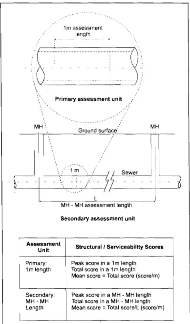
The Large Sewer Condition Coding and Rating (LSCCR) system uses a one-metre pipe segment as the primary unit of assessment and the MH to MH length as the secondary unit (Figure 5.1). This means the inspection data can be used to identify worst-case localized prob-lems or to identify lengths of sewer that are in poor condition overall. Where a MH to MH length is more than 120 m, it should be divided into equal sub-lengths smaller than 120 m. Certain defects represent structural deficiencies in the sewer system-others represent serviceability (or
operational) deficiencies. It is logical to separate these two general types of defects since structural deficiencies usually entail repair (rehabilitation) actions while serviceabil-ity deficiencies usually entail maintenance activities. Two physical condition ratings are used:
._----1m assessment length
\b••{••·•·•••••••·•··••
·.i••••••
セᄋN
\\
.
Primary assessment unit'. MH\ MH Ground ウオイヲ。」セ I II ....· I . . . . MQMセMMB "
Aセ
\
-E-
セ
-
BGNZNセ
j' - /,' -
jf-
Sewer:3
7 iセMMMMMiヲMMMセ L MH - MH assessment length Secondary assessment unitAssessment
Unit Structural I Serviceability Scores
Primary: Peak score in a 1m length
1m length Total score in a 1m length
Mean score = Total score (score/m)
Secondary: Peak score in a MH - MH length
MH-MH Total score in a MH - MH length
Length Mean score
=
Total score/L (score/m)
i
I
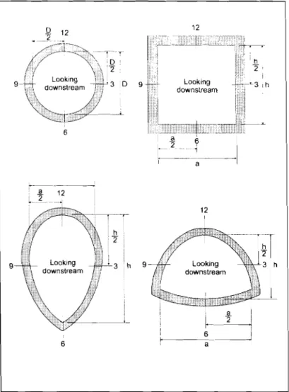
9 Structural condition rating for structural deficiencies Serviceability condition rating for serviceability deficiencies.The clock reference system is used to provide standardized defect positioning. Looking downstream, the 12 o'clock position is the top of the sewer pipe and 6 o'clock is the pipe invert (Figure 5.2). For pipe shapes not covered by Figure 5.2, the user will need to defme the clock positions that best suit a given shape. Chainage is used to defme the location and extent of defects in the longitudinal direction. 12 セ 12 6 a 12 2 12
3
I セイ 2 1 h31
1 h \ I 6 6 a セFigure 5.2 Clock reference for sewer inspection and condition assessment
5.2 Structural Defect Coding for
Pipe
Table 5.1 shows the types of defects that can be encountered for various pipe materials (Section 5.4 deals specifically with brick sewers). Each defect is recorded using a two or three-letter defect coding system as follows: First letter: defect type (for example, fracture or crack) Second letter (ifneeded): identifies the direction ofthe defect as circumferential (direction along the circumference ofthe pipe's cross section), longitudinal (direction parallel to the pipe axis, or diagonal (defects between 30° and 60° with respect to the longitudinal direction). Third letter: Identifies the severity of the defect. Severity is coded as light (L), moderate (M) or severe (S). defect type (F, C, D, etc.)
+
o
o
7
severity (L, M, S)DOD
t direction (C, L, D) For example, the structural defect coding FLL represents a fracture defect in the longitudinal direction and its severity is light. 5.2.1 Fracture (F)A fracture is a "through" crack and/or open crack that is more than 5 rom wide (Figure 5.3). Fractures are sometimes accompanied by deformation and evidence of infiltration (traces of soil). It is a challenge to differentiate cracks from fractures when fractures are closed on the