HAL Id: hal-02908162
https://hal.archives-ouvertes.fr/hal-02908162
Submitted on 28 Jul 2020HAL is a multi-disciplinary open access archive for the deposit and dissemination of sci-entific research documents, whether they are pub-lished or not. The documents may come from teaching and research institutions in France or abroad, or from public or private research centers.
L’archive ouverte pluridisciplinaire HAL, est destinée au dépôt et à la diffusion de documents scientifiques de niveau recherche, publiés ou non, émanant des établissements d’enseignement et de recherche français ou étrangers, des laboratoires publics ou privés.
synthesis and modification for electrophoretic inks
formulation
Béatrice Serment, Manuel Gaudon, Alain Demourgues, Amélie Noël,
Guillaume Fleury, Eric Cloutet, Georges Hadziioannou, Cyril Brochon
To cite this version:
Béatrice Serment, Manuel Gaudon, Alain Demourgues, Amélie Noël, Guillaume Fleury, et al.. Cyan Ni1-xAl2+2x/3�x/3O4 single phase pigments synthesis and modification for electrophoretic inks for-mulation. ACS Omega, ACS Publications, 2020, �10.1021/acsomega.0c01289�. �hal-02908162�
Cyan Ni1-xAl2+2x/3
x/3O4 single phase pigments
synthesis and modification for electrophoretic inks
formulation.
Béatrice Serment†‡, Manuel Gaudon, †*, Alain Demourgues†, Amélie Noël‡, Guillaume Fleury‡,
Eric Cloutet‡, Georges Hadziioannou‡ and Cyril Brochon, ‡*
†CNRS, Univ. Bordeaux, Bordeaux INP, ICMCB, UMR 5026, F-33600 Pessac, France
‡ CNRS, Univ. Bordeaux, Bordeaux INP, LCPO, UMR 5629, F-33615, Pessac, France
KEYWORDS
Electrophoretic inks, cyan pigment, spinel, hybrids particles, Pechini, dispersion polymerization
ABSTRACT
Cyan Ni1-xAl2+2x/3O4 single phase pigments with various Ni:Al atomic ratios (from 1:2 down to
1:4) have been prepared by sol gel route (Pechini) followed by post-annealing treatments. Nickel aluminates crystallize in the well-known spinel structure (Fd-3m space group) where metals are located at two different Wyckoff positions: 16d (octahedron) and 8a (tetrahedron). Based on XRD
Rietveld refinements, Ni2+ cations are shown to be partially located in both tetrahedral and
octahedral sites and, in addition, cationic vacancies occupy Oh environment. In the pure phase series, Ni/Al = 0.35, 0.40, 0.45, as the Al content increases, the Ni2+ rate in Td site decreases for
Ni/Al=0.45, thus altering the cyan color ; within this series, the most saturated cyan coloration is reached for the highest Al concentration. Inorganic pigment drawbacks are their high density and hydrophilic surface, which induced sedimentation and aggregation in non-polar media used in electrophoretic inks. Hybrid core shell particles pigments have been synthesized from cyan pigments by using nitroxide mediated radical polymerization (NMRP) with methyl methacrylate monomer in isopar G leading to a dispersion of electrically charged hybrids in apolar media. Surface functionalization of the pigments by OTS and DTS modifiers have been compared. The
inorganic pigments are successfully encapsulated by organic shells to allow a strong decrease of their density. Cyan inks, adequate for their use in e-book readers or other electrophoretic displays, taking further advantage of the high contrast ratio and reflectivity of inorganic pigments as regards to organic dyes, have been stabilized.
1. INTRODUCTION
Electrophoretic image displays (EPID) raise a strong interest since the first studies of Jacobson et
al.1, 2 describing the high potential of these new displays: low cost, ultralow power consumption,
good flexibility and reliability. The commercialized black/white electronic books such as Kindle by Amazon® are still the most developed applications for EPID in the market despite of potential
broader applications.3 Actually, most of e-books readers are in grey scale even if 3-colours systems
thanks to the use of colour-filters have been recently emerging 4, 5.This type of colour system is
not as effective as the use of pigments. Moreover, few studies reported the synthesis of coloured electrophoretic inks with the encapsulation of dyes to obtain chromatic EPID 4, 6–8.The required
properties to obtain performant EPID are mainly high surface charges, a good dispersion stability of the pigment particles and low inter-particles interactions to ensure the long-term electrophoretic
control of the ink coloration 9. Electrophoretic inks are typically prepared in a low-cost
electrophoretic medium such as Isopar G. The use of inorganic pigments allows a high contrast ratio and reflectivity of the ink with no loss of coloration with time compared with encapsulated dyes. Actually, Wen et al. have demonstrated that polymer particles filled with a dye have a reflectance spectrum that decrease over 30% after 56h 10. Due to this bottleneck, it is preferable to
use inorganic pigment to reach good contrast and long-term stability. Nevertheless, inorganic pigments suffer from their high density and hydrophilic surface, which induce sedimentation and aggregation in non-polar media. To tackle these challenges, the inorganic pigments must be encapsulated in an organic shell allowing a decrease of both the strength of the interactions between the particles and the overall density 11.
Cyan pigments are obviously of a great interest, because cyan is one of the three subtractive colours. Cyan pigments from copper and nickel phtalocyanines have been used as hybrid particles for photoelectrophoretic imaging processes 12. Copper is an adequate chromophore cation for cyan
pigment application: copper being associated with cyan coloration into inorganic oxides since, for instance, copper is the chromophore cation in the turquoise natural stone (Cu-doped CaAl6(PO4)4(OH)8,4H2O chemical composition). Beautiful cyan hues were recently synthesized
pigments with too high luminosity) 13. In our own research group, cyan pigments have been already
developed using nickel chromophore in spinel structure implying a distribution of nickel ion in octahedral and tetrahedral sites: Zn1-xNixAl2O4 solid solutions showed a colour shift from green to
blue, due to the modulation of the cationic distribution in the aluminate spinel lattice 14.
Spinel-type oxide represents one of the most studied class of materials in the solid-state science because of their relevant magnetic, refractory, semi-conducting and colouring properties. The incorporation of transition metal ions into stable diamagnetic spinels is a successful methodology to obtain materials with a very intense colour. This structure features the general AB2O4 formula in which
A and B are cations occupying tetrahedral and octahedral sites. Assuming A2+ and B3+ cations,
there are two ideal crystallographic structures: the first one is the direct spinel, in which the tetrahedral sites are occupied by A2+ cation and the octahedral sites by the B3+ cation; the second
one is the inverse spinel, in which all tetrahedral sites are occupied by B3+ cation, while A2+ and
B3+ cations share in equivalent proportion the octahedral sites 15, 16. In the NiAl
2O4 structure, the
cation arrangement is typical of a partially inverse spinel (Ni1-zAlz)[NizAl2-z]O4, in which Ni2+ and
Al3+ are randomly located in both tetrahedral and octahedral positions respectively. NiAl
2O4
pigments have been prepared by various routes such as sol-gel 17, 18, solid state reaction 19,
microwave 20, 21, sonochemical 22, Pechini method 23, thermal decomposition of polynuclear malate
complex 24, mechano-chemical synthesis 25, and combustion route 26, 27.
However, it is still difficult to prepare the stoichiometric NiAl2O4 because of the persistent NiO
impurity even if the Ni:Al 1:2 molar ratio is well controlled. For instance, Cooley and Reed 28 have
shown the occurrence of NiO impurity in the final compound despite heat treatments performed at 1664 K for 2 days. In the same way, Han et al. have studied the effect of the sintering temperature and time for this bi-phasic system and showed that there is no mean to reduce the NiO impurity quantity starting from a Ni:Al 1:2 stoichiometric mixture even after very long treatment at high temperatures 29. This residue of NiO besides the NiAl2O4 main compound, which is of dark green
coloured, drastically limits the application of nickel aluminate spinel as cyan pigment. To overtake
this problem, Subramanian et al. 30 prepared over-stoichiometric aluminum compounds leading to
a pure-phase sample with a Ni0.91Al2.06O4 composition.
This paper firstly deals with the elaboration of Ni1-xAl2+2x/3O4 (the Ni/Al atomic ratio varying from
1:2 to 1:4) using the sol-gel synthesis known as Pechini route. The as-prepared gels were subsequently submitted to post-annealing treatments under air. The resulting powders were characterized by XRD Rietveld refinements combined with diffuse reflectance and TEM analysis. In a second part, these powders have been firstly modified by silanes chains and these hybrid
particles were then formulated by a nitroxide mediated radical polymerization of MMA (NMRP) in Isopar G. The inks have been characterized by turbidity measurements to evaluate their stability over time. Charge, electrophoretic mobility, density and particles diameter have been also measured and these parameters were correlated with the ink stability.
2. RESULTS AND DISCUSSION
Synthesis and characterization of the NiAl2+xO4+ compounds
The Ni1-xAl2+2x/3O4 pigments with different Ni/Al molar ratios (from 0.25 up to 0.5 (Ni/Al =
1-x/(2+2x/3) = 0.25; 0.30; 0.35; 0.40; 0.45 and 0.5; i.e. 6 Ni1-xAl2+2x/3O4 samples from x 0.4 down
to x = 0) were prepared using the Pechini sol-gel route followed by a post-annealing under air atmosphere at 1400°C to ensure the cationic homogenization.
The X-ray diffraction patterns of the as-prepared powders are reported in Figure 1. On the basis of XRD data, a single spinel phase is obtained for Ni/Al molar ratios between 0.35 and 0.45. For the extreme Ni/Al ratios (0.25, 0.30 and 0.5), biphasic systems are observed. Indeed, a NiO phase
(with R-3m space group and where Ni2+ are located in octahedral sites) is detected for the 0.50
Ni/Al ratio while a α-Al2O3 alumina phase (with R-3c space group and where Al3+are located in
octahedral sites) is retrieved for the 0.30 and the 0.25 Ni/Al ratios. To estimate the proportion of each phase, to refine unit-cell parameters of the main spinel phase and also, to get an idea of the Ni2+-Al3+ cationic distribution inside the spinel framework, Rietveld refinements of XRD patterns
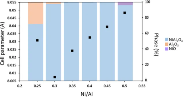
were performed. First, as shown in the Figure 2, a decrease of the spinel unit-cell parameter, from 8.048 Å up to 8.005 Å, is noticed with the increase of Al content for monophasic powder. This tendency is particularly apparent for samples with Ni/Al atomic ratio varying between 0.35 and 0.45. Such an evolution is related to the evolution of the ionic radii for Ni2+ and Al3+ depending
on their localization (0.55 Å and 0.39 Å in tetrahedral site for Ni2+ and Al3+ ,respectively and 0.69
Å and 0.535 Å in octahedral site for Ni2+ and Al3+,respectively). However, as Al content increases,
the stabilization of cationic vacancies should contribute to a decrease of the reticular energy and the coulombic interactions, and could thus be associated to an increase of the cell parameter. To
strengthen the discussion, one can argue that the α-Al2O3 oxide with spinel structure (and a
chemical formulae which can be written as Al8/3 1/3O4), exhibits a cell parameter close to that of
NiAl2O4 spinel (7.90 Å < a < 7.95 Å, 31, 32), despite the occurrence of only Al3+, but thanks to its
high vacancy rate. Thus, the decrease of unit-cell parameter with Al content is not as large as expected because of the compensation from the cationic vacancies.
Each phase proportion has been obtained from Rietveld refinement of all the phases indexed on the XRD diagrams and is also reported in the Figure 2. For a Ni/Al=0.50 ratio, there is 96 % of spinel phase and 4% of NiO. For Ni/Al ratios equal to 0.25 and 0.30, there is respectively 72% and 98% of NiAl2O4 and 28% and 2% of Al2O3 phases. Further investigation was performed on the
Ni/Al = 0.4 pure sample in order to extract the cationic distribution (between Al3+, Ni2+ and
vacancies) in the tetrahedral site-octahedral site cationic sub-network. The Ni/Al = 0.4 sample gets
a chemical composition which can be written as Ni0.84Al2.11 0.05O4. Unfortunately, the
occupancies of the tetrahedral and octahedral sites are impacted by the Ni-Al inversion rate as well, in the same time, as the positioning of the vacancies. Hence, a choice has to be made in the refinement process and we proposed to perform and compare three refinements procedure: (i) a
first refinement considering NiAl2O4 stoichiometric composition, for which the occupancies
between tetrahedral and octahedral site is impacted only by the Ni-Al inversion rate: i.e., only the z inversion parameter assuming the (Ni1-zAlz)[NizAl2-z]O4 crystal framework is refined; (ii) a
second refinement considering all cationic vacancies are located into octahedral sites, i.e., assuming (Ni0.84-zAl0.16+z) [Al1.95-zNiz 0.05]O4 composition; (iii) a third refinement considering all
cationic vacancies are located into tetrahedral sites, i.e., assuming (Ni0.84-zAl0.11+z 0.05) [Al 2.00-zNiz]O4 composition.
In the Figure SI-1, considering the experimental XRD diffractogram of the Ni/Al = 0.4 sample, the three difference signals between calculated and experimental data obtained from the three refinement procedures, are superimposed. No significant difference between the qualities of the refinements (taking into account the RB reliability factor on Table 1) is observed comparing the
different applied processes, even if the location of the vacancies into octahedral sites (i.e. model II) tends to show that this is the best option. This is confirmed by the correlation factors issued from the three refinement procedures, which are reported in the Table 1. Hence, it is very difficult to conclude on the exact cation distribution inside the spinel network. Interestingly, one can note that the calculated quantity of nickel and aluminum located in octahedral or tetrahedral sites are strongly influenced by the refinement process. As illustration, the ratios between the nickel in tetrahedral site and the nickel in octahedral site equals 0.18/0.82=0.22, 0.39/0.45=0.87 and 0.55/0.29=1.89 for the first, second and third refinement processes, respectively. Thus, the chromophore ion (nickel ion) distribution into the tetrahedral and octahedral sites, which governs the colorimetric properties of the spinel compounds, is difficult to precisely assert. This last point will be discussed in the following section as regards to UV-Visible and optical absorption properties around Ni2+ chromophores stabilized in Oh and Td sites.
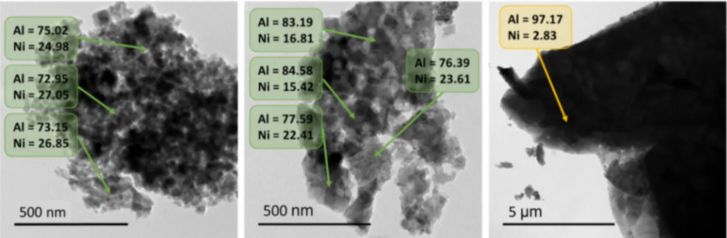
TEM investigations combined with EDS analyses of Ni1-xAl2+2x/3O4 pigments with a (Ni/Al) ratios
equal to 0.25 and 0.40 were performed. The aim is to analyze and compare the morphology of the biphasic or monophasic samples (particle sizes of the spinel, NiO and Al2O3 phases) and to check
the cation distribution (Ni2+ and Al3+ cation distribution). Figure 3 shows the TEM images
collected on the three analyzed samples and the atomic percentage of each cation in various areas is indicated on TEM images. The first micrograph (Figure 3, left side) corresponding to the Ni/Al = 0.4 sample, confirms the occurrence of a monophasic sample, since it exhibits some crystallites with isotropic morphology (with roughly 20-30 nm diameter) partially aggregated. The unique Ni/Al local ratio, i.e. a homogeneous cationic distribution observed in the whole sample, is calculated to 0.41 (average value), a value in perfect agreement with the target composition. However, one can observe a multimodal and large particle size distribution for the two biphasic samples with a Ni/Al ratio equal to 0.40 or 0.25 respectively. For illustration, for the sample Ni/Al = 0.25, a bimodal particle size distribution is clearly evidenced with a first sub-population of particles with a diameter about 10 nm and a second sub-population with particles size about 30 nm (central image, Figure 3). Significant deviations of the Ni/Al ratio are shown depending on the analyzed area. Furthermore, large and isolated aggregates constituted of faceted crystals are also observed on this sample (right panel, Figure 3). The STEM analyses show that the big aggregates are very rich in aluminum cation and should correspond to the corindon-type phase detected in the X-ray diffraction patterns. This Ni/Al = 0.25 sample, in agreement with the XRD analyses, exhibits the occurrence of two phase-types: one spinel-type phase with a non-homogeneous Ni/Al ratio and one corundum-type (α-Al2O3) phase.
UV-Vis-NIR absorbance curves (Kubelka Munk transforms) are superimposed for the various as-prepared samples in Figure 4. In perfect agreement with X-ray diffraction pattern refinement showing that the Ni1-xAl2+2x/3O4 compounds are partially inverse, the d-d transitions associated to
the nickel chromophore in tetrahedral (red transitions) and octahedral (blue transitions) coordination are apparent on the optical spectra in all cases. Five bands are observed, two of them are centered at 400 nm and 700 nm and can be attributed to the nickel (II) ion in octahedral coordination with 3A2g(F)→ 3T1g (P) and 3A2g(F)→ 3T1g (F) transitions, respectively. A first high
energy triplet indexed as a 3T1 (F) → 3T1 (P) transition (due to the L-S Russel-Saunders coupling)
is observed in the visible range at 650 nm, while a second low energy triplet in the NIR range (between 1500 and 3000 nm) can be indexed as a 3T1 (F)→ 3T2 (F) transition. Both triplets can be
associated with nickel(II) ion in a tetrahedral coordination. The last large multiplet centered at 1150 nm is more difficult to index because it could correspond to the superimposition of transitions
taking their origin for nickel (II) ion in both [4] and [6] coordination numbers: the 3T1(F)→ 3A2
(F) transition for the four-fold coordinated site and the 3A2g(F)→ 3T2g (F) transition considering an
octahedral environment. The Racah parameter and crystal field splitting of Ni2+ (3d8) in each site
have been calculated based on Tanabe-Sugano diagrams (d2 for Ni2+[Td] and d8 for Ni2+ [Oh]) 33– 36. The results are BNi2+(Td) = 812 cm-1 (10Dq = 0.57 eV) and BNi2+(Oh) = 860 cm-1 (10 Dq = 1.06
eV). Moreover, nephelauxetic effect can be calculated with Bfree = 1041 cm-1 and β(Ni2+ (Td)) =
0.78 and β(Ni2+ (Oh)) = 0.83, in good agreement with the stronger covalent character of Ni-O bond
in Td site. Indeed, the absorption bands for the Ni2+ in tetrahedral sites are centered at 2551 nm
and at 1150 nm in the near infrared region. About the Ni2+ in octahedral site, the second transition
corresponds to the absorption band centered at 1162 nm. Furthermore, for all samples, a charge transfer band (CTB) is located at about 350 nm and associated to O2- Ni2+ electronic transfer, as
expected for this kind of wide-gap semi conducting oxide. Besides an absorption band is observed
at 776 nm and can be attributed to the 3T
1 (F) → 1E(D) forbidden transition of the Ni2+ in
tetrahedral site. Moreover, one can see that the band intensity centered at 650 nm evolves significantly versus the Ni/Al molar ratio. Indeed, there is an increase of the K/S absorption when the Ni/Al ratio decreases from 0.5 to 0.4 and a drop of intensity after 0.4.
Two effects affect the compounds coloration: the purity of the as-prepared spinel phase and the intensity of the visible absorption bands, especially the evolution of the more intense visible band
(the triplet located at about 650 nm related to Ni2+ in tetrahedral site). L*, a* and b* colour
parameters were extracted from diffuse reflectance curves, what allows the L*a*b* RGB colour space transformation, the representation of the colour of each compound has been done with any common software (Figure 4, inset). All the samples exhibit a cyan coloration with strongly negative a* hue parameter (green-red axis), i.e. an important green component, and strongly negative b* parameter (blue-yellow axis), i.e. an important blue component. For supporting the discussion, one can remind that the most saturated cyan which can be imagined, corresponding to RGB trichromatic parameters with a null red component and the maximal value for both green and blue components, is associated to L*= 62.6; a*= -33.7; b*= -41.6. The as-prepared compounds exhibit beautiful and intense cyan coloration with L*=51.81; a*=-23.11; b*=-30.80 for the Ni/Al=0.4 composition. When the system is biphasic with NiO impurity, the colour is more greenish (for Ni/Al = 0.5 molar ratio the b* parameter is less negative) and this can be reasonably
attributed to the green colour of the NiO particles. When the system is biphasic with α-Al2O3
impurity, an increase of the L* luminosity parameter is observed from 51-54 for the pure spinel
attributed to the white colour of Al2O3 pure phase. It is noteworthy that the increase of the green
component of the color for the Ni/Al = 0.25 sample with large part of alumina impurity, is probably
associated to the insertion of Ni2+ ion into these α-alumina phase (exhibiting octahedral
coordination sites, only). The three pure spinel samples (Ni/Al =0.35, 0.40 and 0.45) exhibit very similar L*, a* and b* parameter. However, a careful comparison of evolution of band intensities in this series, associated to Td site (triplet around 650 nm corresponding to 3T1 (F) → 3T1 (P)
transition) and around 700 nm related to octahedral coordination (3A2g(F)→ 3T1g (F) transition)
seems to show that the Ni2+ occupancy in Td site is maximum for Ni/Al atomic ratio equal to 0.4
and 0.35. The acentric character of Td site leads to high intensity of associated bands compared to those related to Oh site where the local environment is centrosymmetric. Indeed, for Ni/Al =0.45 composition, the triplet intensity around 650 nm associated to Td site decreases more compared to that of other atomic ratio, whereas the band intensity related to Oh environment remains maximum and comparable to the Ni/Al=0.40 composition. It means in first approximation that the Ni2+ rate
in Oh coordination raises as the Al content decreases and the composition with the best cyan hue can be optimized as the Ni2+ rate in Td site is maximum. Thereafter, the Ni/Al molar ratio equal to
0.40: Ni0.84Al2.11 0.05O4 compound (in the middle of the range of compositions leading to pure
spinel phase) will be used for the electrophoretic ink preparation. Ni0.84Al2.11 0.05O4 pigment characteristics
Prior to the synthesis of hybrid particles, measurement of the isoelectric point of the pigment needs to be carried out in order to get specific information about its charge. The pigments were dispersed in aqueous media at different pH between 2 to 12 and the electrophoretic mobility was measured for each sample. The isoelectric point (i.e. the point of zero charge) for this particular pigment was determined at 3.5 as shown in Figure SI-2. In a second step, the density and reflective point of the pigment were also calculated since it is important to have a pigment with a density close to that of the dispersant medium (Isopar-G with ρ = 0.748) as well as a high refractive index to improve the contrast ratio. The density 𝜌 calculated using Equation 1 is 4.2975 for a spinel structure Ni0.84Al2.11O4. For a unit cell of Z monomeric units, the density 𝜌 of the crystalline region is given
by the equation 1, where Na is Avogadro’s number (6.022 x 10²³), V is the volume of the unit cell
and Mw is the molecular weight of the monomeric unit.
𝜌 𝑍. 𝑀𝑤
𝑁𝑎. 𝑉
Equation 1
The Glastone-Dale formula (Equation 2) has been used to estimate the refractive index of this powder. For that, ρ is the density of the complex oxide and the terms ρi and ki are the mass fraction
and the molar refractivity in cm3/g of each oxide, respectively (kNiO = 0.2011 and kAl2O3 = 0.19125 37) . The refractive index is about 1.8316.
𝑛 1 𝜌 𝑁𝑖 . 𝐴𝑙 . 𝑂 𝜌 . 𝑘 Equation 2
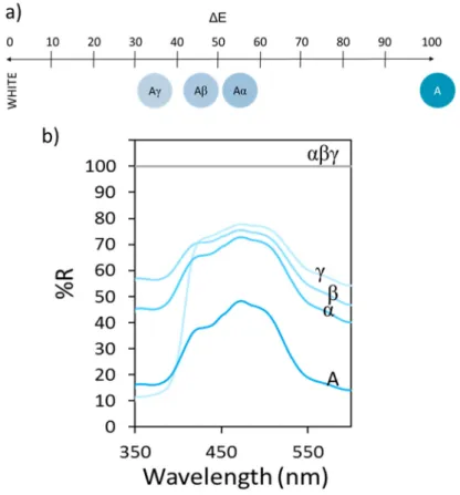
Finally, the tinting strength has been measured in order to evaluate the contrast when this pigment
is mixed with white one. Mixtures of the pigment with three different white powders (TiO2 named
γ, Al2O3 named β and CaCO3 named α) which have different refractive index (n(TiO2) = 2.61,
n(Al2O3) = 1.77) and n(CaCO3) = 1.63) were prepared. Figure 5 shows the diffuse reflectance
spectra of Ni0.84Al2.11 0.05O4 pigment mixed with 50 wt.% of those white powders and then the
evolution of the optical contrast for which white pigments have been taken as reference. Reflectance curves show an intermediate behaviour for mixtures in comparison with Ni0.84Al2.11 0.05O4 and white pigments curves. The more the white pigment refractive index, the
less the optical contrast. An optical contrast about 50-60% is obtained using calcium carbonate meanwhile with titanium oxide it is about 30-40%. Hence, the tinting strength of our cyan pigment is more or less equivalent as that of calcium carbonate.
Surface modification of the Ni0.84Al2.11 0.05O4 compound
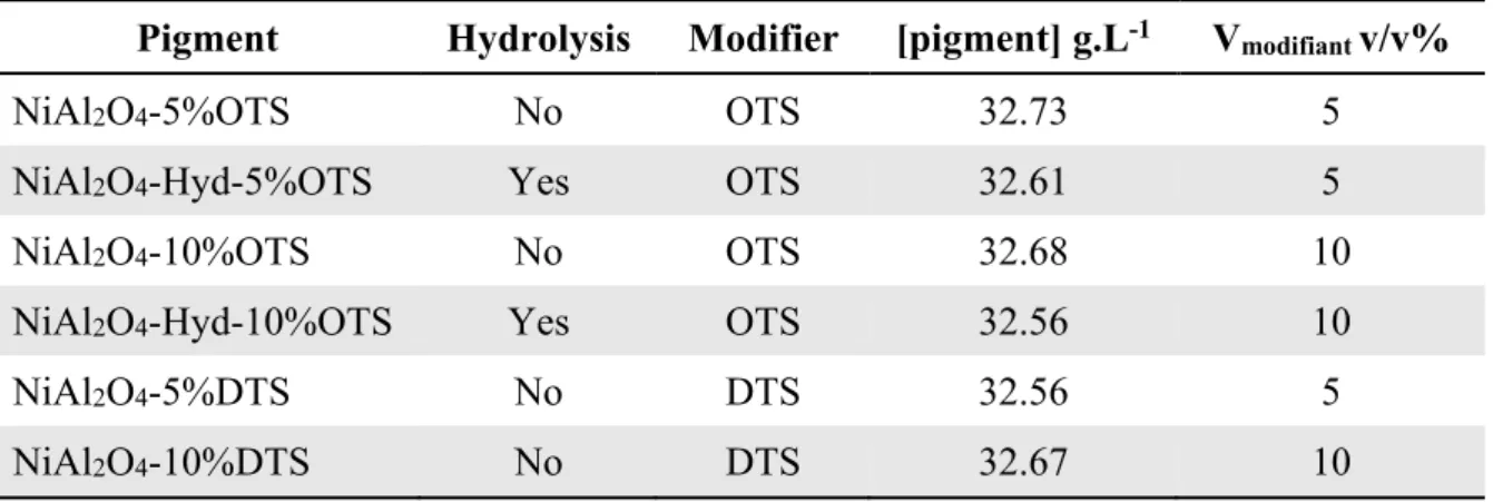
The modification of the inorganic pigments surface was performed to favor their dispersion in non-polar organic media (Isopar G). This preliminary modification is mandatory in order to synthesize hybrid polymer-inorganic particles by dispersion polymerization in Isopar G. The general procedure is schematized in Figure 6. Trimethoxysilane modifiers with different alkyl chains were grafted to the particle surface in order to increase the pigment hydrophobicity. The grafting is achieved via sol-gel chemistry during 20 h in dry toluene at 120°C (Figure 6) and leads to the dispersion of the pigments in non-polar media. Three parameters were studied; (i) the alkyl chain length (with n-Octyltrimethoxysilane OTS or n-Dodecyltrimethoxysilane DTS), (ii) the volume of modifier (10 or 5 v/v%) and (iii) a prior hydrolysis to increase the percentage of hydroxyl groups at the pigment surface. All these modifications are reported in Table 5.
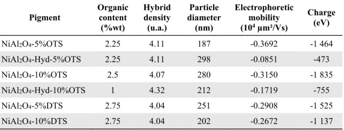
These pigments have been characterized by (i) TGA to obtain the grafting percentage, (ii) DLS to determine the diameter of the hybrid particle, (iii) and Zetametry to evaluate the electrophoretic mobility (Table 2).According to the Table 2, the charge q, which is negative, do not depend on the alkyl chain length of the modifier. A prior hydrolysis does not increase the polymer content, so it is a step which is not necessary. One can observe, that lower the hybrid density, higher the alkyl chain, but it is not dependent on the modifier volume. The modification with DTS will be preferred at this step if we consider that the elaboration of a highly charged pigments with a low
density is predominant for this modification. Figure SI-3 shows pigment without any modification dispersed in apolar media and pigments after silanization. The sedimentation of the pigment is slower after silanization compared to the dispersion of the pigment alone. Because of the low organic content, the density remains high, so the dispersion is still not very stable. It is surprising that the organic content is so low because the pigment exhibits an excess of Al-O(OH) bonds. It could be explained by a small specific surface of the pigment, in regards of the particle shape and its volume/surface ratio. In the following part, polymerization with MMA will be performed on each sample.
Hybrid particles synthesis in isopar G with MMA as a monomer
In order to decrease the density of the inorganic pigments and improve the colloidal stability in organic media, modified inorganic pigments were encapsulated into a polymer shell. As described
in the literature,38 Nitroxide-Mediated Radical Polymerization (NMRP) of methyl methacrylate
(MMA) directly in a non-polar medium, using a poly(lauryl methacrylate) macro-initiator, led to core/shell hybrid particles (the general procedure is schematically represented in Figure 7). Lipophilic macroinitiators, covalently linked to the polymer shell, play the role of steric stabilizers thanks to their compatibility with the dispersing medium (isopar G).
For the dispersion polymerization, the molar mass of the poly(lauryl methacrylate) macro-initiator was fixed at 4500 g.mol-1. We tried to keep the ratio between monomer and macro-initiator around
370, but depending on experimental conditions, it slightly varies between 340 and 400. ( between Different modified pigments were used for the dispersion polymerization: with or without hydrolysis, OTS or DTS as modifying agent with two different feeding quantities (10 or 5 v/v%). Several dispersions in isopar G of hybrid particles have been obtained; Table 3 summarizes the experimental conditions for all of them.
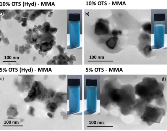
TEM imaging was performed on Ni0.84Al2.11O4 modified with different alkyl chains size and
modifier volume (Figure 8). One can observe a polymer shell around few aggregated pigments (in black) which allows a satisfying dispersion of the pigment particles. These observations were also confirmed by STEM imaging in dark-field mode (Figure SI-4). The electrophoretic mobility and the hydrodynamic radius of particles were determined by Phase Analysis Light Scattering (PALS) and Dynamic Light Scattering (DLS). All the hybrid particles characterizations are summarized in
Table 4.
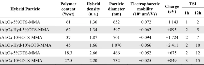
First, we can observe that pigments are positively charged after dispersion polymerization whereas they were negatively charged just after silanization. This can be explained by the use of MMA as
monomer. It was observed that the use of 4-Vinyl Pyridine (4-VP) in non-polar media, leading to
positively charged particles even without charge control agent 8. PMMA could behave in the same
way, in that case. The mechanism is not well understood, but it can be explained by auto-ionization
of solvent or impurities and/or adsorption of ionic species at the surface of PMMA 39. Polymer
content, which is expressed in wt. % and determined by TGA is higher with OTS (smaller alkyl chains) than with the use of DTS (Figure SI-5). Particles average diameter has been determined by DLS. The particle size is two or three times higher after these two steps of surface modification in comparison with the pristine pigment. Those results are also confirmed by TEM pictures where pigments are aggregated inside a polymer shell. The use of DTS leads to low polymer contents. Indeed, as PMMA is a polar polymer, its precipitation around a very hydrophobic particle is more difficult. This could explain why modifications with OTS (which is less hydrophobic than DTS) allow to obtain a better polymer encapsulation. Furthermore, for both OTS and DTS, when a higher amount of silanization agent is used, we obtain low polymer contents and bigger particles. This is characteristic of an increase of inorganic pigment aggregation due to a too hydrophobic interface avoiding the precipitation of PMMA around the pigment. Consequently, the density, determined
from the Equation 3, is lower when a low amount of OTS is used for silanization. The goal is to
obtain a density close to the one of the dispersive medium (Isopar G, d=0.749) to obtain stable particles. A large amount of OTS would be preferred to obtain a higher charged particle (less polymer, more aggregated pigments), but a smaller amount of OTS is preferable to obtain a more stable ink thanks to small density particles.
Finally, we compared hybrid particles obtained with or without a prior hydrolysis. One can see it permits to improve a bit the grafting rate and the hybrid density but it increases the particles diameter and decreases the electrophoretic mobility and the charge. Therefore, this prior step does not allow any improvement of the ink qualities. In summary, a balance between all these parameters characterizations is needed to obtain a stable charged dispersion.
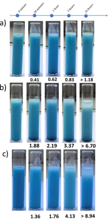
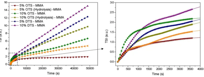
The analysis of the ink stability was performed with Turbiscan® Lab Stability Analyzer. By this way, it is possible to determine an index of sedimentation (TSI) which is specific to the apparatus and which is obtained from Equation 5 (see experimental part). The lower the sedimentation index, the higher stability inks. All results are gathered in Figure 10 and Table 4. Photography of the most stable, an intermediate and the least stable dispersions are presented in Figure 9. As expected, the more stable ink from Ni0.84Al2.11 0.05O4 pigments is obtained when a low quantity
of OTS (5 v/v%) is used as modification agent before the polymerization. This is in correlation with the hybrid particles characterization (Table 4). Indeed, the most stable particles are the ones
with the highest polymer content, the lowest density and the smallest diameter (limiting aggregation). It is interesting to notice that prior pigment hydrolysis does not improve (or degrade) significantly the ink stability. Nevertheless, despite there is partial decantation after 24 hours in the two wort cases, it is important to note that for application a stability of few hours, even few minutes could be enough. Indeed, in an EPID, it is possible to apply regularly an electric field for few milliseconds in order to maintain the image.
Finally, we tried to estimate the capability of re-dispersion after decantation. Figure SI-6 shows the TSI curves obtained immediately after polymerization and after remixing of aged dispersions. In both cases, similar behaviors were observed highlighting the possibility to remix dispersions after sedimentation.
3. CONCLUSION
Cyan NiAl2O4 spinel pigments have been synthesized by a sol-gel route. The preparation of
aluminum over-stoichiometric pigments results in a single phase. The cation distribution of Ni0.84Al2.11 0.05O4 compound inside the spinel crystalline framework has been extracted from
Rietveld refinements using different choices for vacancy location. The refinement quality is only weakly impacted by the vacancy location model. However, as the cationic distribution is significantly impacted by the vacancy location, it is difficult to determine an accurate cation distribution, even if the occurrence of cationic vacancies in octahedral site leads to the lowest reliability factor RB. Nonetheless, in all cases, a distribution of nickel (II) chromophores in both
tetrahedral and octahedral sites is obtained. Considering the structural hypothesis where cations vacancies are located in Oh site, the proportion of Ni2+ in Td and Oh sites for the Ni
0.84Al2.11 0.05O4
composition should be after refinement 46% (Td) : 54% (Oh), close to fifty-fifty corresponding to a partially inverted spinel. This is confirmed from the absorption bands indexed on optical spectra where d-d transitions related to Td (high intensity of the triplet around 650 nm due to the acentric character of Td site) and Oh environments (the lowest intensity bands around 700 nm related to the centrosymmetric Oh site) are clearly visible. This study showed hence the difficulty to control the cyan coloration of such compounds. On the basis of optical spectra, in the series of pure phases with Ni/Al = 0.35, 0.40, 0.45 atomic ratios, the higher the Al content for Ni/Al=0.45 value, the lower the Ni2+ rate in Td site. Whatever Ni/Al molar ratio ranging from 0.3 to 0.4, experimental
colorimetric parameter L*a*b* are very closed to the theoretical ones for the cyan color and this can be related to a higher amount of Ni2+ in Td environment.
Colored and charged electrophoretic inks were successfully synthesized via the encapsulation of the as-prepared inorganic pigments directly in a non-polar medium. NMRP of MMA in the presence of pigments and a hydrophobic macro-initiator leads to the formation of core-shell hybrid particles. The particle charge is dependent on the nature of the pigment surface, i.e. the IEP of the pigment, the type of monomer used and the polymer grafting rate. The use of MMA as monomer induced a change of the hybrid charge from negative to positive. These inks were further formulated without the use of any additive and the study of their stability has shown that the use of OTS as surface modifier OTS inks are adequate for EPID applications.
Further works will consist in mixing those pigments with white negatively charged hybrid particles to produce a dual-colored electrophoretic ink for the next generation of colored EPID.
4. EXPERIMENTAL PART
Pigment synthesis
NiAl2O4 pigments were synthesized by a sol gel process: the Pechini route. This process is based
on cations chelation by citric acid (CA), (Aldrich, ACS reagent > 99.5%) and on polyesterification between CA and ethylene glycol (EG), (Alfa Aesar, purity over 99%) leading to the formation of a polycationic resin. Aqueous solutions of citrate were prepared by dissolving CA and EG in a
minimal volume of water. Then, cationic salts: NiCl2,6H2O (Alfa Aesar, purity over 98%) and
AlCl3,6H2O (Sigma Aldrich, purity 99%) were added in stoichiometric proportion to the acid
solution. CA and EG are in equimolar proportion and the CA/cations molar ratio equals 4:1. EG-CA polymerization was promoted by removing water with continuous heating on a hot plate. The as-prepared highly viscous mixtures were thermally treated in two steps: a first calcination at 400°C under air to remove organics components, then, an annealing step for 10 hours at 1400°C. Pigment functionalization
As a representative experiment, a 100 ml two necked flask was used and 326 mg of inorganic pigments were dispersed in 10 mL of dried toluene. The mixture was sonicated for 30 minutes in an ultrasonic bath and heated at 120°C for 18 hours under magnetic stirring; 10 or 5 v/v% of OTS n-octyltrimethoxysilane, (OTS), (ABCR, 97%) or n-dodecyltrimethoxysilane (DTS), (TCI, 93%) was added to the mixture. The dispersion reaction was washed by centrifugation/redispersion cycles in dried toluene. The modified pigments were then dried at 65°C for one-night long. Table
5 summarizes the experimental conditions used for these pigment modifications. Optionally, a
preliminary hydrolysis step was performed to observe an eventual impact of surface hydroxyl groups on the pigment modification process. For this, in a 100 mL two necked flask 1 g of pigment
are dispersed into 5 g of hydrogen peroxide (30%). The mixture was sonicated during 30 minutes and heated at 105°C during 4 hours. The dispersion reaction was washed by centrifugation/redispersion cycles in deionized water. The resulting powder was dried for few hours in a vacuum oven.
Hybrid particles synthesis
For a typical Nitroxide Mediated Radical Polymerization (NMRP) via dispersion in Isopar G
(commercial isoparaffinic hydrocarbon, Exxon Mobil Chemical), 5.0×10⁻⁴ mol of lauryl acrylate-
SG1 macroinitiator 40 and 200 mg of the modified pigments were firstly dispersed in 10 mL
Isoparaffin G. This solution was ultra-sonicated during 1 hour. Then the solution was outgassed by bubbling argon for 1 additional hour; this step including the addition of Methyl methacrylate (MMA), (Acros 99%) after 30 minutes of nitrogen bubbling. Finally, the mixture was heated at 120°C under mechanical stirring for 19 hours. Finally, the prepared particle suspension (i.e. as-prepared electrophoretic ink) was cooled down and purified by 3 cycles of centrifugation and redispersion in Isoparaffin G to remove the residual monomers.
Characterization techniques
X-Ray diffraction (XRD) measurements were carried out on a PANalytical X’PERT PRO diffractometer equipped with an X-celerator detector, using Cu(K)radiation. The spectra
were recorded on 5-120° 2ϴ range with a time per step chosen in order to get at least 10,000 cps in intensity for the main diffractogram peak. Diffractograms were refined with the Rietveld refinement method using FULLPROF® program package. The unit-cell parameters, the atomic positions, the cationic distribution (cation inversion parameter) were then refined (with fixed Debye Waller factors) on the basis of the Fd-3m space group corresponding to the spinel structure. The peak profiles are fitted with the Caglioti function, i.e. considering isotropic crystallites. Uncertainties can be calculated from the standard deviation proposed by the software; these uncertainties being approximated in all cases to the decade higher, all reported results are limited to their last significant digit.
UV-Vis-NIR diffuse reflectivity (R(λ)%) spectra – herein, presented after Kubelka-Munk
transformation: KM(λ) = (1- R(λ)%)2/(2R(λ)%), - were recorded at room temperature from 200
to 2500 nm with a step of 1 nm and a band length of 2 nm on a Cary 17 spectrophotometer using an integration sphere. Halon polymer was used as white reference for the blank. A mathematic treatment of the obtained spectra allowed the determination of the L*a*b* space colorimetric parameters. The first step of the treatment consists in obtaining the XYZ tri-stimulus values
(defined by the CIE, 1964) from the integration (on the visible range, i.e. from λ = 380 nm up to 780 nm) of the product of x(λ), y(λ) or z(λ) functions (CIE – 1964) with the diffuse reflectance spectra function: X = ∫ x(λ). R(λ)d λ. Then, the transfer equations defined by the CIE, 1976, from XYZ space to the L*a*b* space, were used in order to obtain the L*a*b* chromatic parameters.
The morphology of Ni1-xAl2+2x/3O4 nanoparticles was evaluated by transmission electronic
microscopy (TEM). These characterizations were performed on TEM Jeol 2100F operated at 200
kV with a LaB6 gun. The theoretical resolution (FWHM) was nominally 2.3 Å. The quantification
of Ni and Al concentration were performed by Energy Dispersive X-Ray Spectrometry (EDX) considering K lines intensities and integration. Samples were prepared by dissolving a few milligrams of powder in ethanol directly depositing one drop of the as-prepared suspension on a copper grid.
Hybrid particles were first imaged by transmission electron microscopy (TEM) using a JEOL
1400+ at 120kV equipped with a LaB6 filament and a GATAN camera with condenser diaphragm.
STEM observations were carried out on a JEOL 7800 using an acceleration voltage of 15 kV and the transmission electron detector (TED) in dark-field mode.
Thermogravimetric analyses (TGA) from 20°C to 700°C at 10°C.min-1 were performed under
nitrogen environment with a Q500 apparatus from TA Instrument.
The density of the as-prepared hybrid particles was estimated according to the pigment density (ρpig) and the polymer density (ρpol) reported from the literature using the weight fractions of the
pigment, 𝑤𝑐 , and the polymer, 𝑤𝑐 , deduced from the thermal gravimetric analysis (see
Equation 3) [5]. 𝜌 𝑤𝑐 1 𝜌 𝑤𝑐 𝜌 Equation 3
The electrophoretic mobility and the hydrodynamic radius of colloids were determined by Phase Analysis Light Scattering (PALS) and Dynamic Light Scattering (DLS), respectively, on a Nano ZS Malvern Instrument using a wavelength of λ = 633 nm at a fixed angle θ=90°. A square shaped
wave electric field from 2.5 to 20 kV.m-1 was applied using a dip cell designed for measurement
in a non-aqueous environment. Each sample was measured 3 times (15 runs/measurement). The q global charge of hybrid particles was determined using the equation reported by Fang and
potential (V), R: the average radius of the particles; g: 9.8m.s-2; η: the viscosity of the
electrophoretic medium in mPa.s).
𝜈 Equation 4
Stability of the inks was estimated using a Turbiscan® lab stability analyzer in order to follow the stability of the colloidal dispersions over time using the transmittance and backscattering ratio of a pulsed near infrared light (λ = 880 nm). The transmittance detector received the light which passed through the dispersion at an angle of 180° with the respect to the source, while the backscattering detector received the light scattered backward by the dispersion at an angle of 45°. The analysis of the stability was carried out as a variation of backscattering (BS) and transmittance (T%) profiles. Equation 5 is used for the calculation of the Turbiscan Stability Index (TSI). TSI is obtained by analyzing the evolution versus time of evolution of the transmission of each suspension layer (at different height: h), and normalizing the result by the total analyzed thickness (H) in order to obtain a result which is independent of the quantity of sample in the measuring tube.
𝑇𝑆𝐼 𝑡𝑢𝑟𝑏𝑖𝑠𝑐𝑎𝑛 𝑠𝑡𝑎𝑏𝑖𝑙𝑖𝑡𝑦 𝑖𝑛𝑑𝑒𝑥
∑ |𝑇% ℎ 𝑇% ℎ |
𝐻
Equation 5
FIGURES
Figure 1. XRD patterns of NiAl2+xO4+ compounds (with Ni/Al =0.5, 0.45, 0.4, 0.35, 0.3 or 0.25)
prepared from Pechini route followed by post-annealing at 1400°C. Al2O3 (*) and NiO (♦)
impurities are shown.
Figure 2. Evolution of the cell parameter of the main spinel phase in the Ni1-xAl2+2x/3O4
compounds; weight percentage of each phases (NiAl2O4, NiO and Al2O3) within the NiAl2+xO4+
Figure 3. TEM micrographs of Ni1-xAl2+2x/3O4 samples with Ni/Al theoretical ratio equal to 0.40
(left side) and 0.25 (central to right side with different zone area and magnificence).
Figure 4. a) L*a*b* colour parameters and b) K/S spectra of Ni1-xAl2+2x/3O4 compounds (with
Ni/Al =0.5, 0.45, 0.4, 0.35, 0.3 or 0.25). Transitions corresponding to nickel (II) in octahedral (blue) and tetrahedral (green) coordination are identified.
Figure 5. a)Evolution of the optical contrast and b) Diffuse reflectance spectra ofNi1-xAl2+2x/3O4
(A) pigment and of mixtures with 50 wt.% of CaCO3 (α), Al2O3 (β) and TiO2 (γ).
Figure 7. Hybrid particles synthesis via NMRP in isopar G as a solvent
Figure 8. TEM micrographs of Ni0.84Al2.11 0.05O4 hybrid. a) Hydrolysed, modified with 10 v/v%
of OTS and polymerised with 10 v/v% of MMA, b) Modified with 10 v/v% of OTS and polymerised with 10 v/v% of MMA c) Hydrolysed, modified with 5 v/v% of OTS and polymerised with 10 v/v% of MMA d) Modified with 5 v/v% of OTS and polymerised with 10 v/v% of MMA
Figure 9. Pictures of samples as function of time of three disperisons of hybrid particles
polymerised with 10 v/v% of MMA and dispersed in Isopar-G, a) Modified with 5 v/v% of OTS, b) Modified with 10 v/v% of OTS and c) Modified with 10v/v% of DTS. TSI are indexed in each picture.
Figure 10. Evolution of the Time Sedimentation Index (TSI) with the time for hybrid particles
TABLES
Table 1. Occupancy rate and correlation factors issued from three kinds of Rietveld refinement.
(If there is no vacancy, if the vacancy is in an octahedral or in a tetrahedral site).
Atom Occupancy rate / NiAl2O4 Occupancy rate / vacancy [6] Occupancy rate / vacancy [4]
Ni [4] 0.007 0.016 0.023 Ni [6] 0.034 0.019 0.012 Al [4] 0.034 0.025 0.016 Al [6] 0.049 0.062 0.072 RB 2.78 1.89 2.12 Rp 10.9 10.4 10.6
Composition (Ni0.18Al0.82)[Ni0.82Al1.18]O4 (Ni0.39Al0.61)[Ni0.45Al1.50 0.05]O4 (Ni0.56Al0.39 0.05)[Ni0.29Al1.71]O4
Table 2. Characterization of the modified inorganic pigments: organic content, diameter,
electrophoretic mobility, density and charge in Isopar G
Pigment Organic content (%wt) Hybrid density (u.a.) Particle diameter (nm) Electrophoretic mobility (104 µm²/Vs) Charge (eV) NiAl2O4-5%OTS 2.25 4.11 187 -0.3692 -1 464 NiAl2O4-Hyd-5%OTS 2.25 4.11 298 -0.0851 -473 NiAl2O4-10%OTS 2.5 4.07 280 -0.3150 -1 835 NiAl2O4-Hyd-10%OTS 1 4.32 212 -0.1719 -755 NiAl2O4-5%DTS 2.75 4.04 251 -0.2908 -1 525 NiAl2O4-10%DTS 2.75 4.04 202 -0.2672 -1 137
Table 3. Experimental conditions of hybrid particles syntheses via NMRP polymerization with
MMA as monomer and polylaurylacrylate as macroinitiator (Mn = 4500 g/mol) in isopar G, on previously modified pigments.
Hybrid Particle [pigment]
g.L-1 (mmol.L[Ma(LA)] -1 ) (mol.L[MMA] -1)
𝒎𝒐𝒏𝒐𝒎𝒆𝒓 𝒎𝒂𝒄𝒓𝒐𝒊𝒏𝒊𝒕𝒊𝒂𝒕𝒐𝒓 NiAl2O4-5%OTS-MMA 19.91 2.72 0.94 334 NiAl2O4-Hyd-5%OTS-MMA 19.96 2.41 0.94 378 NiAl2O4-10%OTS-MMA 20.31 2.53 0.94 360 NiAl2O4-Hyd-10%OTS-MMA 19.96 2.24 0.94 406 NiAl2O4-5%DTS-MMA 20.45 2.40 0.94 379 NiAl2O4-10%DTS-MMA 21.30 2.60 0.94 350
Table 4. Characterization of hybrid particles obtained via NMR polymerization with MMA on
inorganic pigments.
Hybrid Particle Polymer content (%wt) Hybrid density (u.a.) Particle diameter (nm) Electrophoretic mobility (104 µm²/Vs) Charge (eV) TSI 1h 12h NiAl2O4-5%OTS-MMA 61 1.36 652 +0.072 +1 143 1 2 NiAl2O4-Hyd-5%OTS-MMA 62 1.34 597 +0.062 +895 2 5 NiAl2O4-10%OTS-MMA 37 1.87 701 +0.094 +1 724 2 7 NiAl2O4-Hyd-10%OTS-MMA 45 1.66 1 070 +0.066 +2 411 2 10 NiAl2O4-5%DTS-MMA 18.3 2.66 466 +0.052 +675 2 12 NiAl2O4-10%DTS-MMA 27.5 2.20 732 +0.025 +849 3 15
Table 5. Experimental conditions for pigment modification.
Pigment Hydrolysis Modifier [pigment] g.L-1 V
modifiant v/v%
NiAl2O4-5%OTS No OTS 32.73 5
NiAl2O4-Hyd-5%OTS Yes OTS 32.61 5
NiAl2O4-10%OTS No OTS 32.68 10
NiAl2O4-Hyd-10%OTS Yes OTS 32.56 10
NiAl2O4-5%DTS No DTS 32.56 5
NiAl2O4-10%DTS No DTS 32.67 10
ASSOCIATED CONTENT Supporting Information.
Rietveld refinement, isoelectric point determination, STEM blackfield images, TGA curves and evolution of the time sedimentation index of the inks.
The Supporting Information is available free of charge on the ACS Publications website at
http://pubs.acs.org.
AUTHOR INFORMATION Corresponding Author
*Corresponding authors : cyril.brochon@enscbp.fr and manuel.gaudon@icmcb.cnrs.fr
Author Contributions
The manuscript was written through contributions of all authors.
ACKNOWLEDGMENT Authors want to thank Equipex ELORPrintTec facilities (ANR‐10‐EQPX‐28‐01)
REFERENCES
[1] Comiskey, B.; Albert, J.; Yoshizawa, H.; Jacobson, J. An electrophoretic ink for all-printed reflective electronic displays. Nature. 1998, 394, 6690, 253–255.
[2] Rogers, J. A.; Bao, Z. Printed plastic electronics and paperlike displays. J. Polym. Sci. Part
Polym. Chem. 2002, 40, 20, 3327–3334.
[3] Kim, C. A.; Joung, M. J.; Ahn, S. D.; Kim, G. H.; Kang, S.-Y.; You, I.-K.; Oh, J.; Myoung, H. J.; Baek, K. H.; Suh. K. S.; Microcapsules as an electronic ink to fabricate color electrophoretic displays. Synth. Met. 2005, 151, 3, 181–185.
[4] Badila, M.; Hébraud, A.; Brochon, C.; Hadziioannou, G. Design of Colored Multilayered Electrophoretic Particles for Electronic Inks. ACS Appl. Mater. Interfaces. 2011, 3, 9, 3602–3610.
[5] Yu, D.-G.; An, J. H. Preparation and characterization of titanium dioxide core/polymer shell hybrid composite particles prepared by emulsion polymerization. J. Appl. Polym. Sci.
2004, 92, 5, 2970–2975.
[6] Fang, Y.; Wang, J.; Li, L.; Liu, Z.; Jin, P.; Tang. C. Preparation of chromatic composite hollow nanoparticles containing mixed metal oxides for full-color electrophoretic displays.
J. Mater. Chem. C. 2016, 4, 24, 5664–5670.
[7] Peng, B.; Li, Y.; Li, J.; Lu, H.; Xie, J.; Ren, X.; Cao, Y.; Wang, N.; Meng, X.; Deng, L.; Guo, Z. Monodisperse light color nanoparticle ink toward chromatic electrophoretic displays. Nanoscale. 2016, 8, 21, 10917–10921.
[8] Noël, A.; Mirbel, D.; Charbonnier, A.; Cloutet, E.; Hadziioannou, G.; Brochon, C.
Synthesis of charged hybrid particles via dispersion polymerization in nonpolar media for color electrophoretic display application. J. Polym. Sci. Part Polym. Chem. 2017, 55, 2, 338–348.
[9] Yu, D.-G.; An, J. H.; Bae, J.-Y.; Ahn, S. D.; Kang, S.-Y.; Suh, K.-S. Negatively Charged Ultrafine Black Particles of P(MMA- c o -EGDMA) by Dispersion Polymerization for Electrophoretic Displays. Macromolecules. 2005, 38, 17, 7485–7491.
[10] Wen, T.; Meng, X.; Li, Z.; Ren, J.; Tang, F. Pigment-based tricolor ink particles via mini-emulsion polymerization for chromatic electrophoretic displays. J. Mater. Chem. 2010, 20,
37, 8112.
[11] Werts, M. P. L.; Badila, M.; Brochon, C.; Hebraud, A.; Hadziioannou, G. Titanium Dioxide- Polymer Core–Shell Particles Dispersions as Electronic Inks for Electrophoretic Displays. Chem. Mater. 2008, 20, 4, 1292–1298.
[12] Regan, M. T. Novel phthalocyanine pigments.1983.
[13] El Jazouli, A.; Tbib, B.; Demourgues, A.; Gaudon, M. Structure and colour of diphosphate pigments with square pyramid environment around chromophore ions (Co2+, Ni2+, Cu2+).
Dyes Pigments. 2014, 104, 67–74.
[14] Robertson, L.; Duttine, M.; Gaudon, M.; Demourgues, A. Cobalt–Zinc Molybdates as New
Blue Pigments Involving Co2+ in Distorted Trigonal Bipyramids and Octahedra. Chem.
Mater. 2011, 23, 9, 2419–2427.
[15] Giannakas, A. E.; Ladavos, A. K.; Armatas, G. S.; Pomonis, P. J. Surface properties, textural features and catalytic performance for NO + CO abatement of spinels MAl2O4 (M
= Mg, Co and Zn) developed by reverse and bicontinuous microemulsion method. Appl.
Surf. Sci. 2007, 253, 16, 6969–6979.
[16] Sickafus, K. E.; Wills, J. M.; Grimes, N. W. Structure of spinel. J. Am. Ceram. Soc. 1999, 82,12, 3279–3292.
[17] Areán, C. O.; Mentruit, M. P.; López, A. L.; Parra, J. B. High surface area nickel aluminate spinels prepared by a sol–gel method. Colloids Surf. Physicochem. Eng. Asp. 2001, 180, 3, 253–258.
[18] Bayal, N.; Jeevanandam, P. Synthesis of CuO@NiO core-shell nanoparticles by homogeneous precipitation method. J. Alloys Compd. 2012, 537, 232–241.
[19] Li, C. Y.; Zhang, H. J.; Chen, Z. Q. Reaction between NiO and Al2O3 in NiO/γ-Al2O3
catalysts probed by positronium atom. Appl. Surf. Sci. 2002, 266, 17–21.
[20] Amini, M. M.; Torkian, L. Preparation of nickel aluminate spinel by microwave heating.
Mater. Lett. 2002, 57, 3, 639–642.
[21] Peelamedu, R. D.; Roy, R.; Agrawal, D. K. Microware-induced reaction sintering of NiAl2O4. Mater. Lett. 2002, 55, 234–240.
[22] Jeevanandam, P.; Koltypin, Y.; Gedanken, A. Preparation of nanosized nickel aluminate spinel by a sonochemical method. Mater. Sci. Eng. B. 2002, 90, 125–132.
[23] Gama, L.; Ribeiro, M. A.; Barros, B. S.; Kiminami, R. H. A.; Weber, I. T.; Costa, A. C. F. M. Synthesis and characterization of the NiAl2O4, CoAl2O4 and ZnAl2O4 spinels by the
polymeric precursors method. J. Alloys Compd. 2009, 483, 1–2, 453–455. [24] Suciu, C.; Patron, L.; Mindru, I.; Carp, O. Nickel aluminate spinel by thermal
decomposition of polynuclear malate complexes. Rev. Roum. Chim. 2006, 51, 5, 385. [25] Nazemi, M. K.; Sheibani, S.; Rashchi, F.; Gonzalez-DelaCruz, V. M.; Caballero, A.
Preparation of nanostructured nickel aluminate spinel powder from spent NiO/Al2O3
catalyst by mechano-chemical synthesis. Adv. Powder Technol. 2012, 23, 6, 833–838. [26] Ribeiro, N. F. P.; Neto, R. C. R.; Moya, S. F.; Souza, M. M. V. M.; Schmal, M. Synthesis
of NiAl2O4 with high surface area as precursor of Ni nanoparticles for hydrogen production.
Int. J. Hydrog. Energy. 2010, 35, 21, 11725–11732.
[27] Leal, E.; De Melo Costa, A. C. F.; De Freita, N. L.; De Lucena Lira, H.; Kiminami, R. H. G. A.; Gama, L. NiAl2O4 catalysts prepared by combustion reaction using glycine as fuel.
Mater. Res. Bull. 2011, 46, 9, 1409–1413.
[28] Cooley, R. F.; Reed, J. S. Equilibrium cation distribution in NiAl2O4, CuAl2O4, and
ZnAl2O4 spinels. J. Am. Ceram. Soc. 1972, 55, 8, 395–398.
[29] Han, Y. S.; Li, J. B.; Ning, X. S.; Yang, X. Z.; Chi, B. Study on NiO excess in preparing NiAl2O4. Mater. Sci. Eng. A. 2004, 369, 1–2, 241–244.
[30] Subramanian, R.; Higuchi, M.; Dieckman, R. Growth of nickel aluminate single crystals by the floating zone method. J. Cryst. Growth. 1994, 143, 3–4, 311–316.
[31] Zhou, R.-S.; Snyder, R. L. Structures and transformation mechanisms of the η, γ and β transition aluminas. Acta Crystallogr. B. 1991, 47, 5, 617–630.
[32] Smrcok, L.; Langer, V.; Krestan, J. γ-Alumina: a single-crystal X-ray diffraction study.
Acta Crystallogr. C. 2006, 62, 9, 83–84.
[33] Tanabe, Y.; Sugano, S. On the absorption spectra of complex ions I. J. Phys. Soc. Jpn.
1954, 9, 5, 753–766.
[34] Tanabe, Y.; Sugano, S. On the absorption spectra of complex ions II. J. Phys. Soc. Jpn.
1954, 9, 5, 766–779.
[35] Tanabe, Y.; Sugano, S. On the absorption spectra of complex ions III. J. Phys. Soc.
Jpn.1956, 11, 8, 864–877.
[36] Tanabe, Y.; Kamimura, H. On the absorption spectra of complex ions IV. J. Phys. Soc.
Jpn.1958, 13, 4, 394–411.
[37] Tilley, R. Colour and optical properties of materials, Wiley; 2000.
[38] Charbonnier, A.; Brochon, C.; Cloutet, E.; Navarro, C.; Hadziioannou, G. Synthesis of functional polymer particles by dispersion polymerization in organic media: A tool toward stable electrophoretic inks. J. Polym. Sci. Part Polym. Chem. 2013, 51, 21, 4608-4616. [39] Smith, G.N.; Hallett, J.E.; Easto, J. Soft Matter. 2015, 11, 8029-8041
[40] Noel, A.; Mirbel, D.; Cloutet, E.; Fleury, G.; Schatz, C.; Navarro, C.; Hadziioannou, G.; Brochon, C. Tridodecylamine, an efficient charge control agent in non-polar media for electrophoretic inks application. Appl. Surf. Sci. 2018, 428, 870–876.