HAL Id: hal-01731291
https://hal.archives-ouvertes.fr/hal-01731291
Submitted on 6 May 2019HAL is a multi-disciplinary open access
archive for the deposit and dissemination of sci-entific research documents, whether they are pub-lished or not. The documents may come from teaching and research institutions in France or abroad, or from public or private research centers.
L’archive ouverte pluridisciplinaire HAL, est destinée au dépôt et à la diffusion de documents scientifiques de niveau recherche, publiés ou non, émanant des établissements d’enseignement et de recherche français ou étrangers, des laboratoires publics ou privés.
O2 Reduction in Enzymatic Biofuel Cells
Nicolas Mano, Anne de Poulpiquet
To cite this version:
Nicolas Mano, Anne de Poulpiquet. O2 Reduction in Enzymatic Biofuel Cells. Chemical Reviews, American Chemical Society, 2018, 118 (5), pp.2392 - 2468. �10.1021/acs.chemrev.7b00220�. �hal-01731291�
1
O
2Reduction in Enzymatic Biofuel cells
Nicolas Mano
a,b,*and Anne de Poulpiquet
c, a CNRS, CRPP, UPR 8641, 33600 Pessac, FrancebUniv. Bordeaux, CRPP, UPR 8641, 33600 Pessac, France
*mano@crpp-bordeaux.cnrs.fr
c Bioénergétique et Ingénierie des Protéines, CNRS-AMU, 31, chemin Aiguier, 13009
Marseille, France
both authors contibuted equally to this work
Abstract
Catalytic four-electron reduction of O2 to water is one of the most extensively studied
electrochemical reactions due to O2 exceptional availability and high O2/H2O redox potential,
which may in particular allow highly energetic reactions in fuel cells. To circumvent the use of expensive and inEfficient Pt catalysts, multicopper oxidases (MCOs) have been envisioned because they provide Efficient O2 reduction with almost no overpotential. MCOs have been
used to elaborate enzymatic biofuel cells (EBFCs), a sub-class of fuel cells in which enzymes replace the conventional catalysts. A glucose/O2 EBFC, with a glucose oxidizing anode and a
O2 reducing MCO cathode, could become the in vivo source of electricity that would power
sometimes in the future integrated medical devices. This review covers the challenges and advances in the electrochemistry of MCOs and their use in EBFCs with a particular emphasis in the last 6 years. First basic features of MCOs and EBFCs are presented. Clues provided by electrochemistry to understand these enzymes, and how they behave once connected at electrodes, are described. Progresses realized in the development of Efficient biocathodes for O2 reduction relying both on direct and mediated electron transfer mechanism are then
2 CONTENTS Symbols 4 1. Introduction 8 2. Background 12 2.1 Multicopper oxidases 12 2.1.1 Laccases 15 2.1.2 Bilirubin oxidases 17
2.1.3 Cuprous oxidase and tyrosinase 18
2.2 Basic features of enzymatic biofuel cells 19 2.3 Electronic connection of immobilized enzymes 23
3. Mechanistic studies of MCOs 26
3.1 Effect of pH on MCOs 28
3.2 Halides inhibition 30
3.3 Model of mediated electron transfer 33
3.3.1 Model 33
3.3.2 Mathematical modeling 36
3.4 Studies of the mechanism of direct electron transfer 41
3.4.1 Redox potentials of the Cu sites 41
3.4.2 Non-catalytic faradaic processes under anaerobic conditions 42 3.4.3 Two-versus four-electron reduction of dioxygen 48 3.4.4 Causes of the low catalytic efficiency and stability on gold
electrodes 51
3.4.5 Catalytic mechanism on carbon electrodes 56 3.4.6 Possibility of endergonic electron-transfer 60 3.4.7 Mathematical modeling of the catalytic current 62
3.4.8 Resting forms of MCOs 68
3.4.9 Halides affecting the direct electron transfer 70 3.4.10 Rate limiting steps of O2 reduction 71
3.4.11 Inhibition by H2O2 72
3.4.12 Effect of methanol 74
4. Enzymatic O2 reduction 75
4.1 Direct electron transfer 75
4.1.1 Planar electrodes 76
4.1.2 Carbon nanostructures 81
4.1.3 Gold nanostructures 102
4.1.4 Tailored orientation of MCOs at the electrode interface 111
4.1.5 Stability issues 125
4.2 Mediated electron transfer 133
4.2.1 Bare electrodes 133
4.2.2 Carbon electrodes 145
4.2.3 3D materials 147
3
4.2.5 Other enzymatic systems 156
5. MCOs based biocathodes in enzymatic biofuel cells 162
5.1 Glucose/O2 EBFCs 163
5.1.1 Operated in buffer 163
5.1.2 In fruits/vegetables 164
5.1.3 In vertebrates and invertebrates 165
5.1.4 In serum and blood 166
5.2 H2/O2 EBFCs 169
5.3 Microfluidic biofuel cells 170
5.4 Paper based EBFCs 171
5.5 MCOs with air-breathing electrodes 172
5.6 Biofuel cells for self-powered devices 173
5.7 Hybrid bio-devices 174
5.8 Wearable biofuel cells 177
6. Conclusions and Outlook 178
7. Acknowledgments 180
4 Symbols
ABTS: 2,2'-azinobis(3-ethylbenzothiazolin-6-sulfonate) AFM: Atomic force microscopy
AMT: 4-aminothiophenol AR: Alternative resting AuNPs: Gold nanoparticles BDD: Boron doped diamond
BET: Specific surface area determined by the method of Brunauer, Emmett and Teller BOD: Bilirubin oxidase
BP: Buckypaper
Bp-BOD: Bilirubin oxidase from Bacillus pumilus Bs-BOD: Bilirubin oxidase from Bacillus subtilis
CA: Chronoamperometry CFCs: Conventional fuel cells
Cf-laccase: Laccase from Cerrena fulvocinerea Cm-laccase: Laccase from Cerrena maxima
CNFs: Carbon nanofibers CNPs: Carbon nanoparticles CNTs: Carbon nanotubes CueO: Copper efflux oxidase
Cu-laccase: Laccase from Cerrena unicolor
COx: Cytochrome oxidase CV: Cyclic voltammetry
CVD: Chemical vapor deposition CMF: Carbon microfiber
Cyt c: Cytochrome c
DET: Direct electron transfer DFT: Density functional theory DMP: 2,6-dimethoxyphenol DNA: Desoxyribo nucleic acid
DPI: Dual polarization interferometry EBFCs: Enzymatic biofuel cells
5 EC: Enzyme class
ECR: Electron cyclotron resonance EDX: Energy dispersive X-ray analysis EPR: Electron paramagnetic resonance ESSA: Electroactive specific surface area ET: Electron transfer
FAD: Flavin adenine dinucleotide FDH: Fructose Dehydrogenase
Fp-laccase: Laccase from Fusarium proliferatum
GA: Glutaraldehyde GC: Glassy Carbon
GDH: Glucose dehydrogenase GDL: Gas diffusion layer GO: Graphene oxide GOx: Glucose oxidase Hase: Hydrogenase
HET: Heterogeneous electron transfer HOPG: Highly oriented pyrolytic graphite HRP: Horseradish peroxidase
IET: Internal electron transfer KB: Ketjen black
LDG: Low density graphite LED: Light emitting diode
LMCOs: Laccase-like Multicopper Oxidases LSV: Linear sweep voltammetry
Ma-Laccase: Laccase from Melanocarpus albomyces
MCOs: Multicopper oxidases MET: Mediated electron transfer
MgOC: Magnesium oxide template mesoporous carbon MHA: Mercapto-hexanoic acid
Mo-BOD: Bilirubin oxidase from Magnaporthae orizae
MPA: Mercapto-propionic acid
Mv-BOD: Bilirubin oxidase from Myrothecium verrucaria
6 NAD+: Nicotinamide adenine dinucleotide
NHE: Normal hydrogen electrode NHS: N-Hydroxysuccinimide NI: Native intermediate OCP: Open circuit potential OCV: Open circuit voltage PAA: Polyacrylamide PAMAM: Polyamidoamine PBS: Phosphate buffered saline
PBSE: Pyrene butyric succinimidyl ester
Pc-laccase: Laccase from Pycnoporus cinnabarinus
PDB: Protein data bank PDMS: Polydimethylsiloxane PFC: Plastic formed carbon PG: Pyrolytic graphite PI: Peroxide intermediate PLA: Polylactic acid PLL: Poly-L-lysine
PM-IRRAS: Polarization modulated infra-red spectroscopy PPO: Polyphenol oxidase
PPY: Polypyrrole
PQQ: Pyrroloquinoline quinone PSS : Polystyrene sulfonate PVDF: Polyvinylidene fluoride PVI: Poly(N-vinylimidazole) QCM: Quartz crystal microbalance
QCM-D: Quartz crystal microbalance with dissipation monitoring QM/MM: Quantum mechanical and molecular mechanics
RO: Resting oxidized
RRDE: Rotating ring disc electrode RVC: Reticulated vitreous carbon
Rv-laccase: Laccase from Rhus vernicifera
SAMs: Self-assembled monolayer
7 SECM: Scanning electrochemical microscopy
SERS: Surface enhanced Raman spectroscopy SGZ: Syringaldazine
SPG: Spectroscopic graphite SPR: Surface plasmon resonance STM: Scanning tunneling microscopy SW-CNTs: Single-wall carbon nanotubes SWV: Square wave voltammetry
Ta-laccase: Laccase from Trichaptum abietinum
TBAB: Tetrabutylammonium ions TNC: Tri-nuclear copper cluster
To-laccase: Laccase from Trametes ochracea
TMOS: Tetramethyl orthosilicate
Tt-BOD: Bilirubin oxidase from Trachyderma tsunodae Tt-laccase: Laccase from Trametes troggii
Th-laccase: Laccase from Trametes hirsuta
tVA: Thiolated veratric acid
Tv-laccase: Laccase from Trametes versicolor
8 1. Introduction
About 2.5 billion years ago, oxygen became an important component of the earth atmosphere1 due to the emergence of cyanobacteria, organisms that produce oxygen during
photosynthesis. One of the consequences of this event is the biological utilization of copper, a transition metal now omnipresent in biology, while only iron used to be predominant in the first living forms. In the oceans, oxygenation led to a shift from high-iron to high-copper contents, because oxygen favors the oxidation state +III of insoluble Fe3+, while Cu is
preferentially in the Cu2+ form which is soluble and therefore bioavailable.2 In living
organisms, copper is still linked with oxygen metabolism : a recent study examining copper utilization by 450 bacteria demonstrated that around 80% of anaerobes did not depend on copper, while more than 90% of aerobes were copper dependent.3
Copper can be found in numerous metallo-proteins, in which the metal is coordinated by amino-acids. Copper-containing proteins are present in bacterial, fungal, plant and mammalian organisms.4 In some of the proteins, copper is frozen in the reduced or oxidized
state. Of particular importance in the frame of electrochemistry are the proteins in which copper centers are able to undergo the redox Cu2+/Cu+ reaction. These metallo-proteins
contain either one or several copper centers, and the latter are either mononuclear (type T1, T2 or CuB sites) or binuclear (type T3 or CuA sites).5 Copper ligands and protein environment
modulate the potentials of the +II/+I transition that varies accordingly from 85 mV to >1000 mV,6 while in water the apparent standard potential E°’ of the Cu2+/Cu+ couple is 150 mV vs.
the normal hydrogen reference electrode (NHE).7
Copper-containing proteins cover different functions ranging from electron transfer to catalysis, and are involved in a wide variety of mechanisms among which the most important are energy conversions in respiration or metabolism. It must be noted however that copper is also toxic at high concentrations so that many proteins are linked to copper regulation and
9 homeostasis.2 Copper based enzymes are associated with the metabolism of N2O (nitrous
oxide reductase), NO2- (nitrite reductases), O2.- (superoxide dismutase), or O2.5 More relevant
are the two classes of enzymes involved in oxygen reduction: terminal oxidases, and multi-copper oxidases (MCOs). Terminal oxidases can be divided in cytochrome or quinol oxidases, and contain both copper centers and hemes. Oxygen reduction occurs with cytochrome or reduced quinone as a primary electron donor. The reaction is coupled to proton transfer and the enzyme-catalyzed reactions create the proton gradient necessary for ATP synthesis.8
MCOs catalyze the 4-e- oxygen reduction coupled to oxidation of various organic or metallic
substrates.5 In MCOs, inner sphere electron transfers are involved in binding, activation and
reduction of O2.
Among the desperately sought, but rarely well-engineered devices envisioned for sustainable energy conversion, fuel cells could harvest energy from fuels like dihydrogen, alcohols, etc.9,10 Their advantages stem from direct conversion of chemical energy into
electricity, and long-term operation enabled by continuous fueling. The reaction involved in fuel cells requires a combustive, and O2 is the most widely used because of its availability and
high O2/H2O redox potential.11 Designing catalysts for O2 reduction in conventional fuel cells
(CFCs) is challenging. They generally require high overpotentials,12 or only catalyze the
incomplete O2 reduction to H2O2.13,14 Ideally, the platinum-based catalysts widely used in
CFCs would be replaced by less expensive biological oxidation catalysts. Enzymatic biofuel cells (EBFCs) are a sub-class of fuel cells in which enzymes replace the conventional catalysts used in CFCs. They offer numerous advantages such as selectivity and specificity, allowing in particular operating without the separation membrane otherwise required to avoid cross-reactions at the electrodes. Moreover, they can operate in mild environments, and are also renewable and biodegradable.
10 The glucose/O2 biofuel cell, with a glucose oxidizing anode and a O2 reducing
cathodes could become the in vivo source of electricity that would power sometimes in the future integrated medicals devices.15 In this context, the enzymatic MCO catalysts are
especially interesting because they provide Efficient 4-e- O
2 reduction5 with almost no
overpotential.16 In the last decades, electrochemical research of redox proteins showed ways
to connect MCOs at electrodes, and to use them as Efficient and specific electrocatalysts for O2 reduction,17,18 making some the enzymes of choice in EBFCs.
In this review we cover the challenges and advances in the electrochemistry of MCOs and their use in EBFCs since their first connection at an electrode 40 years ago, with a particular emphasis in the last 6 years. The interested reader will find in Table 1 additional reviews on this topic, with a particular focus on electrode materials for EBFCs. Here, we first briefly present basic features of MCOs and EBFCs, before focusing on the electrochemical approach of MCO study and applications. We describe what electrochemistry teaches us about these enzymes, and how they behave once connected at electrodes. We then discuss the progresses realized in the development of Efficient biocathodes for O2 reduction relying both
on direct and mediated electron transfer mechanism (DET and MET respectively). Finally, we present some implementation in EBFCs.
Table 1: Reviews related to O2 reduction by MCOs and in Biofuel cells
2004
Enzymatic Biofuel Cells for Implantable and Microscale Devices Barton et al. 19
Biological fuel cells and their applications Sukla et al. 20
2006
Challenges in biocatalysis for enzyme-based biofuel cells Kim et al. 21
Biofuel cells and their development Bullen et al. 22
Potentially implantable miniature Batteries Heller 23
2007
Biofuel cells--recent advances and applications Davis et al. 24
11
2008
Energy harvesting by implantable abiotically catalyzed glucose fuel cells Kerzenmacher et al. 26
Enzymes as working or Inspirational Electrocatalysts for Fuel Cells and Electrolysis Cracknell et al. 27
Enzyme catalysed biofuel cells Cooney et al. 28
Extended lifetime biofuel cells Moehlenbrock et al. 29
2009
Integrated Enzyme-Based Biofuel cells - A review Willner et al. 30
Hemoproteins in Design of Biofuel Cells Ramanavicius et al. 31
Microfluidic fuel cells: A review Kjeang et al. 32
2010
An overview of enzymatic Biofuel cells Aquino Neto et al. 33
Biofuel Cells with Switchable Power Output Katz 34
Protein Engineering – An Option for Enzymatic Biofuel Cell Design Guven et al. 35
Recent Advances in Enzymatic Fuel Cells: Experiments and Modeling Ivanov et al. 36
Biofuel Cells for portable power Gellet et al. 37
Enzymatic Biofuel Cells—Fabrication of Enzyme Electrodes Hao Uy et al. 38
A perspective on microfluidic biofuel cells Lee et al. 39
Mediated Biocatalytic Electrodes and Enzyme Stabilisation for Power Generation Brito et al. 40
Biosensors and biofuel cells with engineered proteins Caruana et al. 41
2011
Strategies to extend the lifetime of bioelectrochemical enzyme electrodes for biosensing and
biofuel cell applications Rubenwolf et al. 42
Bioelectrochemical interface engineering: Toward the fabrication of electrochemical
Biosensors, Biofuel cells and self-powered logic biosensors Zhou et al.43
Recent Developments of Nanostructured Electrodes for Bioelectrocatalysis of Dioxygen
Reduction Opallo et al. 44
Self-powered sensors Arechederra et al. 45
Recent progress and continuing challenges in bio-fuel cells. Part I: Enzymatic cells Osman et al. 46
Biofuel cells for Self-Powered electrochemical biosensing and logic biosensing: A Review Zhou et al. 47
Bioelectrochemical systems: Microbial versus enzymatic catalysis Freguia et al. 48
New materials for biological fuel cells Minteer et al. 49
Immobilization technology: a sustainable solution for biofuel cell design Yang et al. 50
Enzymatic fuel cells: Recent progress Leech et al. 51
Carbon nanotube/enzyme biofuel cells Holzinger et al. 52
Features and applications of bilirubin oxidases Mano 53
Enzymatic versus Microbial Bio-Catalyzed Electrodes in Bio-Electrochemical Systems Lapinsonnière et al. 54
Direct electron transfer based enzymatic fuel cells Falk et al. 55
2013
Biofuel Cells for Biomedical Applications: Colonizing the Animal Kingdom Falk et al. 56
Direct Electrochemistry based biosensors and biofuel cells enables with nanostructures
materials Liu et al. 57
Bilirubin oxidases in bioelectrochemistry: Features and recent findings Mano et al. 58
Implanted biofuel cells operating in vivo – methods, applications and perspectives Katz et al. 59
New Energy Sources: The Enzymatic Biofuel Cell Aquino Neto et al. 60
A perspective on microfluidic biofuel cells Lee et al. 39
2014
Enzyme Biofuel Cells: Thermodynamics, Kinetics and Challenges in Applicability Luz et al. 61
Enzymatic Biofuel Cells on Porous Nanostructures Wen et al. 62
Biohydrogen for a New Generation of H2/O2 Biofuel Cells: A Sustainable Energy Perspective De Poulpiquet et al. 63
New trends in enzyme immobilization at nanostructured interfaces for Efficient
electrocatalysis in biofuel cells. De Poulpiquet et al. 64
Paper-based Batteries: A review Nguyen et al. 65
Recent advances in carbon nanotubes-based enzymatic fuel cells Cosnier et al. 66
12
Electrochemical and electrophoretic deposition of enzymes: Principles, differences and
application in miniaturized biosensor and biofuel cell electrodes Amman et al. 68
Is graphene worth using in Biofuel cells? Filip et al. 69
QM/MM Molecular Modeling and Marcus Theory in the Molecular Design of Electrodes
for Enzymatic Fuel Cells Vasquez-Duhalt et al.70
Towards glucose biofuel cells implanted in human body for
powering artificial organs: Review Cosnier et al. 71
2015
Recent progress in oxygen-reducing laccase biocathodes for enzymatic biofuel cells. Le Goff et al. 72
Wired enzymes in mesoporous materials: A benchmark for fabricating biofuel cells Catalano et al. 73
Graphene based enzymatic bioelectrodes and biofuel cells Karimi et al. 74
2016
Recent advances on enzymatic glucose/oxygen and hydrogen/oxygen biofuel cells:
Achievements and limitations Cosnier et al. 75
Paper electrodes for bioelectrochemistry: Biosensors and biofuel cells Desmet et al. 76
Progress on implantable biofuel cell: Nano-carbon functionalization for enzyme
immobilization enhancement Babdai et al. 77
Wearable Biofuel Cells: A Review Bandodkar et al. 78
BioCapacitor: A novel principle for biosensors Sode et al. 79
Tear Based Bioelectronics Pankratov et al. 80
Laccase: a multi-purpose biocatalyst at the forefront of biotechnology Mate et al. 81
Microfluidic fuel cells for energy generation Safdar et al.82
2017
Recent advance in fabricating monolithic 3D porous graphene and their applications
in biosensing and biofuel cells Qiu et al. 83
Review—Wearable Biofuel Cells: Past, Present and Future Bandokar et al. 84
The applications and prospect of fuel cells in medical field: A review Xu et al. 85
Biological fuel cells and membranes Ghassemi et al. 86
Nanostructured inorganic materials at work in electrochemical sensing and biofuel cells Holade et al. 87
Advanced Materials for Printed Wearable Electrochemical Devices: A Review Kim et al. 88
Quo Vadis, Implanted Fuel Cell? Shleev 89
Mathematical modeling of nonlinear reaction–diffusion processes in enzymatic biofuel cells Rajendran et al. 90
Nanostructured material-based biofuel cells: recent advances and future prospects Zhao et al. 91
2. Background
2.1 Multicopper oxidases
In this paragraph some reminders about MCOs will be given. Detailed enzymology, kinetics, electronic structure, and mechanism can be found elsewhere.5,92-99
Multicopper Oxidases (MCOs) family is ubiquitous in nature and can be divided in three categories depending on the enzymes’ specificity towards substrates.5,95 The first
category includes laccases (EC 1.10.32) which oxidize a broad range of organic substrates. The second category, metalloxidases, includes for example ceruloplasmin (EC 1.16.3.1) or
13 cuprous oxidase that oxidize metal substrates. The last category includes ascorbate oxidase (EC 1.10.32) or bilirubin oxidase (EC 1.3.3.5) which can be specific towards single substrate (i.e ascorbate or bilirubin) while also being able to oxidize other organic substrates.100 A
general trait of MCOs is the presence of at least four copper ions which permit oxidation of substrates while reducing O2 to water without production of any toxic intermediates. Each
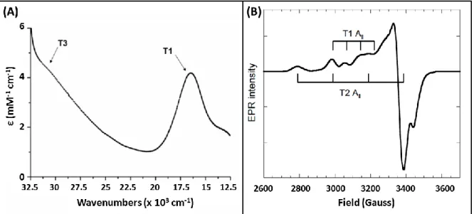
copper is classified according to its optical and magnetic properties. Type I Cu displays an intense absorption band near 600 nm resulting from a charge transfer transition from Cys to Cu (II) and is responsible for the name, blue copper oxidases, given to these enzymes (Fig 1A). It alsoexhibits a small Cu(II) A|| hyperfine coupling constant in EPR (Fig 1B).
Figure 1. UV-visible (A), X-band EPR (B) of purified BOD from Bacillus pumilus highlighting the spectral feature in MCOs. Reprint with permission from ref [101] Copyright 2010 Elsevier.
Type 1 copper accepts electrons from the electron-donating substrates and shuttles them to the O2 reduction site composed of three coppers. The tri-nuclear cluster (TNC)
consists in a Type 2 copper ion active in EPR with a normal Cu(II) A|| hyperfine coupling constant and a pair of Type 3 cupric ions with a characteristic 330 nm absorption shoulder and
14 antiferromagnetically coupled via a bridging hydroxide (Fig 1B). Electrons are relayed from the T1 to the TNC through ~13 Ǻ of Cys-His residues (Fig 2).
Figure 2. The structure of the MCO active site with arrows marking the flow of substrates, electrons (e-), and O2. Reproduced with permission from ref [93]. Copyright 2012 Royal
Society of Chemistry
The exact nature of the electron transfer has been the subject of numerous investigations and is summarized in Figure 3.5,92,94,97,98,102-106
Figure 3. Mechanism of O2 reduction to water by the MCOs. Red arrows indicate the steps
that take place in the catalytic cycle of the MCOs. Black arrows indicate steps that can be experimentally observed but are not part of the catalytic cycle. The dashed arrows at the right indicate the transfer of an electron from the T1 Cu to the T2 Cu to create PI + e-, that occurs in going from PI to NI but is not experimentally observed in the wild type enzyme. Reproduced with permission from ref [93].Copyright 2012 Royal Society of Chemistry
15 Briefly, after oxidation of the substrate at the T1, electrons are shuttled to the TNC where the two two-electron steps of O2 reduction to H2O occurs.93,107,108 The formation of the
peroxide intermediate (PI) results from the first two-electron step with a fast reaction rate ( 106 M-1.s -1). In the second two-electron step, the O-O bond is cleaved with a fast rate constant
leading to the formation of the Native Intermediate (NI). In presence of substrate, NI is reduced to the fully reduced form of the enzyme and is ready for another catalytic cycle. In absence of substrate, NI slowly decays to the resting oxidized (RO) form and only reintegrates the catalytic cycle upon reduction with a substrate.
2.1.1 Laccases
Laccases (Fig 4A) are the most studied MCOs because of their use in different
biotechnological applications; ranging from food applications, pulp bleaching, hair-coloring to organic synthesis.81,109-111 More than 220 species have been identified in insects, fungi or
bacteria.
Figure 4. X-rays structure of different MCOs. A) Native fungus laccase from Trametes
16 efflux Oxidase CueO (PDB: 4NER); D) Tyrosinase from Bacillus megaterium (PDB : 5I38). All Coppers are displayed in blue
Among them, fungal laccases have been the most studied.5,112-114 Laccases are known
to oxidize a variety of polyphenolic compounds concomitant with the reduction of O2. Due to
this latter property, Tarasevich et al. have pioneered the use of laccases for O2 reduction. In
1979, they reported the immobilization of monolayers of laccases on vitreous carbon electrodes, generating O2 reduction currents of 175 A.cm-2 at pH 5.115 The
geometry/coordination of the T1 copper deserves attention since this is the entry point of electrons coming from the electrode or from the redox mediator. It has been shown that its redox potential was modulated by the nature of its coordination. A T1 with a weakly coordinating Met in the axial position exhibits generally a lower redox potential than MCOs where Met has been replaced by non-coordinating Phe or Leu.116 However, many exceptions
exist and the type of coordination cannot explain alone the difference in the observed electrochemical potentials. Other factors such as electrostatic interactions and hydrogen bonds must be taken into account, making therefore difficult to predict the redox potential of MCOs.117 We list here some of the most commonly studied laccases in bioelectrochemistry.
Fungal laccases have been identified in basidiomycetes. Among them we use the abbreviation Th-laccase to call without differentiation the two isoenzymes from Trametes hirsutus, also known as Coriolus hirsutus118, and Tv-laccase to call the laccase from Trametes versicolor,
also known as Coriolus versicolor or Polyporous versicolor. Other laccases are extracted from trees, among which Rv-laccase the laccase from the Japanese lacquer tree Rhus vernicifera.
17 2.1.2 Bilirubin oxidases
BODs (Fig 4B) have been discovered in 1981 by Tanaka and Murao.119 Because of
their ability to oxidize bilirubin, they were classified as BODs and not laccases, even though BODs can also oxidize a variety of phenolic compounds.53 BODs have been primarily used in
the medical field to elaborate bilirubin biosensors.53,58 Only 7 BODs have been
identified/characterized so far, among which BOD from Myrothecium verrucaria (Mv-BOD), the most studied BOD, BOD from Trachyderma tsunodae120 (Tt-BOD), BOD from
Magnaporthae orizae121 (Mo-BOD) and BOD from Bacillus pumilus (Bp-BOD).101 Unlike
Tt-BOD or Mv-Tt-BOD, the two newly identified Mo-Tt-BOD and Bp-Tt-BOD display good thermal stability, a high activity at pH 7 and high temperature, a low sensitivity towards NaCl and no sensitivity to urate. Bilirubin is not a substrate that has been systematically tested with laccases or other MCOs. Therefore, it is not unlikely that MCOs already identified and characterized also display BOD-like activity. The use of Mv-BOD for the electrocatalytic O2
reduction at neutral pH has been reported for the first time in 2001 by Tsujimura et al.122 Ever
since, the number of studies relying on BODs has been flourishing for one main reason: unlike laccases, BODs display a high activity and stability at neutral pH and in presence of chloride. Two points deserve attention. The first concerns the denomination of the enzyme. Reiss et al. recently identified a CotA enzyme from Bacillus pumilus123 which was classified
as a laccase while Durand et al. classified an enzyme sharing 98% identity as a BOD.101
BOD-like activity has also been observed in a CotA from Bacillus subtilis but the enzyme was classified as a laccase.124 Reiss et al. have suggested that the denomination of BOD was
improper since these enzymes could oxidize a variety of substrates. Therefore, they suggested to introduce the term of laccase-like MCOs (LMCOs).125 On the other hand, not all laccases
oxidize bilirubin. Therefore, the denomination of BOD would permit to differentiate between those MCOs that oxidize bilirubin or those that do not. The question of classification remains
18 open. The second point deserving attention, which is linked to the first, is the core structural difference between laccases and BODs. Detailed analysis of amino acid sequences does not permit to differentiate BODs and laccases.126 Combining different analytical tools such as
molecular modeling or X-rays analysis would definitely help, but only two X-rays structures of BODs are available so far, for Mo-BOD127 and Mv-BOD.128,129
2.1.3. Cuprous oxidase and tyrosinase
The two enzymes have been rarely used in O2 biocathodes. Cuprous oxidase, or
copper efflux oxidase (CueO) (Fig 4C) is involved in copper efflux in E.coli.130,131 CueO
possesses the same catalytic site as other MCOs but exhibits a strong activity towards cuprous ion and, unlike other MCOs, no activity towards phenolic compounds. Tyrosinase, or polyphenol oxidase (Fig 4D), only carries a couple of T3 copper atoms and is involved in the ortho-hydroxylation of monophenols and two-electron oxidation of diphenols.95
In the following, we will not consider cerulosplasmin and ascorbate oxidase (EC 1.10.3.3) which have not yet proven their utility in O2 reduction.11 It has been shown that
direct electron transfer (DET) between ceruloplasmin and an electrode surface was feasible under non turnover conditions, but in most cases electrocatalytic reduction of O2 was not
achieved.18,132-135 The only example of O
2 reduction with ceruloplasmin on gold modified
with ferromagnetic particles encapsulated in carbon was reported in 2015 by Matysiak et al.136 However, the current density is too low to envision, so far, application in EBFCs. The
DET of ascorbate oxidase has been reviewed by Shleev18 and also investigated by Atanassov
19 2.2 Basic feature of enzymatic biofuel cells
Detailed thermodynamic and kinetic analyses of enzymatic biofuel cells (EBFCs) have been provided in earlier reviews.19,22,24,61 Therefore, in the following, we only briefly
summarize key points and advantages of EBFCs.
Despite the fact that electrochemical reactions are catalyzed by enzymes at one or both electrodes of the EBFCs, there is no conceptual difference between the latter and conventional fuel cells (CFCs).9 The fuel is oxidized at the anode while the oxidant is reduced at the
cathode, and electrons are exchanged between the two electrodes in an external electrical circuit. The driving force of the reactions is the difference in electrochemical potential between the two electrodes. The transport of charges in the electrolyte solution (or polymer) is ensured by ions. However, unlike CFCs, EBFCs operate at near-neutral pH and ambient temperature. Enzymes also have advantages as electrocatalysts: specificity towards their substrates, renewability, biodegradability, high turnover frequencies, and low intrinsic overvoltages. Moreover, the great diversity of enzymes allows envisioning EBFCs working with diverse fuels and oxidants. In addition, if the bioelectrodes are properly designed, no membrane is needed in EBFCs to separate anodic and cathodic compartments, allowing thereby miniaturization of the devices.
An EBFC is characterized by its current intensity, I, its voltage Ecell, and its power,
defined as the product of these latter:
P [W] = Ecell [V] x I [A] Eq. 1
The electrical current intensity I is the charge flux entering the anode or leaving the cathode. In lots of studies the current density, defined as the ratio of current I by surface area A and denoted j, is preferred. Similarly, the power is often expressed in terms of power density. This makes actually hard to compare the efficiency of different devices because in some (rare)
20 cases the real electroactive surface area of the electrode is considered for the calculation, whereas it is more common to use the projected geometric area.
This point deserves a particular attention. While the normalization of the current is critical for comparing the results of the numerous publications, normalization is difficult. Other difficulties for comparison arise from the fact that experimental conditions (pH, temperature, scan rate, electrode rotation…) differ and in some studies, experimental details (enzymes activities and purities, loading…) are not provided. Natural convection which is often underestimated may also significantly affect current densities.138 Comparisons are even
more difficult when porous materials are used and particularly when detailed characterization of the materials are not provided (BET, thickness, porosity, mass,..). In addition, the different electrochemical techniques used to evaluate the power profile of EBFCs may also be problematic in some cases. For example, using linear sweep voltammetry at a quite fast scan rate (>5 mV.s-1) to evaluate the power profile of EBFCs based on highly porous electrode
materials may induce errors. Since porous materials usually have a high capacitance, it is more than likely that the measured currents are composed by both catalytic and capacitive current, which artificially enhances the biofuel cell performances. In order to evaluate the actual power, the effective catalytic currents have to be determined using chronoamperometry (for individual bioelectrodes) and under continuous discharge (for the biofuel cell setup) at different imposed potentials, or using linear sweep voltammetry at very low scan rates so that the steady-state can be reached. For all the above considerations, it would undoubtedly be useful to develop a protocol for comparison of data, as was already suggested by Minteer and others,139-141 but was not favorably received. The authors of this review believe that such
normalization is much needed, after answering the question of the best way to normalize performances, taking into account the variety of electrode materials, EBFC designs and enzymes used.
21 While in CFCs currents can be measured in A, they are mostly in the range of few tenths of µA to few hundreds of µA (resp. few µA.cm-2 to few mA.cm-2) in EBFCs, or more
generally at enzymatic electrodes. Similarly, power (resp. power densities) are in the range of kW to MW in CFCs whereas they are mostly between few µW and few mW in EBFCs. Some important features of enzymatic electrodes and EBFCs are described in Figure 5.
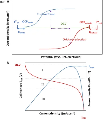
Figure 5. Electrochemical characterization of an EBFC. A: Current/Voltage response of the bioanode (blue curve) and of the biocathode (red curve). The purple arrows indicate the current density and the cell voltage giving the maximum power density. B: Polarization curve (red) and power curve (blue) of the complete EBFC. Adapted from [27]. Copyright 2008 American Chemical Society.
The potential adopted by the electrode at j = 0 is the open circuit potential (OCP). It is close to the onset potential, the starting potential of catalysis. It must be underlined that the
22 definition of “onset potential” is quite fuzzy since it is difficult to define the exact point at which catalysis actually “starts”. The difference between the OCP and the apparent standard redox potential, the overvoltage (), characterizes the deviation to ideality of a catalyst and is a significant measure of its efficiency. Enzymes and MCOs in particular, are potentially powerful catalysts since for most of them electrochemical overvoltages are lower than for conventional catalysts. The difference between the OCP of the biocathode and the bioanode determines the maximal electrochemical driving force or open circuit voltage (OCV, also Ecell
for j = 0) of the EBFC. The OCV of biofuel cells lies below the thermodynamic limit of 1.23 V for H2/O2 EBFCs, but sometimes very close to it,142,143 and below the maximal OCV of
1.18 V for glucose/O2 EBFCs, where glucose is oxidized into gluconolactone at the anode.
EBFC performances can be characterized in terms of OCV, polarization curve and power curve. These two curves show respectively the evolution of the cell voltage and of the power density with the current density (Fig 5B). Particular data are the maximum power density Pmax, and the maximum current density jmax which corresponds very often to the
short-circuit current (i.e. current density for Ecell = 0). As seen in Figure 5B, the polarization curve
can be divided into three regions. In Segment I, the steep decrease of the cell voltage corresponds to kinetic losses, which are related to the slow rate of the electrode reaction due to e.g. slow electron-transfer kinetics. After this first decrease of the cell voltage, the polarization curve continues decreasing more linearly with a smaller slope over a wide range of current density values. This decrease, which can be seen in Segment II, corresponds to the ohmic voltage drop originating from the system’s intrinsic resistance as well as from the resistance to the flow of ions within the electrolyte. Finally, (concentration polarization) losses related to mass transport limitations result in the final decrease of the potential until it reaches zero (Segment III). At that point, the current reaches its maximal value and the system behaves as if the electrodes were in a short circuit. Each of the mentioned potential losses can
23 be described with corresponding overpotentials (Eq. 2). This allows calculating the cell voltage as:
𝐸𝑐𝑒𝑙𝑙 = 𝐸𝑒𝑞− 𝜂𝑎𝑐𝑡− 𝜂𝑑𝑖𝑓𝑓− 𝐼 ∑ 𝑅 𝐸𝑞. 2
where: 𝐸𝑐𝑒𝑙𝑙 and 𝐸𝑒𝑞 are respectively measured and theoretical (thermodynamic) voltages,
𝜂𝑎𝑐𝑡 and 𝜂𝑑𝑖𝑓𝑓 are respectively kinetic (activation) and mass transport based overpotentials, 𝐼
is the current that flows through the cell and ∑𝑅 is the sum of all resistances that are present in the system. The challenge is to minimize all kinetic losses by optimizing each ingredient of the biofuel cell; the electrode material, enzymes, and redox mediators if needed; and by Efficiently integrating them together. It could be done for example by optimizing the cell design and the immobilization of the enzymes.
2.3 Electronic connection of immobilized enzymes
One of the major challenges of using an enzyme as an electrocatalyst is to establish an Efficient electronic connection between the enzyme and the electrode, particularly because of the important size of the protein molecule, and the anisotropy of its electronic properties. A poor electrical connection will induce consequent kinetic losses. Two mechanisms allow electron transfer between an enzyme and an electrode. On one hand, in direct electron transfer (DET), electrons tunnel directly between an enzyme and an electrode. This mechanism relies on the ability of the enzyme to accept electrons not only from its natural substrate but also from artificial electron donors like the electrode. On the other hand, in mediated electron transfer (MET), electrons are shuttled via a redox molecule, called mediator, which exchanges electrons with the enzyme and is reversibly oxidized or reduced at the electrode surface (Fig 6).
24 Figure 6. Two different mechanisms of electron exchange between an enzyme (here a laccase) and an electrode. Left: Direct Electron Transfer (DET) and Right: Mediated Electron Transfer (MET), here with a diffusive mediator.
DET can only occur if the enzyme active site or an electron relay is close enough to the electrode surface. The rate of interfacial electron transfer kET, described by Marcus
semi-classical theory144,145 (Equation 3), depends on the driving force of the reaction (∆G°), the nuclear reorganization energy (λ), and the electronic coupling (HDA) between donor D and
acceptor A. 𝑘𝐸𝑇 =1 ℎ 𝐻𝐷𝐴2 √4𝜋𝜆𝑅𝑇𝑒 −(∆𝐺°+𝜆)2 4𝜆𝑅𝑇 𝐸𝑞. 3
The simplest model to describe the electronic coupling in case of proteins is the « square-barrier model », according to which 𝐻𝐷𝐴2 decreases exponentially with increasing distance between donor and acceptor (rDA):
𝐻𝐷𝐴2 = (𝐻𝐷𝐴0 )2𝑒−𝛽(𝑟𝐷𝐴−𝑟0) 𝐸𝑞. 4
where HDA0 is the electronic coupling at Van-der-Waals distance (r0). The tunnel parameter β
reflects the protein efficiency for electron transfer and depends on the protein structure.146,147
In DET, the catalytic wave is centered on a potential that is only affected by the properties of the enzyme molecule. This is discussed further in section 3.4.5 and 3.4.7. The
25 distribution of orientations allowing DET results in distribution of electronic transfer rates148
reflected by the trailing edge in the catalytic cyclic voltammogram (Fig 7A).
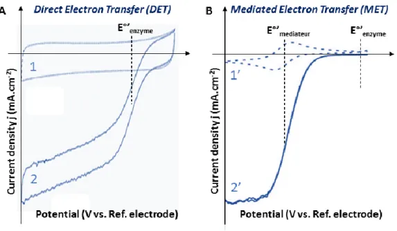
Figure 7. Representative cyclic voltammograms of a MCO in DET (A) and MET (B). Curves 1 and 1’ are recorded in non-catalytic conditions in the absence of O2. Curve 1’ clearly shows
the redox process of the mediator. Curves 2 and 2’ are recorded in catalytic conditions under O2. The dotted vertical bars indicate the apparent standard potentials of the enzyme (E°’enzyme)
and of the mediator (E°’mediator).
Therefore, a performant DET can only be obtained for a monolayer of enzymes properly oriented. Experimentally, it has been verified for redox proteins including MCOs immobilized on SAMs with different alkyl lengths that the efficiency of electron transfer decreases exponentially with increasing numbers of methyl groups.149-151 In proteins,
electrons tunnel through a maximum distance of 14 Å.146
MET is possible if the affinity between the enzyme and the mediator is high enough, and if the difference in their redox potentials induces a driving force for the electron transfer. Both the oxidized and the reduced forms of the mediator must be stable chemically, and of course none of them must inhibit the bioelectrochemical reaction. The mediator can be for example
26 another protein like cytochrome c,152 diffusive species like ABTS or transition metal
complexes, or a metal complex bound to a polymer, like osmium complexes.153 The
corresponding polymers are used in the form of a hydrogel, whose reticulated structure allows permeation of solvent and diffusion of ions and non-charged species. Unlike most hydrogels, osmium based redox polymers are also capable of conducting electrons via self-collision between neighboring oxidized and reduced osmium redox moieties. The “diffusivity” of electrons in the hydrogel depends on the length of the tether that links the osmium complex to the polymer backbone, the characteristic electron-hoping distance between neighboring redox sites, the self-exchange rate constant, and the concentration of redox sites.154 In MET
configuration, the catalytic wave is centered on the mediator potential (Fig 7B).
The two approaches have advantages and drawbacks. DET is reasonably simple and cheap, and allows working with overvoltages close to zero thanks to intrinsic properties of enzymes. However, it requires a unique orientation and only allows the simultaneous connection of a maximum of one monolayer of enzymes. In contrast, MET allows to wire electronically lots of enzymes regardless of their orientation and even in multilayers. The hydrogel especially is a convenient matrix for enzyme immobilization that even protects enzymes from inhibitors. However, electron-hopping in the redox polymer introduces additional steps that can lower the catalytic efficiency of the bioelectrode. A drop of cell voltage is also induced because catalysis is recorded at the potential of the mediator which must be lower than that of the enzyme. Finally, in case of diffusive mediators, a cell membrane is required to avoid cross reactions.
3. Mechanistic studies of MCOs
The catalytic mechanism of MCOs in homogeneous solution has been largely investigated by different spectroscopic techniques, crystallography and density functional
27 theory (DFT) calculations and only partly elucidated.92,93,95 For example, the mechanisms of
MCO inhibition at high pH or high concentrations of halides, or the differences between BODs and laccases are still unclear.
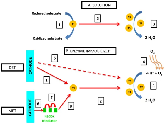
Figure 8. Comparison of different steps for electron transfer for enzymes in solution (A) and immobilized (B) with Direct electron transfer (DET) or Mediated electron transfer (MET). A) Step 1: Substrate oxidation at the T1; Step 2: IET; Step 3: O2 reduction. B) Step 1: Electron
transfer from the electrode to the T1; Step 2: IET; Step 3: O2 reduction; Step 4: O2 diffusion;
Step 5: hypothesized electron transfer from the electrode to the TNC; Step 6: Electron transfer from the electrode to the redox mediator; Step 7: electron transfer within the redox mediator; Step 8 electron transfer from the redox mediator to the T1. Adapted with permission from [155] Copyright 2017 Elsevier
During homogeneous catalysis, oxidation of organic substrates occurs via a ping-pong type mechanism. T1 is the primary center at which electrons from the reducing substrates are accepted,92,93,95,155,156 and O2 is reduced at the TNC (Fig 8). One of the major questions,
4 H++ O 2 2 H2O CA THODE DET ENZYME IMMOBILIZED T1 T3 T3 T2 1 2 5 3 CA THODE Redox Mediator MET 8 6 7 O2 4 3 2 H2O Reduced substrate Oxidized substrate A. SOLUTION T1 T3 T3 T2 2 1 B.
28 however, is whether the mechanism is the same for an enzyme immobilized at the electrode. Intuitively, we may for example expect different rate limiting steps, depending whether the MCOs are connected at the electrode in DET or in MET.
The influences of pH and chloride on the MCOs activity are of particular importance, especially if MCO-based biocathodes are envisioned for BFCs operating in physiological media. In this section, we first present commonly adopted opinion about how pH and halide inhibitors impact on MCO mechanism in homogeneous solutions. Due to the general similarity between mechanism in homogeneous solution and in electrochemistry in MET connection, we simultaneously develop investigations realized in electrochemistry in MET. The reader can find more information about mechanism in homogeneous solution in different specialized reviews.93,157-161 The following part presents a comprehensive view of DET
connected immobilized enzymes. We also consider two less-known inhibitors, hydrogen peroxide and methanol, without differentiating DET and MET, because a priori their effect is similar in both modes.
3.1 Effect of pH on MCOs
The effect of pH on the MCO catalytic mechanism has been the subject of intense research and has only recently been partly elucidated. The first studies were reported in homogenous solution in 1997 by Xu.162 They demonstrated that both high- and low-potential
laccases from Trametes villosa, Rhizoctonia solani and Myceliopthora thermophila were inhibited at neutral pH and above. It was hypothesized that laccases were inhibited upon increasing the pH due to the binding of OH- to the T2 site, therefore interrupting
intramolecular electron transfer between the copper sites.157,158
Solomon et al. investigated in details how pH influences laccases reaction mechanism.93 They particularly tried to decipher which step of the reaction cycle was
29 inhibited at high pHs. Since the rates of formation of the PI and NI states are pH-independent163, these steps cannot be associated to the pH inhibition (Fig. 3). The remaining
possibilities are therefore the formation of the fully reduced form, either from NI or from the resting oxidized form, or an alternative mechanism. More recently, by combining protein film volammetry,164 computational modeling and numerical analysis, Blanford et al.165
investigated the pH dependence of O2 reduction of two high and two low-potential MCOs
immobilized in DET mode. They attributed the pH inhibition to another redox state of the enzymes, unknown so far, called “X state”. This point is detailed further in section 3.4.8. However, since there are no direct spectroscopic or crystallographic features of the “X state”, it cannot be totally excluded that the inhibition effect may come from the NI state. If the formation of NI has been studied extensively, this is not the case of the protons involved during the reduction of NI.105
While the residual activity of laccases is almost nil at neutral pH, irrespective of the redox mediator used, this is not so for BODs.53 Since the specific activity of BODs is
declining with the pH (when ABTS is used as a substrate), one can hypothesize that OH- also
inhibits BODs. Nevertheless, detailed kinetics studies on BODs still have to be performed. Another question remains open: why are BODs less sensitive to pH than laccases?
Different strategies have been explored to prevent laccases inhibition at neutral pH, or to get around it. For example, by switching from a fungal Tv-laccase to the small bacterial laccase from Steptomyces coelicolor, which was reported to be highly active at pH 7, Calabrese-Barton et al. reached 1.5 mA.cm-2 at 40°C and 900 rpm while they only reached
0.2 mA.cm-2 with the fungal one.166 The exact reason for the higher activity of Sc-laccase at
neutral pH still has to be identified. Enzyme engineering and molecular biology are also powerful tools to evolve laccases.167 For example in 2009, Cusano et al.168 succeeded in
30 of a fungal laccase.169 The same authors later used directed molecular evolution to evolve a
basydiomycete laccase.170 After several rounds of evolution, they succeeded in getting a high
redox potential laccase with an optimum activity shifted towards neutral pH and more resistant to chloride. Surprisingly, all mutations were located in the second coordination sphere of the T1. All these engineered enzymes have yet to be tested in electrochemistry. Pita, De Lacey et al.171 proposed a different approach. By locally acidifying the pH at pH 5 near a
modified electrode with Th-laccase, the authors succeeded in keeping the enzyme active while the pH of the bulk solution was 6.5. To create an acidic local pH around the Th-laccase electrode, they used magnetic particles modified with glucose oxidase.
3.2 Halides inhibition
The first detailed studies in homogeneous solution on the effect of halides (Cl-, F-, Br-)
on MCOs activity have been reported in 1996 by Xu using ABTS as a substrate.172 In the
study, the author tested 5 different laccases and Mv-BOD. He concluded that the inhibition order was following the general trend F- > Cl- > Br- and depended on the accessibility of ions
to the TNC. The author also noticed that the magnitude of the inhibition was dependent on the species of laccases, particularly because the latter influences the size of the channel leading to the TNC. All MCOs were inhibited by F-, and Mv-BOD was 1000 times more tolerant to Cl
-compared to laccases. In 2001, Xu reviewed the effect of pH and anions on the inhibition on 5 laccases from different species.157 In 1998, Hirose et al.173 specifically studied the effect of
halides inhibition on bilirubin ditaurate oxidation by Tt-BOD. The inhibition order was SCN-
(thiocyanate)> F- >> Cl- > Br-, and the inhibition was non-competitive.
Mechanistically, the affinity between fluoride and the TNC is a general trait of MCOs and has been the subject of numerous investigations particularly by combining EPR, X-ray crystallography and modeling.158-161 In 2005, Quintanar et al.174 proposed a model in which
31 the binding of F- only occurs in presence of the fully oxidized TNC. It is explained by strong
electrostatic interactions between the negatively charged fluoride and the positively charged fully oxidized TNC. On the contrary, the exact mechanism of chloride inhibition of MCOs in homogeneous solution is not yet elucidated. It is not excluded that Cl- may interact with the
T1 or with the TNC but spectroscopic and crystallographic evidence is still missing.
Because of the envisioned applications of MCOs, the effect of halides on the catalytic reduction of O2 by MCOs immobilized at electrodes has been studied. The current density of
the “wired” Mv-BOD and Tt-BOD electrodes with osmium redox polymer only declined respectively by 6% and 3% in presence of 140 mM NaCl at pH 7.4.120,175 Moreover, even
though fluoride has a very high affinity with the MCOs, the presence of 100 mM F- did not
significantly affect the current density. It can be hypothesized that the electrostatic adduct formed by the enzyme and the redox polymer acts as a shield against Cl- and to some extent F
-. A similar effect has been seen by Calvo et al-. with a self-assembled layer of laccase and osmium bound to poly(allylamine), when the concentration of Cl- in solution was below the
concentration of chloride bound to positively charged groups in the polycationic film.176
When the same redox polymer used to wire BODs was quaternized,177 the effect of fluoride
was much more pronounced, the current declining already by 40% in presence of 20 mM F-.
Quaternization introduces positive charges within the redox polymer and may therefore affect the interaction between enzymes and polymer, exposing the TNC to fluoride. Although BODs already share a relative tolerance to chloride, to prevent even more the inhibition by Cl-, a
different strategy consists in identifying new BODs with increased resistance to it. Durand et al. have for example reported a new BOD from Bacillus pumilus which only loses 20% of its activity towards SGZ oxidation in presence of 500 mM NaCl in a 100 mM citrate–phosphate buffer pH 7.101 Once immobilized within an osmium redox polymer, this new enzyme showed
32 In contrast to BOD electrodes, the effect of Cl- on laccase-modified electrodes is
pronounced. The activity of an electrode modified with osmium polymers and Th-laccase declined by 60% at pH 5 when the chloride concentration was raised from nil to 100 mM.178 It
has been hypothesized that Cl- was a competitive inhibitor towards redox mediators, blocking
their access to the T1 site.179 Even though this hypothesis still has to be clearly proven, strong
evidence has already been reported. For example, Bey et al. designed a new osmium redox polymer with the objective to improve the interaction between the T1 and the osmium, therefore restricting the access of anions to the catalytic site. It resulted in the formation of a chloride-resistant cathode based on Trametes hirsuta.180 The authors also applied the same
strategy to shield CotA from Bacillus subtilis from chloride.181 With the same objective but a
different strategy, Leech et al. used a laccase from Melanocarpus albomyces, which displays an optimal activity near neutral pH,182 co-immobilized with (polyvinylimidazole)10
[Os(2,2’-bipyridine)2 Cl]+/2+. They could reach 3.8 mA cm-2 at 0.2 V in a physiological buffer solution
containing 100 mM NaCl,183 the highest current density reported for laccase at neutral pH,
and later used it in a glucose/O2 BFC.184 The inhibition effect of Cl- on laccase modified
electrodes is also observed in DET, to some extent. For example, when Cerrena maxima laccase was immobilized on graphite particles, the current declined by 30% upon addition of 0.1 M NaCl.185 Salaj-Kosla et al. showed that the activity of nanoporous gold electrodes
modified with a laccase from Trametes hirsuta was strongly dependent on halides in a citrate-phosphate buffer pH 4.186 Addition of fluoride completely inhibited the enzyme because, as
discussed above, F- blocks the electron transfer between the T1 and the TNC. The addition of
200 mM Cl- decreased the current by 50%. In contrast, when the same enzyme was
immobilized on graphite carbon electrodes through phenyl derivatives, De Lacey et al. did not observe any inhibition by Cl-.187 Interestingly, the addition of ABTS as a diffusing redox
33 mediator made the modified electrodes sensitive again to Cl-. This observation tends to
confirm that Cl- may act as a competitive inhibitor towards redox mediators.
3.3 Model of mediated electron transfer
3.3.1 Model
Mathematical models predict and describe the observed steady-state electrochemical currents and concentration profiles of enzymes, substrates and redox mediators. The models consider mass and charge transport, enzymatic reactions and electrode reactions. Modeling coupled reaction/diffusion problems leads to a set of non-linear differential equations that cannot always be solved analytically. Therefore, either analytical solutions are derived under certain hypothesis or simplifications (i.e describing limiting cases), or alternatively numerical full solutions can be simulated. We give below a brief introduction of the models of an MCO cathode based on mediated electron transfer (MET) mechanism. Further details and last achievements can be found in a recent review.90
MET mechanism includes two substrates, O2 and the redox mediator. The mechanism
is described by a non-sequential, or “ping-pong” mechanism, where all steps of enzyme reaction with O2 are included in a global oxygen reduction reaction (ORR) mechanism (Fig
34 Figure 9. Schematic illustration of a MCO-based oxygen-reducing cathode. The processes described in the mathematical model occur throughout the film from x = 0 (electrode surface) to x = l (film thickness). Partition of oxygen between the film and solution is described by the partition coEfficient KP,O2. The motion of charges is described by the apparent diffusion
coEfficient DMed,app of the redox mediator. Oxygen diffusion occurs within the film with a
diffusion coEfficient DO2,app. O2 is reduced by the reduced MCO to H2O, the oxidized MCO is
reduced by the mediator, and the mediator is re-reduced at the electrode surface. Adapted with permission from [188]. Copyright 1995 Elsevier.
The reaction mechanism for MCO can therefore be described by the following equations, derived from a general model of ping-pong mechanism188-191
𝑂2+ 4𝐻++ 𝑀𝐶𝑂
𝑟𝑒𝑑 → 𝑀𝐶𝑂𝑜𝑥+ 2𝐻2𝑂 𝐸𝑞. 5
4𝑀𝑒𝑑𝑟𝑒𝑑+ 𝑀𝐶𝑂𝑜𝑥 → 4𝑀𝑒𝑑𝑜𝑥+ 𝑀𝐶𝑂𝑟𝑒𝑑 𝐸𝑞. 6
and the mediator reduction at the electrode can be expressed as:
𝑀𝑒𝑑𝑜𝑥+ 𝑒− →⃖ 𝑀𝑒𝑑𝑟𝑒𝑑 𝐸𝑞. 7
Typically only the case where both the enzyme and the redox mediator are confined by a membrane or a polymer in the reaction layer at the electrode surface was considered.188-194
35 diffusion coEfficient DMed, app to/from the electrode surface where it is reduced. Alternatively,
in case of a linked redox mediator, charges are propagating by electron-hopping between the neighboring redox sites across the hydrogel layer and the model is formally unchanged. Oxygen is diffusing in the film with an apparent DO2,app. The bulk solution is supposed to be
ideally mixed (i.e. [O2]x=l = constant) and the convection in the catalytic layer can be
neglected. Assuming a one-dimensional diffusion, the following differential equations can then be derived (for 0 < x < l):188,189,193
𝜕[𝑀𝑒𝑑𝑟𝑒𝑑] 𝜕𝑡 = 𝐷𝑀𝑒𝑑,𝑎𝑝𝑝 𝜕2[𝑀𝑒𝑑 𝑟𝑒𝑑] 𝜕𝑥2 − 4𝑣𝐸𝑛𝑧 𝐸𝑞. 8 𝜕[𝑂2] 𝜕𝑡 = 𝐷𝑂2,𝑎𝑝𝑝 𝜕2[𝑂 2] 𝜕𝑥2 − 𝑣𝐸𝑛𝑧 𝐸𝑞. 9
where 𝑣𝐸𝑛𝑧 is the rate of the enzymatic O2 reduction. In some studies, only the
substrate consumption rate was supposed to exhibit a Michaelis-Menten kinetics,188 while in
other cases the catalytic rate constants of the enzymatic reaction were supposed to be independent on both O2 and mediator concentrations.192 The pH-dependency of enzymatic
activity was not taken into account.
It may reasonably be proposed that the model assuming a Michaelis-Menten kinetics both for O2 and the redox mediator, first derived for a stoichiometric coEfficient for electrons,
can be extended to the case of MCOs for which 4 electrons are necessary to reduce 1 molecule of O2. In these conditions, 𝑣𝐸𝑛𝑧 at steady-state is therefore defined as:189,191,193
𝑣𝐸𝑛𝑧 = 𝑘𝑐𝑎𝑡[𝑀𝐶𝑂𝑇𝑜𝑡] 1 +𝐾𝑀,𝑀𝑒𝑑 [𝑀𝑒𝑑 𝑟𝑒𝑑] ⁄ +𝐾𝑀,𝑂2 [𝑂2] ⁄ 𝐸𝑞. 10
kcat is the effective rate constant and 𝐾𝑀,𝑂2 and 𝐾𝑀,𝑀𝑒𝑑 are the effective Michaelis-Menten
36 constants, 𝑘𝑂2, the maximal catalytic rate constant at saturating mediator concentration and
𝑘𝑀𝑒𝑑, the maximal catalytic rate constant at saturating O2 concentration. With the notations
used above, theseconstants are respectively defined as:
𝑘𝑂2 = 𝑘𝑐𝑎𝑡
𝐾𝑀,𝑂2+ [𝑂2] 𝐸𝑞. 11
𝑘𝑀𝑒𝑑 = 𝑘𝑐𝑎𝑡
𝐾𝑀,𝑀𝑒𝑑+ [𝑀𝑒𝑑𝑟𝑒𝑑] 𝐸𝑞. 12
The kinetics of equation 7 defines the boundary conditions of [Mred] at x = 0. It is reasonable
to consider that the electrochemical reaction is reversible and that its kinetics follows a Butler-Volmer law. In most cases, diffusion is considered to be the only mass transport mechanism. In some recent models however, an additional term has been introduced to take into account the mass transport by migration (i.e. the influence of electric field),194or
convection.192
3.3.2 Mathematical modeling
Both analytical and numerical methods have been used to derive the equations describing the behavior of an enzymatic electrode188-193,195,196 or more rarely of complete
EBFCs.90,194
3.3.2.1 Analytical solutions
In a first fundamental study Bartlett et al.188 built a case diagram based on complete
analytical solutions derived for a set of limiting cases. In their study, they only considered a Michaelis-Menten kinetics for the substrate conversion (i.e. O2 reduction in our case). Figure
10 shows the 2D case diagram corresponding to the further assumption that diffusion/reaction of redox mediators are well balanced with diffusion/reaction of substrate in the reaction film
37 (in our case it would correspond to 𝐷𝑂2,𝑎𝑝𝑝
𝐾𝑀,𝑂2
𝑘𝑂2 = 𝐷𝑀𝑒𝑑,𝑎𝑝𝑝 𝐾𝑀,𝑀𝑒𝑑
𝑘𝑀𝑒𝑑 ), while substrate
concentration is below the saturation condition in the film (KP,O2[O2] << KM,O2).
Figure 10. Two-dimensional case diagram showing the five limiting cases predicted analytically. The concentration profiles surrounding the case diagram are from simulations at the points marked () on the case diagram: case I, = 0.1, = 0.01; case II, = 10, = 0.001; case III, = 10, = 1; case IV, = 10, = 1000; case V, = 0.l, = 100. The continuous lines indicate dimensionless mediator concentration profiles ([Medred]/[MedTot], assuming that
the mediator is confined in the film); and the dotted lines the dimensionless substrate concentration profiles ([O2]/KP,O2[O2]). Horizontal scale is from x = 0 (electrode) to x = 1
(bulk solution). Vertical scale is dimensionless concentration. Note the compressed vertical scale for profiles I and V. Reprinted with permission from [188]. Copyright 1995 Elsevier.
The two dimensionless coordinates of the resulting case diagram are , which describes the relative thicknesses of the film and diffusion layer; and , the relative concentrations of enzyme in its reduced or oxidized forms. In the first case (I), the limiting step is the enzyme-mediator reaction (i.e. mass and charge transport of substrates and redox