Design of Housing for Stove Use Monitors (SUMs) to Measure Adoption
by
Erica Waller
Submitted to the
Department of Mechanical Engineering
in Partial Fulfillment of the Requirements for the Degree of
Bachelor of Science in Mechanical Engineering
at the
Massachusetts Institute of Technology
June 2017
MASSACHUSETTS INSTITUTE OF TECHNOLOGYJUL 25 Z017
LIBRARIES
ARCHIVES
2017 Massachusetts Institute of Technology. All rights reserved.
Signature of Author:
Certified by: _
Signature redacted
Department of Mechanical Engineering
May 12, 2017
Signature redacted
9
A'Z01-X
7Daniel
FreyDesign of Housing for Stove Use Monitors (SUMs) to Measure Adoption
by
Erica Waller
Submitted to the Department of Mechanical Engineering on May 12, 2017 in Partial Fulfillment of the
Requirements for the Degree of
Bachelor of Science in Mechanical Engineering
ABSTRACT
Billions of people around the globe rely on solid fuels such as wood or charcoal to heat their homes and cook their meals which negatively impacts health as well as the environment. Improved cook stoves negate these problems but are often not used over time. Stove use monitors (SUMs) are attached to improved cook stoves to track adoption rates. Three basic designs were generated of a housing for the SUM. They were analyzed by considering material choices, manufacturing options, and customer needs. Thermal images were taken of an improved cook stove in use to measure temperatures at key locations around the stove. It was found that the sides and handles of the stove attain a maximum temperature of above 150 "C (300 *F), and the feet and base of the stove below that. It was determined the best course of action is to design a housing for the base or feet of the stoves and use resin casting and later injection molding as production needs increase.
Thesis Supervisor: Daniel Frey
Acknowledgements
The author would like to thank Prithvi Sundar for allowing me to work with him on this project, Dan Sweeny and Amit Gahndi for getting me started with the project and helping me set things on fire, Matt McCambridge for connecting me with the project in the first place, Dan Frey for being my supervisor and editing this document, and Jack Whipple for supplying sour gummies and shop space.
Table of Contents Abstract 3 Acknowledgements 5 Table of Contents 7 List of Figures 8 List of Tables 9 1. Background 11
1.1 Design Specifications and Challenges 11
2. Preliminary Designs 13
3. Thermal Analysis 14
3.1 Experimental Setup and Results 14
4. Manufacturing Considerations 15
5. Summary and Conclusion 16
6. Appendices 17
Appendix A: Design Sketches 17
Appendix B: Basic CAD Renderings 20
Appendix C: Thermal Imaging Pictures 23
List of Figures
Figure 1-1: Figure 2-1: Figure 2-2: Figure 3-1: Figure 3-2a: Figure 3-2b:SUM internal components
Greenway Smart Stove Makaa Cook Stove
Experimental setup with a Makaa stove Thermal image of max handle and side temps Thermal image of max base and foot temps
11
13 14 14 15 15List of Tables
1. Background
Billions of people across the globe use open fires and simple cook stoves to cook their meals and heat their homes (1), the effects of which produce consequences for the individuals and for the planet. Household air pollution leads to health problems such as stroke, chronic obstructive pulmonary disease (COPD), pneumonia, and other respiratory and cardiovascular conditions. The burning of solid fuels like wood or coal by households in the developing world contributes to around 21% of global black carbon emissions (2). Deforestation, emissions, and particulates resulting from residential use of solid fuels adds a non-negligible contribution to climate change.
A method to combat the negative consequences of solid fuels while remaining economically
viable in the developing world is to improve cook stoves. More efficient stoves require less fuel, reducing emissions and impact on the environment.
There are several models of improved cook stoves on the market utilizing different fuel sources. Some use wood but include methods to reduce smoke and increase heating efficiency while others use charcoal. Charcoal burns hotter and cleaner than wood, producing no smoke as volatile gasses are burned off as they are released (3). However, charcoal production still impacts the environment greatly. Both types of fuel can be used under different circumstances to reduce the impact of indoor air pollution on the health and wellbeing of families in the developing world.
High-performance improved cook stoves and other improved cooking technologies are often financially out of reach of many households. Government organizations and non-profits typically employ donations of stoves to distribute the technology to households in need, but adoption rates tend to be low (4). Low adoption of improved cook stoves mitigates their benefits. The purpose of this project is to design a housing for a stove use monitor (SUM) that provides manufacturers and designers with data regarding the adoption of their product. This data can be used to
investigate causes for low adoption rates, allowing producers to address these issues and increase adoption among their customers in the long term.
1.1 Design Specifications and Challenges
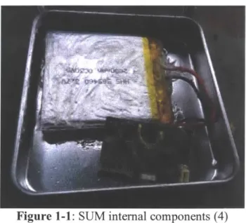
The SUM consists of a lithium ion battery, a thermal sensor, an SD card reader, and the supporting electronics (see figure 1-1). The thermal sensor must be able to register changes in temperature in order to track use of the stove, but the LiPo battery degrades quickly under high heat. This presents one of the major challenges in the housing design: how to thermally isolate the battery while maintaining a small housing footprint and allowing the thermal sensor to measure temperature changes of the stove.
- - - -- -- --- - - -~--~--- -I
Figure 1-1: SUM internal components (4)
The LiPo battery is the largest component in the housing, driving its shape and size. A table of
functional requirements is included below (5). Other customer needs to be considered are
aesthetics of the final design, usability of the stove with the SUM attached, ability to clean the
SUM as needed, and accessibility of the battery and SD card for data collection and
maintenance.
Table 1-1: Functional requirements of the SUM housing
Other challenges considered in this project were material selection, battery type, and
scale of production, specifically with regards to heat resistance, resistance to the cooking
environment, and cost of production at medium scale. Initial prototypes were made of small
metal boxes, but future iterations must blend seamlessly with the stove and not interfere with
normal use. Different manufacturing processes were considered such that the design could be
changed slightly to suit different techniques as the project scales up. Ideally production would
begin with lOs of units, scaling eventually to 1 000s of units or more over time. Of particular
interest was utilizing 3D printing for prototyping, urethane casting, and eventually small-batch
injection molding as production needs increase.
Function Specification
Must
withstand
Heat resistant
100-250 C
UL 94 V-1
Flame-Proof
classification
Able to
withstand
Shock resistant
falls of 3ft
IP54
2. Preliminary Designs
Initial design ideas focused on the mounting interface for a Greenway Smart Stove, an
improved cook stove that uses wood for fuel (6) (see figure 2-1). The handle in particular was
chosen as a potential location for housing the SUM in a way that would not interfere with
customer use of the stove and would not change the overall aesthetic of the design.
Figure 2-1: Greenway Smart Stove, from Amazon.com
The scope of the project was later increased to consider a SUM housing that could
integrate with many types of improved cook stoves, such as the Makaa Cook Stove, which are
often made locally to increase the economic impact of the cook stoves in the communities where
they will be used. This adds a challenge because each stove is different, even when the design is
the same. Manufacturing tolerances in a local mechanic's shop in Uganda differ greatly from
those in a factory in the US or China. In this case, preliminary designs focused more on
flexibility of attachment to different stove models. Three main design and mounting ideas were
considered, design 1 that attaches as a handle, design 2 that attaches as a foot, and design 3 that
can be attached under the stove or on its side, as needed. See Appendix A for detailed sketches
and Appendix B for basic CAD models of the main design ideas.
3. Thermal Analysis
In order to better understand the temperature changes seen by various locations on a cook
stove during normal use, a burn test was conducted on a Makaa Cook Stove. A Seek Thermal
thermal imaging camera was used along with an Android smartphone to take pictures of specific
locations on the stove approximately every
5
minutes until max temperature was reached for
each location and the fire had died down to embers.
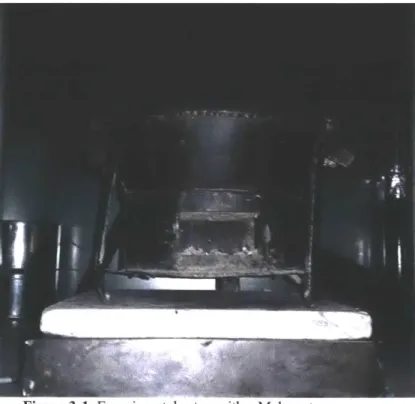
3.1 Experimental Setup and Results
A Makaa cook stove was set under a fume hood in the IDC burn lab. The clay liner of the
stove was filled with natural wood lump charcoal and a fire starting cube of wax and wood
shavings was placed on top. This cube was lit with a lighter and the Seek Thermal camera was
inserted into the smartphone. Once the fire began burning steadily, a pot of water was placed on
top of the stove to simulate cooking. The burn lasted about two hours, and thermal images were
taken focusing on the sides of the stove, the handles, the base of the stove, and the feet. The
experimental setup can be seen in figure 3-1 and thermal images can be found in Appendix C.
Figure 3-1: Experimental setup with a Makaa stove
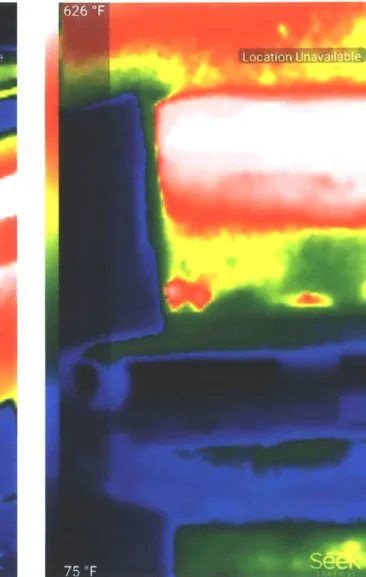
The resulting data showed the approximate maximum temperatures reached for each part
of the stove. The sides of the stove saw the highest temperatures of around 320 *C (600 *F),
followed by the handles at 150
*C
(300
*F),
the base at 135
*C
(275
*F),
and the feet at 60
*C
(140
*F).
As expected, the temperature dropped with the distance from the fire, but the handles
got much hotter than expected given that they should be able to be touched. This should be
employs plastic handles, but many use metal handles as the Makaa stove does. The LiPo
batteries currently being used for the SUM have a discharge temperature range of -20 'C
-
60 'C
(-4 OF
-
140 OF) (7). The temperature of the battery should not exceed this temperature range or
the life of the battery will be negatively impacted, so housing designs must also protect the
battery thermally.
Figure 3-2a: Thermal image of max handle and side temps. Figure 3-2b: Thermal image of max base and foot temps
4. Manufacturing Considerations
Based on the current scale of the project and the thermal imaging data, manufacturing
options were explored including method of manufacture and choice of materials for small and
stage, material choices widen further to include thermoplastics like nylon or ABS, which are low cost and easily machined. There are also high temperature plastics like PEEK which have higher costs but offer significantly increased thermal performance (9).
Also at medium scale production, sheet metal parts become feasible. Simple boxes can be easily stamped for fairly low cost given higher volumes of production. Metal offers excellent thermal capacity though increased conductivity could prove troublesome with regards to the battery. In this case, insulation materials like fiberglass become vital to maintain battery life. At
low volumes of production, metal parts are too costly to produce as they must be machined or individually assembled, as in welding steel boxes. As a result, casting seems to be the best choice for low volume followed by either stamping or low volume injection molding as production scales up.
5.
Summary and Conclusions
After consideration of production needs, cost limitations, thermal data, and customer needs, it was determined that design 2 was most promising. This design provides minimal disruption to the user unlike a mount to the side of the stove. It also allows the handles to be any size or material. Also, the temperature of the base and feet of the stove remained much lower than the handles or sides opening up material and manufacturing options that would be otherwise unusable due to thermal constraints. The recommendation is to iterate design 2 to be easily molded and to provide the appropriate insulation for the battery. This design will likely work best if the thermal sensor is located on top of the battery so the battery is as far removed from the heat source as possible. The temperature at the base remains low enough for cheaper plastics like ABS to be used but high enough for the sensor to detect a noticeable change when the stove is in use.
For increasing production, rapid prototyping is recommended in the small scale stage and low volume injection molding for medium scale and beyond. The small scale production is best done using resin casting for its low cost and ease of use. Injection molding makes the most sense in medium production because shifting from casting to sheet metal stamping would require a rather dramatic shift in design and previous prototyping work would likely be wasted since the challenges of stamping differ from molding.
Future work should focus on optimizing the basic design for mold production and thermal analysis to verify that the battery is properly insulated given the materials and wall thicknesses chosen. Ideally the final design would be unnoticeable to the user entirely so as to increase the number of users willing to allow data collection via the SUM about their stove use habits.
6. Appendices
Appendix B: Basic CAD Renderings
Design 1
Concerns here are the thickness of the handle required for the battery to fit. The handle may be
too large for comfortable use.
-- -. -. - U
o
-0s"M.
t
.T
1.,
"-." :. ,I
'f : :: "01
' -:| ' ..---|.
1
els".
--. r--r
Design 2
Design could be shrunk slightly to be just big enough for the battery, or left as is to allow
insulation to be placed around it.
Design 3
Option B allows the battery and sensor to be configured in several different ways but may
require additional material to keep the components from moving.
Appendix C: Thermal Imaging Pictures
7. References
1. World Health Organization. Household Air Pollution and Health. World Health
Organization. [Online] February 2016. http://www.who.int/mediacentre/factsheets/fs292/en/.
2. United Nations Foundations. Cooking and Climate Change. Global Alliancefor Clean
Cookstoves. [Online] 2013.
http://carbonfinanceforcookstoves.org/about-cookstoves/cooking-and-climate-change/.
5. International Electrotechnical Commission. IEC 60529: degrees of protection provided by
enclosures (IP code). 1989. See appendix.
6. Greenway. Greenway Smart Stove. Greenway Appliances. [Online] 2017.
https://www.greenwayappliances.com/greenway-smart-stove.
7. Shenzhen Honghaosheng Electronics Co., Ltd. 1 OOOmAH-2000mAH. Shenzhen
Honghaosheng Electronics Co., Ltd. [Online] 2016. http://www.sz-battery.com/productshow-67-116-1.html.
8. RTP Co. Comparative Properties of High Temperature Resins. RTP Co. [Online] 2016.
https://www.rtpcompany.com/products/high-temperature/comparative-properties-of-high-temperature-resins/.
9. Proto Labs. Material Comparison Guide. Proto Labs. [Online] 2017.
https://www.protolabs.com/materials/comparison-guide/.
10. Buongiorno, Prof. Jacopo. Personal Collection of Prof. Jacopo Buongiorno. Final Exam