Design of an Endoscope Lens Shielding Device for use in Laparoscopic Procedures
by
Emily Faith Houston and
Jarred Lee Schantz and
ARCHIVES
MASSACHUSETTS INSTME OF TECHNOLOGYJUN 3
0
2010
L9PARIES
Evan Michael Lampe
Submitted to the Department of Mechanical Engineering in Partial Fulfillment of the Requirements for the Degree of
Bachelor of Science in Mechanical Engineering at the
Massachusetts Institute of Technology June 2010
C 2010 Emily Faith Houston, Evan Michael Lampe, and Jarred Lee Schantz. All rights reserved.
The authors hereby grants to MIT permission to reproduce and to
distribute publicly paper and electronic copies of this thesis document in whole or in part in any medium now known or hereafter created.
Signatures of Author.
Department of Mechanical Engineering May 13, 2010
Certified by ... C d b er ifi .. .. ... ... ... ... .. ... ...... Alexander H. Slocum
Neil and Jane Pqnnnaa 'ofessor of Mechanical Engineering Thesis Supervisor
Accepted by ... . d . . ...
John H. Lienhard V ofessor of Mechanical Engineering Chairman, Undergraduate Thesis Committee
Design of an Endoscope Lens Shielding Device for use in Laparoscopic Procedures
by
Emily Faith Houston and
Jarred Lee Schantz and
Evan Michael Lampe
Submitted to the Department of Mechanical Engineering on May 13, 2010 in Partial Fulfillment of the Requirements for the Degree of Bachelors of Science in
Mechanical Engineering
ABSTRACT
Laparoscopic surgical tools and techniques have revolutionized many gynecological and abdominal procedures, leading to dramatic reductions in recovery time and scarring for the patient. While techniques and instruments for performing laparoscopic surgery have improved over the years, loss of vision through the endoscopic lens caused by fog, liquid, and solid debris common to laparoscopic procedures remains a significant problem. In this paper, the prototype of a shielding mechanism that maintains visibility through the laparoscope by removing debris from the distal end of the lens is presented. This device provides an inexpensive, disposable, and convenient alternative to the current practice of removing, cleaning, and re-inserting the laparoscope during surgical procedures. This device is shown in multiple trials to repeatedly remove debris from the distal tip of the lens, thereby restoring vision for the surgeon without requiring removal or reinsertion of the endoscope.
Thesis Supervisor: Alexander H. Slocum
Design of an Endoscope Lens Shielding Device for use in Laparoscopic Procedures
by
Evan Michael Lampe and
Jarred Lee Schantz and
Emily Faith Houston
Submitted to the Department of Mechanical Engineering in Partial Fulfillment of the Requirements for the Degree of
Bachelor of Science in Mechanical Engineering at the
Massachusetts Institute of Technology June 2010
C 2010 Emily Faith Houston, Evan Michael Lampe, and Jarred Lee Schantz. All rights reserved.
The authors hereby grants to MIT permission to reproduce and to
distribute publicly paper and electronic copies of this thesis document in whole or in part in any medium now known or hereafter created.
Signatures of Autho1
Department of Mechanical Engineering May 13, 2010 Certified by ...
Accepted by ...
... ... I ....---.-Alexander H. Slocum Neikan Pappalardn Professor of Mechanical Engineering
. Thesis Supervisor
... .5 . ... ... ...
John H. Lienhard V
-:ofessor of Mechanical Engineering
Design of an Endoscope Lens Shielding Device for use in Laparoscopic Procedures
by
Evan Michael Lampe and
Jarred Lee Schantz and
Emily Faith Houston
Submitted to the Department of Mechanical Engineering on May 13, 2010 in Partial Fulfillment of the Requirements for the Degree of Bachelors of Science in
Mechanical Engineering
ABSTRACT
Laparoscopic surgical tools and techniques have revolutionized many gynecological and abdominal procedures, leading to dramatic reductions in recovery time and scarring for the patient. While techniques and instruments for performing laparoscopic surgery have improved over the years, loss of vision through the endoscopic lens caused by fog, liquid, and solid debris common to laparoscopic procedures remains a significant problem. In this paper, the prototype of a shielding mechanism that maintains visibility through the laparoscope by removing debris from the distal end of the lens is presented. This device provides an inexpensive, disposable, and convenient alternative to the current practice of removing, cleaning, and re-inserting the laparoscope during surgical procedures. This device is shown in multiple trials to repeatedly remove debris from the distal tip of the lens, thereby restoring vision for the surgeon without requiring removal or reinsertion of the endoscope.
Thesis Supervisor: Alexander H. Slocum
Design of an Endoscope Lens Shielding Device for use in Laparoscopic Procedures
by
Jarred Lee Schantz and
Evan Michael Lampe and
Emily Faith Houston
Submitted to the Department of Mechanical Engineering in Partial Fulfillment of the Requirements for the Degree of
Bachelor of Science in Mechanical Engineering at the
Massachusetts Institute of Technology June 2010
© 2010 Emily Faith Houston, Evan Michael Lampe, and Jarred Lee Schantz. All rights reserved.
The authors hereby grants to MIT permission to reproduce and to
distribute publicly paper and electronic copies of this thesis document in whole or in part in any medium now known or hereafter created.
Signatures of Authors ...
/'Department of Mechanical Engineering May 13, 2010 C ertified b y ... ... ...
Alexander H. Slocum Neil and Jane Pappalardo Professor of Mechanical Engineering Thesis Supervisor Accepted by ...
John H. Lienhard V s Professor of Mechanical Engineering Chairman, Undergraduate Thesis Committee
Design of an Endoscope Lens Shielding Device for use in Laparoscopic Procedures
by
Jarred Lee Schantz and
Evan Michael Lampe and
Emily Faith Houston
Submitted to the Department of Mechanical Engineering on May 13, 2010 in Partial Fulfillment of the Requirements for the Degree of Bachelors of Science in
Mechanical Engineering
ABSTRACT
Laparoscopic surgical tools and techniques have revolutionized many gynecological and abdominal procedures, leading to dramatic reductions in recovery time and scarring for the patient. While techniques and instruments for performing laparoscopic surgery have improved over the years, loss of vision through the endoscopic lens caused by fog, liquid, and solid debris common to laparoscopic procedures remains a significant problem. In this paper, the prototype of a shielding mechanism that maintains visibility through the laparoscope by removing debris from the distal end of the lens is presented. This device provides an inexpensive, disposable, and convenient alternative to the current practice of removing, cleaning, and re-inserting the laparoscope during surgical procedures. This device is shown in multiple trials to repeatedly remove debris from the distal tip of the lens, thereby restoring vision for the surgeon without requiring removal or reinsertion of the endoscope.
Thesis Supervisor: Alexander H. Slocum
Design of an Endoscope Lens Shielding Device for use in Laparoscopic Procedures
by
Emily Faith Houston
Submitted to the Department of Mechanical Engineering on May 13, 2010 in Partial Fulfillment of the Requirements for the Degree of Bachelors of Science in
Mechanical Engineering Statement of Personal Contribution
As a member of the three-person team responsible for the design and development of the product described in the following document, I worked with my teammates on this lens cleaning system in the course 2.752: Developing Mechanical Products in spring 2010. I continued this project from the fall 2009 course 2.750: Precision Machine Design. As the single returning team
member from the group that designed the proof-of-concept for this system, I was responsible for recruiting new team members who could help take the product from a conceptual stage into a beta prototype that could be licensed to manufacturers.
Once the team was gathered and throughout the semester, I researched and presented clinical and background information on laparoscopic procedures to provide relevance and market data for use in a business plan. We presented five times throughout the semester to fellow students, faculty, and industry professionals, and I contributed to the construction and presentation of the
information about our product and the market. I scheduled and attended weekly design meetings, organizing an agenda to work efficiently with our advisors during the one-hour meetings. In March 2010 I went to the Carl Shapiro Simulation and Skills Center at Beth Israel Deaconess Medical Center, where I measured the dimensions and tolerances of the laparoscopes with which
our product should work. I also dimensioned the trocars through which our device had to fit during surgery. At the end of April 2010, I traveled with the team to Providence, Rhode Island, where we conducted porcine testing of our device at Rhode Island Hospital. I aided in the editing
and compilation of this paper at the end of the semester.
Throughout the design process I have learned and taken part in the patent process, assembling and filing a provisional patent for the work done in 2.75 in March 2010. In May 2010 I filed a patent memo for the work done in 2.752 with the MIT Technology Licensing Office. Through
these experiences, I gained a good amount of knowledge about timing, costs, and content of United States patents. In mid-April 2010 I attended the ASME Design of Medical Devices conference in Minneapolis, Minnesota, during which I presented a poster describing the clinical need, design process, and potential market for our product to industry and medical professionals. At this conference I gained insight to the medical device market and design research in general. Thesis Supervisor: Alexander H. Slocum
Design of an Endoscope Lens Shielding Device for use in Laparoscopic Procedures
by
Evan Michael Lampe
Submitted to the Department of Mechanical Engineering on May 13, 2010 in Partial Fulfillment of the Requirements for the Degree of Bachelors of Science in
Mechanical Engineering
Statement of Personal Contribution
As a member of the three-person Laparoscopic Lens Cleaning Team, through the class 2.752 Development of Mechanical Products, I contributed fully to the work done in the spring of 2010 which is presented in the following document. Attending every group meeting, I played an integral role along side the other two group members in bringing the current design and prototype to life. In particular, I focused significant attention on the designs of the case, linear actuator, and ratchet components of our product to improve manufacturability and simplify assembly. I developed free-body diagrams to model the forces in the device and analyzed the input forces and tape tension forces. I also created solid models and drawings for the case, linear actuator, and ratchet components.
Additionally, I helped create prototypes for bench-level testing, and I 3D printed the plastic parts of the device for product testing throughout the development of the design. In April 2010 I traveled with the team to Rhode Island Hospital and conducted porcine testing in their pig laboratory using our device. I also participated fully in developing all presentations given throughout the semester. Developing the prototype components, analyzing the free-body diagrams, and looking at design for manufacture and assembly among other things, I produced slides which were shown to potential investors and colleagues. For the final document, I worked closely with the team to produce a detailed account of our new device design. Lastly, in addition to those listed above, more
intangible contributions were made to make the design possible. Thesis Supervisor: Alexander H. Slocum
Design of an Endoscope Lens Shielding Device for use in Laparoscopic Procedures
by
Jarred Lee Schantz
Submitted to the Department of Mechanical Engineering on May 13, 2010 in Partial Fulfillment of the Requirements for the Degree of Bachelors of Science in
Mechanical Engineering
Statement of Personal Contribution
As a member of the three-person Laparoscopic Lens Cleaning Team, through the class
2.752 Development of Mechanical Products, I contributed fully to the work done in the
spring of 2010 which is presented in the following document. Attending every group meeting, I played an integral role along side the other two group members in bringing the
current design and prototype to life. In particular, I focused significant attention on the design of the tip guide and sheath components of our product. I analyzed and determined the correct dimensions and tolerances for each part that must enter the trocar, and created
solid models and drawings for each part. Additionally, I helped create prototypes for bench-level testing throughout the development of the design.
In April 2010 I traveled with the team to Rhode Island Hospital and conducted porcine testing in their pig laboratory using our device. I also participated fully in developing all presentations given throughout the semester. Analyzing current and future market structure, determining cost estimations for our device, and looking at design for
manufacture and assembly among other things, I produced slides which were shown to potential investors and colleagues. For the final document, I worked closely with the team to produce a detailed account of our new device design. Lastly, in addition to those listed above, more intangible contributions were made to make the design possible. Thesis Supervisor: Alexander H. Slocum
Table of Contents
Chapter 1 Introduction ... 6
Chapter 2 Background ... 6
2 .1 P rior A rt ... 6
2.2 Functional Requirements ... 7
2.3 First Design Iteration ... 7
C hapter 3 D esign ... 8
3.1 Bench-Level Testing ... 8
3.2 Tape Guidance and Sealing ... 10
3.3 Dimensioning and Tolerancing ... 11
3.4 A ctuation ... 12
3.5 Design Considerations ... 13
3.6 Analytical Model ... 14
3.7 Prototyping ... 17
Chapter 4 Testing ... 17
4.1 Actuation and Visibility ... 17
4.2 Sterilization ... 19
Chapter 5 Business Considerations ... 20
5 .1 C o st ... 2 0 5.2 C om petitors ... 2 1 Chapter 6 Conclusion and Future Work ... 21
Acknowledgements ... 22
R eferences ... 23
List of Figures
Figure 1 Isometric view of ratchet mechanism compartment ... 8
Figure 2 Tape bending over curved surface ... 9
Figure 3 Visibility through tape ... 9
Figure 4 Dual-ratchet mockup ... 10
Figure 5 Curved, transparent tip guide ... 11
Figure 6 Completed assembly with labeled components ... 13
Figure 7 Case design features ... 14
Figure 8 Free-body diagram of clean ratchet ... 15
Figure 9 Free-body diagram of dirty ratchet ... 16
Figure 10 Force input to device ... 16
Figure 11 3D printed prototype ... 17
Figure 12 Assembly of device with endoscope inserted ... 18
Figure 13 Visibility testing with natural light ... 18
Figure 14 Visibility testing with scope light ... 19
Figure 15 Model of scope placement ... 25
Figure 16 Vision test ... 28
Figure 17 Tape guide mechanism ... 30
Figure 18 Ratchet mechanism illustration ... 31
Figure 19 Endoscope and shielding device before assembly ... 34
Figure 20 Endoscope and shielding device during insertion ... 34
List of Tables
Table 1 Estimated cost breakdown of device ... 20
Table 2 Functional requirements and design parameters ... 24
Table 3 Range of motion ... 26
Table 4 Pugh chart evaluation of selected concepts ... 27
Table 5 Estimated cost breakdown of the design 1 device ... 37
List of Appendices Appendix A Functional Requirements ... 24
Appendix B Range of Motion ... 25
Appendix C Concept Selection ... 27
Appendix D Design 1 ... 30
Appendix E Dimensions and Force Values ... 33
Appendix F Design 1 Testing ... 34
1 Introduction
Laparoscopic surgery provides a minimally invasive alternative to often-risky open procedures. Increasingly popular in recent years, laparoscopic surgery is currently used in many medical specialties, including urology, gynecology, and gastroenterology [1, 2]. Its benefits include decreased operative trauma, decreased wound complications, shortened hospital stay, and shorter-term disability after surgery. Laparoscopic surgery is facilitated by a laparoscope, which provides a view of the anatomical structures in the abdomen and pelvis during the procedure [3].
In many laparoscopic procedures, a 5-10mm diameter cannula sleeve is inserted into the incision to serve as an entry port for the endoscope and allow the endoscope to move with respect to the abdominal wall. A typical laparoscope consists of a lens and light source on the distal end, an elongated lens shaft which passes through the cannula, and a camera or viewfinder on the proximal end outside the body. One of the limitations of conventional laparoscopes is that during surgical procedures, the distal lens frequently contacts and/or is obscured by fog, blood, saline, and other particulate. This reduces or obscures the surgeon's view of the worksite and often requires an interruption of the procedure to clear the debris. Currently, surgeons often attempt to restore vision through the endoscopic lens by wiping it on nearby organs, or removing it from the body to wipe it by hand. In a procedure where the surgeon's vision of the working area is entirely dependent on the scope image, obfuscation of the lens can waste precious time and reduce visibility at times when it is needed most; such as those in which bleeding or other fluid loss occurs [4].
To address the problem of lens obfuscation and its attendant procedural interruption, the current system is presented and described. This system uses a transparent film to shield the endoscopic lens from debris and thereby avoid the loss of vision common to current practice. This design consists of a single, disposable lens shielding tool that when used in conjunction with existing laparoscopes increases visibility and decrease the procedural interruptions during minimally invasive surgery.
2 Background
2.1 Prior ArtWhile many solutions for cleaning the laparoscopic lens have been proposed, none have been effectively implemented nor widely adopted. Ranging from lens flushing devices to mechanical wipers to continuously-flowing air jets, these solutions seek to clean the lens once it has been fogged or soiled by debris [5,6]. Shielding, or the use of a cover over the lens to prevent the lens from actually getting dirty, provides a mechanical, repeatable solution to the problem of lens dirtying in laparoscopic surgery.
U.S. Patent No. 6,193,731 discloses a method for inserting a thin sheet or film of surgical material into the abdomen via a cannula. This patent describes inserting and leaving behind this thin sheet or film of surgical material, and is thus not a lens cleaning method.
The disadvantage of leaving a film behind is that it increases risk to the patient during recovery. Another use of shielding is disclosed in U.S. Patent No. 4,976,254 and No. 5,123,402 though these patents disclose a shield to prevent the surgeon or close observers from experiencing splash back of bodily fluids outside of the body. U.S. Patent No. 6,607,606 discloses a method and apparatus for shielding a lens, as in a camera, from dry particle contaminants through a rotating cleaning mechanism. The invention described in this paper serves as an add-on to current laparoscopes. It shields the lens from both solid and liquid debris and prevents contaminants from obscuring the image seen through the camera. This device is self-contained, leaving no film or residue behind in the body. 2.2 Functional Requirements
In order for this device to provide a useful replacement for the current methods and devices available, it needs to meet several important criteria. Because this is a medical device, it is absolutely imperative that it pose no increased risk to the patient. The device must also provide adequate visibility through the scope and improve visibility in the case of partial or full lens obfuscation for at least 60 cycles per procedure. It is also absolutely necessary that the device meets FDA standards and conforms to industry standards. This requires that the device integrate with 5mm laparoscopes and 5mm cannulas as to ensure no increase in incision size. Other non-critical, though beneficial requirements include keeping device actuation time under 5 seconds and its cost under $100. An exhaustive list of all functional requirements is outlined in Appendix A, in addition to metrics for evaluating the success of this device in fulfilling the functional requirements.
The concept of a device to maintain visibility through a laparoscope via a transparent film was first developed by a team of mechanical engineers at MIT. The issue of view
obstruction during laparoscopic surgeries was presented to the 2.75 Precision Machine Design course in fall 2009. Based on the functional requirements outlined above, the team developed the first iteration of a device to safely and repeatedly restore vision during a laparoscopic procedure. To insure all of these requirements were met by this solution, a study of the limitations such a device would have on the range of motion during operation was conducted and was concluded to be minimal. This is outlined in Appendix B. The extensive idea selection process used during the fall of 2009 is outlined thoroughly in Appendix C.
Two designs are considered in this paper. Briefly the first design completed in the fall of 2009 as previously mentioned, and extensively the second completed in the spring 2010 academic term. The second design was developed exclusively by the authors of this paper through the course 2.752, Development of Mechanical Products. The designs have
several principal components, which are described below. The mechanisms chosen to perform each of these functional requirements are included.
2.2 First Design Iteration
Developed in the fall of 2009, the first device prototype utilized a lever actuated ratchet mechanism to advance transparent film over the lens of the scope. Additionally, a cam
released pressure on the tape by pushing a sheath outward during the down stroke of the actuation. Pressure was restored upon releasing the lever with the sheath being retracted and a tip guide pressing the tape against the lens. Figure 1 shows a solid model of the prototype. Full design details for the first device can be found in Appendix D.
Figure 1: Isometric view of ratchet mechanism compartment.
While the device was successful in restoring visibility after obstruction, there were still many aspects of the prototype that could be improved. Assembly of the device was difficult, as it contained many small parts and required the tape to be carefully fed by hand through the sheath. Additionally, with no preload on the tape there was a good possibility of debris getting under the film during actuation due to the gap created by the sheath and tip guide being pushed forward off of the lens of the camera. Taking these issues into consideration, in the Spring of 2010 a second prototype design was created. The new design centered on design for manufacturability and assembly as well as improving downsides of the original design.
3 Design
The goals for improving the design of the lens shielding device consisted of switching from angular actuation to linear actuation, reducing part count, and simplifying assembly while maintaining the functionality of the first design. The parts of the first design which
could be most simplified included the lever and the sheath actuated by the cam. A
number of bench level experiments were conducted to determine the functionality of new design decisions.
3.1 Bench-Level Testing
To eliminate the need for the cam moving the sheath to create tension on the tape at the tip of the scope, an alternative design of a clear curved tip guide was proposed. The mechanics of the tape being pulled over the curved tip guide was observed by building an upscale model of the curved tip guide. As shown in Figure 2, the tape was found to
adhere closely to the curved surface without leaving a noticeable gap between the tape and surface for contaminants to get under.
Figure 2: Tape bending over curved surtace.
The optics of vision through curved tape was also tested. A square hole was cut out of a curved piece of acrylic tubing. Images were taken through the hole with and without a 0.005" tape pulled over it. The effect of the curved tape on visibility was observed to be minor as illustrated in Figure 3.
Figure 3: Visibility through tape; no tape (Left) and curved tape (Right). To provide the tension in the tape necessary for the curved tip guide to function as desired, a dual-ratcheting mechanism with linear actuation was proposed. The concept consisted of a "clean" ratchet with unused tape wound around it and a "dirty" ratchet with used tape. As the tape at the end of the scope is dirtied, the linear actuator is pressed by a finger, the pawl at the end of the linear actuator advances the dirty ratchet, the dirty ratchet pulls the tape, the tape is routed over the end of the scope, and the tape advances the clean ratchet. Once the finger releases the linear actuator, a spring returns the
actuator back to its starting position so it is ready to be pressed again. The mockup of the dual-ratchet mechanism with linear actuation can be seen in Figure 4. The mechanism was observed to successfully advance the tape and maintain tension over the curved surface acting as the tip.
Figure 4: Dual-ratchet mockup. 3.2 Tape Guidance and Sealing
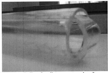
In the second iteration of this design, the tape is preloaded by two ratchets, creating a seal at the distal end of the scope. The 0.0005" thick mylar tape is used once again in this design iteration. The tape progresses approximately the diameter of the laparoscope with each actuation. The tape unwinds from the clean spool and the pawl for the clean ratchet prevents unwanted loosening of the tape by retaining tension at all times. A new, curved tip guide was designed to more effectively guide the tape across the lens without tearing or otherwise distorting the tape as it is pulled across the lens. This new tip guide, seen in Figure 5, is made of transparent, injection molded liquid crystal plastic and places over
the distal end of the scope. This allows for sealing of the laparoscope lens, so that no debris will contact the actual scope lens. The contour of the cap guides the tape smoothly over the distal lens tip, so that with each actuation when the dirty spool pulls in the tape, the tape at the end of the scope is spooled over the lens. With this design, the sheath does not need to be indexed forward and back again to seal the tape over the tip. Thus, the tape never loses contact with the contoured cap at the distal end of the scope. This feature effectively seals the tape around the distal end of the scope, preventing any liquid or solid debris from getting between the tape, tip guide and the laparoscope.
Figure 5: Curved, transparent tip guide; over the scope and inside the protective sheath. The new lens cap and sheath actuation mechanism work together to improve on the first design. The second design eliminates the dynamic movement of the sheath, prevents any distortion or tearing of the tape, and maintains a seal over the lens throughout the operation of the device.
3.3 Dimensioning and Tolerancing
In order to determine the correct dimensions and tolerances of the cap and sheath used in the device, a number of appropriate measurements were taken. Four scopes at Beth Israel Hospital, all 5mm manufactured by Stryker, were measured using a micrometer four times each to determine the outer diameter and tolerance range. Running statistical analysis, the outer diameter was determined to be 4.974 mm ± 6.3 x 10⁻³ mm. Likewise,
seven cannulas were measured four times each and the inner diameter was determined after statistical analysis to be 5.956 mm ± 1.80 x 10⁻³ mm. Converting to inches this gives a scope OD of 0.196in ± 0.00025in, a cannula ID of 0.234in ± 0.0001in and an annulus with a gap of 0.019 inches.
For the requirement of a removable cap that would stay in place during operation, the inner diameter of the cap was calculated using a locational clearance fit. Using the appropriate tables in Shigley's Mechanical Engineering Design [7] the cap inner diameter was set at 0.197 inches.
Due to the limits of manufacturing ability, the wall thickness of the clear plastic protective sheath could be no smaller than 0.004 inches. The outer diameter of the sheath was determined by using a loose running fit classification to insure that the device could be easily inserted into the 5 mm cannula. Again, using the appropriate tables in Shigley's Mechanical Engineering Design [7] the outer diameter of the sheath was set to be 0.231 inches.
Taking the four dimensions as given; cap ID, sheath ID, sheath OD, and cannula ID, the following equation (1) was used to determine the remaining critical dimensions. See Appendix E for a definition of variables. These calculations include a mylar tape
thickness of 0.0005 inches. Additionally, the thickness of the cap, teap, was maximized for ease of manufacturing through an injection molding process.
IDcannuia - ODcope -2(0.002in + tgap + tap +tcapslp+ tsheath) = 0.00in (1) Note: the 0.002in is comprised of the tape thickness plus a 0.00075in gap on either side of the tape for free sliding. tgap is the space between the cannula and sheath, and tcapslip is
the space between the scope and the inner diameter of the cap in accordance with the locational fit.
The tolerances of each piece were set so there would be no jamming of parts inside the trocar, and insure that positive thickness of every part was maintained. The final
dimensions and tolerances of each part are listed below in equations 2 through 5.
ODsheath = IDcannuia -2 tgap =0.231in + 0.000in - 0.001in (2) IDshh I sheath =ODset =O sheath -2tset ~ sheath-= 0223in + 0.O0lin -0.O0in (3)
IDcap=0.197in + 0.0005in - 0.0005in (4)
ODcap=IDcap -2 tcap =0.219in + 0.000in - 0.001in (5)
3.4 Actuation
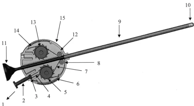
A two-ratchet actuation system eliminates the need for a moving sheath, and reduces the part count and assembly complication found in the first design. Figure 6 illustrates the entire system, and the numbers that label the parts in the figure are referenced in this description of the ratcheting mechanism.
13
15
14 12 6 2 3 4 5 1Figure 6: Completed assembly with labeled components.
The dirty tape is actively wound around a spool, which is part of the dirty ratchet [5], in conjunction with a dual ratchet system that allows the clean spool, attached to the clean ratchet [13], to rotate by pulling the tape [7] when the actuator [1] is depressed. The dual ratchets preload the tape by preventing the movement of the spools when the handle is released. A spring [2] is compressed between the actuator [1] and the casing [15] to provide the restoring force to bring the actuator back to the up position. When the actuator is pressed, a pawl [4], which is inserted into a slot in the actuator tip [3] presses the dirty ratchet [5] which rotates and pulls the tape [7] moving the dirty section of tape out of view of the laparoscope. When the actuator [1] is released, both the dirty and clean pawls [14, 6], which are affixed to the case [15] via slotted features in the casing, prevent the ratchets [13, 5] from rotating in the reverse direction. This maintains a fixed tape [7] position over the lens and ensures that the tape [7] advances in only one direction. The protective sheath [9] is in place once more in this design to guide the tape up to the distal lens of the scope. In order to direct the tape from the clean ratchet [13] into the sheath, and again from the sheath [9] to the dirty spool on the dirty ratchet [5], the tape is guided around rollers [8, 12] that will rotate freely with respect to the casing [15].
3.5 Design Considerations
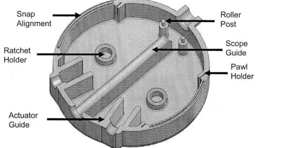
The case was designed with ease of manufacture and assembly in mind. Key features of the case design, labeled in Figure 7, include the snap alignments, ratchet holders, actuator guide, roller posts, scope guide, and pawl holders. The case is designed with symmetry so that it can mate to an identical part which is rotated 180 degrees, allowing one mold to produce both the top and bottom halves of the case which snap together. The ratchets slide into the ratchet holders, the pawls slide into the pawl holder grooves, the rollers
slide over the roller posts, and the actuator is kept in correct orientation with respect to the ratchet by the sidewalls of the actuator guide.
Snap -Alignment Ratchet Holder Actuator Guide Roller - Post Scope Guide oPawe Holder
Figure 7: Case design features.
Similarly, the ratchets and rollers were designed to be multiple uses of the same parts, so that producing a complete device would require only one mold for both ratchets and one mold for both rollers.
3.6 Analytical Model
A thorough analytical study was conducted to analyze the magnitude of the forces acting on the critical pats in the design.
A free-body diagram of the forces acting on the clean ratchet was constructed as illustrated in Figure 8. The normal and friction forces of the stationary pawls were calculated using equations 6 and 7, respectively, with the material properties and dimensions of the pawls and the ratchet teeth found in Appendix E.
F Nsp ~- Npaws *ES *w *t 3 *3i,
4*L P
FfSP =FS*S F, Nsp sp (7)
A system of equations was then developed to solve for the unknown tape force and reactionary forces of the ratchet axle in the x and y-axis.
F,= F,,e * cos(Oae)+±FRBx Fsp * cos(Os, -0, )+ FNsp *sin(Osp r 8
IF, = Ft,, * sin(Otp,)+ FRBY -F- * sin(O,, -,)-FNp *co sp (9)
E r = -Fp * Rap + F, * Rgea, + FRB FRBY2 * R., * = 0 (10)
Ftape
Figure 8: Free-body diagram of clean ratchet.
A free-body diagram of the forces acting on the dirty ratchet was constructed as illustrated in Figure 9. The normal and friction forces of the stationary pawls were calculated using equations 7 and 8, respectively, with the material properties and dimensions of the pawls and the ratchet teeth. The tape force for the dirty ratchet was calculated using equation 11 for a material sliding over a curved surface with the clean ratchet tape force as the holding force.
Fiae2 = FtaP * e"tap *ape (11)
The peak tape force required for the dirty ratchet to rotate the clean ratchet was found to be 1.5N. For a tape width and thickness of 0. 14in and 0.0005in, respectively, the peak stress in the tape was calculated to be 34MPa, well below the 55MPa yield stress of boPET.
A system of equations was then developed to solve for the unknown actuation force and reactionary forces of the ratchet axle in the x and y-direction.
ZF,x = Fape2 * cos(tape)+ FRBx +F,* cos(,,O -0,) FNP*sin(sp r)+Fac *cos(Oac )=0 (12)
XF= Fape2 *sin(Ota,)+FRBY +F ,*sin(0, -O,)+FNP*cos(- r)+Fc *cos(act)=0 (13)
SrFape2 *Rtape +F, *Rgea, + FRBX2 +FRBY2 * Raxle * Fact * Rger = g- 0 (14)
Fact
FF
pes
Figure 9: Free-body diagram of dirty ratchet.
The force of the spring and the input force at maximum actuator displacement were calculated using equation 15 and 16. The input force required to actuate the device, illustrated in Figure 10, was calculated to be 4N. This input force is less than one pound and is low enough for a surgeon to provide during surgery without difficulty.
Fspring =ks *act Finput Fact +Fspring
(15)
(16)
Finput
3.7 Prototyping
For the purpose of rapid prototyping, 3D printing was the method of choice. It enabled the design, which had been developed in Solidworks, to go from a digital model to a physical model in a short period of time. The cases, ratchets, and linear actuator were all
successfully produced close to the desired dimension, requiring only minor sanding to have the desired fits. The inside of the 3D printed prototype can be seen in figure 11.
Figure 11: 3D printed prototype.
Due to manufacturing cost constraints, the tip guide of Design 2 had to be 3D printed, and thus could not be made transparent. To test Design 2, the tip guide design was
compromised and a hole was made in the cap in order to see through it. However, having this hole in a solid-color cap, rather than using the transparent cap without a hole that Design 2 calls for, made testing difficult. As will be described, this left the possibility of the tape deforming as it goes over the guides on the tip. This is likely due to the structural support only along the sides of the cap where the hole was not placed.
4 Testing
4.1 Actuation and Visibility
Testing of the first design occurred at Beth Israel Deaconess Medical Center's Carl J. Shapiro Simulation and Skills Center. These tests were preformed to insure that the functional requirements were met, and are detailed in Appendix F. This section focuses primarily on testing preformed with the new design.
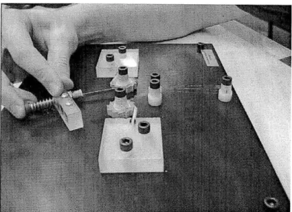
Preliminary actuation and visibility testing of the new prototype consisted of assembling the device with the endoscope inserted, as seen in Figure 12. Upon insertion, the tape
successfully unwound as predicted when the scope was pushed through. The tape at the end protecting the camera lens was then dirtied, an image was taken through the scope, the device was actuated, thereby advancing the tape, and again an image was taken. The result, as seen in Figure 13, was a complete restoration of vision after a single press of the button.
Figure 12: Assembly of device with endoscope inserted.
Figure 13: Visibility testing with natural light; image through scope with dirtied tape (left) and image through scope after dirty tape advanced (right).
Further testing of the device occurred at Rhode Island Hospital's pig laboratory, sponsored by the Minimally Invasive Gynecological Surgery unit at Newton Wellesley Hospital and Ethicon Endo-Surgery. Cleaning efficacy and functionality of the Design 2 device took place in April 2010, and some testing was completed by two surgeons
working inside a porcine abdomen. The porcine testing proved that the tape actuation method for Design 2 is effective. The dual ratchet system effectively advanced the tape 100% of the time the surgeon pressed the plunger in for actuation. However, due to the limitations of the 3D printed cap, the tape deformed as it went over the guides on the tip. The light source that was required for the camera to see inside the body created glare on the tape, so that every defect in the tape reflected the bright light back to the lens, as illustrated in Figure 14. This deteriorated the quality of the images obtained.
Figure 14: Visibility testing with scope light; image of video output without tape (left) and image of video with tape (right).
This indicated that the tape needs to go directly against a contour near or on top of the lens surface in order to prevent this glare from the light source. The two surgeons present at the porcine test provided generally positive feedback for the device, but indicated that they would prefer a smaller casing size length, as it would allow the scope to be inserted further in the event of larger patients.
4.2 Sterilization
In order for the device to be practical for use in the operating room, an appropriate sterilization method had to be chosen. Since a large portion of the device is made of polymer materials that can be damaged by high temperatures, traditional autoclave steam sterilization was found to be an impractical sterilization method. Other available sterilization methods include ethylene oxide (EtO) gas, Sterad@ or hydrogen peroxide gas, and gamma irradiation. EtO and hydrogen peroxide gas sterilization processes require that the surfaces of all components of a device be exposed to the gas. The internal geometry of this device is relatively complex, especially when considering the tightly-wound tape spools. Therefore, exposing the full surface area of the device would be very difficult, making gas sterilization methods impractical for this device. Gamma irradiation was chosen as the most probable sterilization method for this device for its ability to penetrate complex devices and sterilize a variety of polymers without degrading mechanical or visible properties.
To confirm that the device can be sterilized using gamma irradiation, each component in the design had to be considered individually. Since gamma irradiation is widely accepted as safe for sterilizing metals used for mechanical applications, the metal components of the device were considered appropriate for the chosen sterilization method. Many opaque thermoplastics, such as polyether ether ketone, have been validated for use in
medical devices that are sterilized using gamma irradiation. Therefore, it was determined that the purely structural polymer components of the device, including the handle, coupler piece, and casing, are appropriate for gamma sterilization. Finally, the shielding tape was evaluated. A manufacturer of boPET and a large gamma sterilization contractor independently verified that boPET film has been sterilized using gamma irradiation at high radiation dosages with no significant detriment to mechanical or visible properties. Therefore, it was determined that the shielding tape would likely withstand gamma sterilization. Further testing is needed to fully validate the device for gamma sterilization. A sterilization study including many copies of the finished device will be able to determine the correct radiation dosage to fully and safely sterilize the device.
5 Business Considerations 5.1 Cost
Production costs for the device were estimated at 8.50 USD/unit before overhead. Compared to the costs of the previous design of 20.45 USD/unit, as outlined in Appendix G, this is a substantial reduction obtained by focusing on design for manufacture and assembly. This estimate assumes high-volume (>10K parts/year) production of plastic components from injection-molded ABS, commercial off-the-shelf springs and tape, and custom-extruded sheaths. Assembly time was estimated to total 0.1 hours/device after the redesign for manufacturing and assembly while gamma sterilization and packaging is expected to cost 4 USD/unit. Additionally, these estimates include wages competitive with the US labor market. Table 1 shows the cost breakdown for the components of the design.
Table 1: Estimated cost breakdown of device.
Costs Per part ($)
$15/hr assembly (O.1hrs total) $1.50 $20/lb ABS (0.1 lbs total) $2.00
Sheath $0.45
Metal Parts (spring, pawls) $0.50
Tape $0.05
Sterilization and Packaging $4.00
Overhead $8.50
TOTAL $17.00
-100% Gross Margin $17.00
5.2 Competitors
There exist several competitors currently on the market or still in development that seek to clean the lens of the camera used in laparoscopy. The FloShield is a device that uses a constant fluid flush to remove fog and some liquid debris through continual cleaning. However, we feel confident that our product is more versatile in being able to remove solid and liquid debris in addition to fog. The EndoClear is a product that provides a clean wiping surface in the body cavity during surgery. Instead of removing the camera from the body to wipe off debris, the surgeon simply wipes off debris on the sponge from the EndoClear. This device deposits an extra piece of hardware in the body, increasing risk to the patient, which is unacceptable as a functional requirement in our design. Another competitor is New Wave Surgical's D.H.E.L.P., an extracorporeal tool to prevent fogging of the camera during laparoscopic procedures. It works only outside the body, and to clean the lens, the surgeon must still remove the camera, which results in a total loss of visibility in the body cavity. The only active competitor on the market appears to be the Medtronic EndoScrub, which connects to the available gas and saline reservoirs and uses a fluid flush actuated by a foot pump to clean the lens. However, the EndoScrub is not currently used in laparoscopy-it is primarily a device for ear nose throat procedures.
6 Conclusion and Future Work
While further testing is required to refine its design, the current embodiment of the device fulfills the majority of functional requirements that were established at the beginning of the design process. The device fits well within the spatial limits of the operating workspace. Functioning as a self-contained add-on to existing scopes, this device requires no outside hook-ups to insufflation or power sources, and thereby eliminates the need for additional operating room infrastructure. While the previous prototype quickly and effectively removed 100% of liquid, solid, and gaseous debris from the lens, further testing of the most recent prototype is planned. Testing must be conducted to ensure that the newly preloaded tape-lens cap interface will serve to inhibit the presence of debris between the tape and the cap. Finally, future work will focus on improving visual robustness to surface defects in the tape as the current design has shown some tendency for scratches and/or flaws in the tape to reflect light from the scope source.
More exhaustive and quantitative tests are planned to gauge the feasibility of full-scale device sterilization, the amount of vision obstruction through the tape, and the versatility of cleaning various debris from the end of the lens. Ergonomic tests will be conducted to gauge surgeon preference as to the size and position of the product casing. Other steps for improving cost and marketability include designing various sheaths and lens cap mechanisms for compatibility with scopes of various lengths, diameters, and tip angles. The new device requires less than one minute to assemble. The use of repeated parts and snap fits in the design of the casing, as well as the improved tape-feeding mechanism, reduced the time of assembly dramatically from an assembly time of 20 minutes in the previous prototype. Most of the previous prototype's assembly time was related to
inserting the tape into the tip guide, threading it through the sheath, and wrapping it securely around the spools inside the casing. The feeding of the tape into the device in the most recent prototype was reworked so that the tape just needs to be placed on the clean spool and secured to the dirty, or take-up spool, the lens cap put onto the lens, and the camera inserted. The latest prototype no longer uses a cam and moving shaft mechanism to provide tension for the tape over the lens, and thus many of the complications, risks, and parts involved with the previous prototype were eliminated.
Future development of this product will need to include tests of injection molded parts, particularly the lens cap. The design of the lens cap calls for a transparent polymeric cap, something that could not be rapidly prototyped with the technology and time available. By using injection molding liquid crystal processes, the lens cap could be made transparent, and the casing, ratchets, and plunger could be made cheaply and quickly. In the future, the aspiration for a lens cap integrated into the lens of the scope itself is of utmost promise. This will work well with the most challenging aspect of the design which is a clearance between the scope and the standard 5 mm cannula of only 0.019 inches. An integrated lens cap can be completely contained within the original scope outer diameter and leave significantly more room for the protective sheath and tape to operate. However, this solution aside, a possible countermeasure to this problem is to require the use of a slightly larger cannula, of inner diameter of 8 mm. This size cannula is small enough to avoid the use of sutures to seal the incision made for the camera port. Currently, the device is designed for a particular scope length, diameter, and tip angle. However, given the simple elegant design, the device can be easily scaled to become a future line of products that can be adapted to fit all scope lengths, diameters, and tip angles.
Acknowledgments
This product was developed as a part of the MIT courses 2.75: Precision Machine Design and 2.752: Design of Mechanical Products. The authors would like to thank the former 2.75 team of Sterling Anderson, Nikolai Begg, Kevin Farino, and Julia Zimmerman for developing the first iteration of this device. The authors would also like to thank Professor Alex Slocum, Dr. Julio Guerrero, Dr. Keith Isaacson, Conor Walsh, Nevan Hanumara, Dr. Joan Spiegel, Dr. Amanda Bush, Dr. Chris Reichman, and Christopher Schantz. We are also grateful to Rhode Island Hospital, Newton-Wellesley Hospital, and Beth Israel Deaconess Medical Center for the use of their facilities. Finally, we would like to thank Lynn Osborn and Dr. Tom Brady of the Center for Integration of Medicine and Innovative Technology (www.cimit.org) for financially supporting this course and project. CIMIT support comes from DOD funds with the FAR 52.227-11.
References
[1] Champault, G; Cazacu, F; Taffinder, N. "Serious Trocar Accidents in Laparoscopic Surgery: A French Survey of 103,852 Operations." Surgical Laparoscopy, Endoscopy, and Percutaneous Techniques. Vol. 6, Num. 5. October 1996.
[2] Reich, H; DeCaprio, J; McGlynn, F. "Laparoscopic Hystorectomy." Journal of Gynecologic Surgery. Vol. 5, Num. 2. Summer 1989. pp. 213-216.
[3] Cadiere, G; Himpens, J; Germay, 0; Izizaw, R; Degueldre, M; Vandromme, J; Capelluto, E; Bruyns, J. "Feasibility of Robotic Laparoscopic Surgery: 146 Cases." World Journal of Surgery. Vol. 25, Num. 11, Nov. 2001.
[4] Zheng, B; Martinec, DV; Cassera, MA; Swanstrom, LL. "A quantitative study of disruption in the operating room during laparoscopic antireflux surgery." Journal of Surgical Endoscopy. Vol. 22, Num. 10. October 2008.
[5] H. Akiba, "Observation window washing device of endoscope" , October 28, 2003. [6] G.D.I. Grice and J.C. Miles, "Disposable scope cleaner and method of using same",
December 28, 2006.
[7] Budynas, R; Nisbett, J. Shigley's Mechanical Engineering Design. Eighth Edition. New York, New York. McGraw-Hill Companies, Inc. 2008
Appendix A Functional Requirements
Table 2: Functional requirements and design parameters. Rank Functional Parameter Metric
1 Does not increase risk to Incidence of scope
patient related complications
Provides adequate visibility through lens and improves visibility in the case of partial
or full lens obfuscation
Obtain FDA 3 Meets FDA standards classification and
certification
Works with 5mm trocar 4 Meets industry standards and does not require an
incision of >10mm
5 Risk to patient in event of
complications minimized
Procedure modification or D
6 dirpio disruption minimizediimzdDoctor training time Money spent by
7 Works with existing hospital to integrate the
technology product less the cost of
the product
Minimize time of obscured Frequency of cleaning
8 . and duration of
cleaning cycle Money spent by
9 Minimize cost hospital to use the
product
10 Versatility of cleaning Types of obstructions the system can remove 11 Minimal interference with Change in available
Appendix B Range of Motion
During a laparoscopic procedure, operating room staff frequently manipulates the scope both along its axis and about the cannula pivot to see areas of interest in the insufflated abdomen. This scope placement is conducted through a single port, and may be completely described by an axial translation (r), an inclination angle (a), an azimuthal angle (w), and a roll angle (p). This coordinate system is illustrated in Figure . Directions most sensitive to motion and most utilized when manipulating the field of view include the axial direction (r), the inclination angle (a), and the azimuthal angle (I).
Roll angle about the scope axis (y), in contrast, is less utilized and therefore less sensitive to interference.
Coupling the shielding device to the scope limits the achievable range of motion along each of these coordinate dimensions. The degree of this limitation in angular dimensions varies with scope insertion -- when the scope is inserted little, the shielding mechanism disturbs the range of motion less; for large insertion, this impedance becomes more significant. For the tests illustrated below with Design 1, impedance was calculated for an 11.8 in (30 cm) scope inserted 5 inches (12.7 cm) into the abdomen.
Figure 15: Model of scope placement; virtual, life-sized model of an insufflated female abdomen.
Table 3 contrasts the scope's maximum range of motion with and without the lens shielding mechanism. Note that any motion lost is lost only at extreme deflections. For instance, the scope must be inserted deeply into the abdomen (r large) or angled upward nearly as far as possible (a large) before the shielding mechanism begins to impede motion. Also note that with the exception of the axial direction, scope motion is inhibited very little by the presence of the shielding mechanism.
Table 3: Range of motion; 30 cm scope with and without the shielding mechanism.
i DMaximum Range at 12.7 %
Dimension Description Range cm Insertion Change r Translation along scope 30 cm 23.4 cm 23 %
axis
Elevation angle from 90 deg. 79 deg. 12 % vertical
Azimuthal angle (about 360 deg. 343 deg. 4.6 % vertical axis)
Roll angle (about scope 360 deg. 317 deg. 12 %
Appendix C Concept Selection
Strategies developed to address the functional requirements, summarized in Appendix A, were assessed using the Pugh chart shown in Table 4. A device with a similar purpose, the EndoScrub was chosen as the control in Pugh chart evaluation. This device uses a combination of fluid rinse and suction to clean the lens of debris. Some of the strategies evaluated are similar to those found in prior art, such as using fluids to wash debris off the lens or using a mechanical device to wipe debris off the lens, entitled "fluid-gas" and
"passive wiper" respectively in Table 4. Several novel strategies were also considered. The "sliding shield" strategy involves covering the lens with a piece of clear plastic that can be removed and replaced when dirtied by sliding the tape across the lens, similar to the paper on a doctor's examination table. Another strategy, entitled "onion," uses a stack of false lenses that are successively removed as they are dirtied. The strategy entitled "weeping lens" uses a hydrophilic lens material that is kept constantly covered by a thin layer of saline kept clear by continually dripping new saline across the lens. The final strategy evaluated uses vibration to shake debris of the lens. The Pugh chart evaluation found that the sliding shield strategy best addresses the functional requirements.
Table 4: Pugh chart evaluation of selected concepts. Slidin
Endo Fluid Onio Weepin Passive Vibratio Scrub -gas Shiel g Lens Wiper n
sterilizable 0P0__ 0 0 0 -l workspace clutter 1 1 -1 1 1 1 visibility 0 0 -1 -1 1 0 0 compatibility 0 0 1 1 0 1 0 risk of failure 0 0 -1 -1 P -1 0 no procedure0 1 1 0 1 -1 0 disruption cleaning versatility 0_0 1 1 0 -1 ?
cleaning cycle time 0_0 1 1 1 0 -1
cost 0 0 1 1 P 0 -1 ease ofuse 0 0 0 0 1 -1 0 visibility during0 0 1 0 1 0 0 cleaning implications of failure 0 0 0 1 0 -1 1 TOTAL 0_0 3 0 2 -3 -3
Selection
Given the parameters of a shielding strategy, the goal of the concept selection stage was to create the simplest machine that would achieve the goal of restoring clear vision to the surgeon. Many solutions were considered, including a fluidic weeping lens, layered shields, and a spooling shield. Each was evaluated in terms of its feasibility and performance through bench level experiments.
The bench level test on the ability to spool polyethylene proved that it was capable. Different thicknesses, including 0.0005 in, 0.001 in, and 0.005 in of polyethylene were tested. The material was run through a sheath containing a phantom scope and translated through the mechanism without sheering, binding, or crazing. Further tests were performed on the materials in relation to this concept. Each shielding material was tested for its ability to be drawn across the face of a -5-12mm endoscope. In these tests, thicker materials performed much better than thinner materials, exhibiting less crazing and stretch-deformities while maintaining sufficient flatness across the surface of the lens (so as to avoid optical distortion). Taken together with the results of transparency testing, this suggests that a single layer of thicker, stiffer, and non-self-adhesive material is
best-suited for a spooling shield embodiment of this strategy.
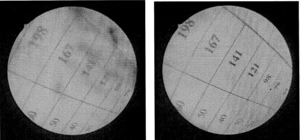
The layered shielding concept did not fare well. The visibility through multiple layers was tested using the vision chart seen through a 4mm-thick acrylic lens; figure 16 (Left).
Figure 16: Vision test; through 4mm acrylic lens (Left) and four 05mm layers of polyethylene (Right).
Although clear vision was obtained through eight layers of the .01 thickness, the polyethylene was self-adhering and did not clean very well. Opacity was aggravated with additional layering. The vision was obscured after only four layers, proving this concept inefficient. Figure 16 (Right) shows vision through four .05mm layers. Second, the thicker materials used in this study did not self-adhere and were therefore more difficult to layer tightly. Without a tight seal between shielding layers, air pockets form, reducing vision and potentially trapping debris. These results suggest that thicker materials should be used for spooling and re-circulating embodiments of the shielding strategy rather than for discard-type approaches.
The spooling mechanism faired best in these large scale tests, proving the most effective means of restoring vision. The spooling mechanism eliminates many of the risks associated with the other concepts. The unknowns and increased complexity surrounding the fluidic weeping lens and the layered lens did not outweigh the potential benefits the concepts offered and lead the development team to pursue the spooling mechanism as the concept of choice.
Appendix D Design 1
Tape Guidance and Sealing
A continuous strand of shielding tape was chosen to protect the lens tip from various sources of obfuscation. The tape enters the cannula alongside the laparoscope, travels linearly down the length of the scope, over the tip of the scope, back up the other side of the scope and out the top of the cannula. The annulus formed by the inner diameter of the cannula and the outer diameter of the scope, representing the working space in which the tape travels down to the tip of the scope and back, has a thickness of 0.017 inches. Therefore, this clearance is fully occupied by a mechanism to guide the tape, and the actuation mechanism for the tape is located above the cannula. The shielding tape is protected from friction against the cannula by a thin-walled stainless steel sheath. At the distal end of the sheath, where the scope passes beyond the tip of the cannula, the sheath holds the tape flat against the sides of the scope and protects it from getting dirty before reaching the tip of the scope.
At the tip of the scope, the tip guide piece guides the tape over the lens and back into the other side of the sheath. The guide is a molded plastic part that is glued to the end of the sheath. The tip guide also clamps down on the tape when the lens is not being cleaned, in order to prevent creasing or buckling in the tape surface and to preserve the clarity of the surgeon's view. Activation of the tip guide is described in the next section. Figure 17 shows the tip guide assembled to the distal end of the sheath.
Figure 17: Tape guide mechanism; tip guide and protective sheath at distal end of scope. The shielding tape is 4.6mm wide (for 5mm diameter scopes) to ensure that the entire lens is protected. Biaxially-oriented polyethylene terephthalate (boPET) was chosen for as the shielding tape material because of its high yield strength and commercial availability. Since the tape travels a distance over 100 times its width and is subjected to a variety of shear and normal stresses, boPET is an appropriate material for the tape.