Design of a Miniaturized Hall Thruster for
Microsatellites
by
Vadim Khayms
Submitted to the Department of Aeronautics & Astronautics
in partial fulfillment of the requirements for the degree of
Master of Science in Aeronautics & Astronautics
at the
MASSACHUSETTS INSTITUTE OF TECHNOLOGY
May 1997
@
Massachusetts Institute of Technology 1997. All rights reserved.
Author ...
Certified by...
Accepted by.
...
/
...
Department of Aeronautics & Astronautics
May 23, 1997
... ...Manuel Martinez-Sanchez
Professor
i
Thesis Supervisor
"1
Jaime Peraire
Chairman, Departmental Committee on Graduate Students
JUN 19 1997
A~RO
Design of a Miniaturized Hall Thruster for Microsatellites
by
Vadim Khayms
Submitted to the Department of Aeronautics & Astronautics on May 23, 1997, in partial fulfillment of the
requirements for the degree of
Master of Science in Aeronautics & Astronautics
Abstract
Microsatellite technology has become increasingly popular in recent years as it can offer significant cost savings, higher reliability, and is generally more affordable for a large variety of commercial applications. Since many microsatellite missions require considerable propulsion capabilities, miniaturization of the propulsion subsystem is critical in the design of most miniature spacecraft. A Hall thruster has been ana-lyzed, designed, and manufactured for operation at considerably lower than standard power levels. This particular engine was chosen as one of the most mature electric propulsion devices. In an effort to miniaturize the thruster, a number of complica-tions have been encountered. Of the most troublesome were higher magnetic field
requirements, larger internal heat fluxes and temperatures, and complexities associ-ated with manufacturing of the various miniaturized components. These and other related issues were addressed and analyzed in this work. The results of our findings are reflected as major changes to the conventional Hall thruster design. The thruster has been manufactured and tested for operation in a vacuum chamber. Preliminary assessment indicates excellent performance matching with the existing devices, hence opening new opportunities for the use of microthrusters in a variety of spacecraft applications.
Thesis Supervisor: Manuel Martinez-Sanchez Title: Professor
Acknowledgments
The successful completion of this project is attributed to the help and support from a number of resourceful individuals.
First, I would like to express gratitude to my advisor, Prof. M. Martinez-Sanchez for his patience, insight, and continuous support throughout the two years of this work. His immense knowledge of absolutely everything and his willingness to share this knowledge with his students has been extremely helpful.
I would like to thank Mike Socha of Draper Laboratory for his financial and technical support throughout the project. As a manager, his ability to find and involve appropriate technical personnel was quite helpful on a number of occasions. I am also grateful to the machine shop personnel of Draper Laboratory, specifically to Edward McCormack for his valuable advice and manufacturing of some of the
low-tolerance components for the microthruster.
I would also like to thank Bohus Ondrusek for his help in the testing phase of the microengine. Always eager to help, his experience with cathodes was extremely valuable in resolving some of the difficulties in the preliminary testing due to poor cathode emission.
I am also grateful to the engineering staff of the Dexter Magnetic Materials Divi-sion (Permag) for their support in the design and simulation of the magnetic circuitry and assembly for the microthruster. Their capabilities in performing seemingly im-possible tasks were quite impressive.
Finally, I'd like to thank some of the faculty, staff members, and students of the Aeronautics & Astronautics department of MIT including Prof. Spearing, Prof. McManus, Prof. Breuer, Dick Perdichizzi, Donald Wiener, Adam London, Mike Fife, Bernard Asare, Reid Noguchi and many others for their technical assistance, advice, and support.
Contents
1 Introduction 7
1.1 M otivation . . . 7
1.2 Objective ... 8
1.3 Methodology ... 8
1.4 Hall Thruster Operation ... 9
2 Scaling Model 11 3 Thruster Design 17 3.1 General Considerations ... 17
3.2 Magnetic Circuit Design ... 18
3.2.1 Vacuum Insulation ... 24
3.3 Thermal Design ... . ... .... . . . . ... 24
3.3.1 Analytical Thermal Model of the Anode . ... 26
3.3.2 M aterial Selection ... 28
3.4 Cathode Design ... 29
3.5 Final Design ... .. 31
4 Operational Testing 32 4.1 Testing Facility ... . . .. . .. .. .. ... . .. . .. . .. . . .. 32
4.2 Experimental Results and Evaluation . ... 33
List of Figures
1-1 SPT schem atic .... .. .. . . .. ... .... . .. . ... . . . 3-1 Magnetic circuit model ...
3-2 Magnetic circuit geometry (all dimensions in mm) . . . . 3-3 Magnetic circuit simulation (Dexter Magnetic Materials Division) 3-4 Magnetic field profile (gap) (Dexter Magnetic Materials Division) 3-5 Vacuum gap insulation .
Anode insulation assembly ... . ... 1D thermal model ...
Anode configuration ...
(a) Anode temperature profile; (b) Radiative Final design schematic . . . .. Testing facility . ...
I-V characteristics . ...
Thruster Efficiency vs. Specific Impulse. ..
Thruster efficiency vs. flow rate ...
. . . . 25 . . . . . 26 heat fluxes . 20 . 22 . 23 . 23 3-6 3-7 3-8 3-9 3-10 4-1 4-2 4-3 4-4 . . .
List of Tables
Chapter 1
Introduction
1.1
Motivation
A large number of potential microsatellite missions such as constellation deployment, orbit maintenance, and formation flight of a local cluster heavily rely on the propulsion subsystem. Although much attention has been recently given to the design of various microelectronic components, very little effort has been devoted to the miniaturiza-tion of the vital propulsion subsystem. A significant reducminiaturiza-tion in manufacturing, maintenance, and launch costs is the main incentive for producing and flying small scale satellites. For instance, constellation flight is an effective way of diminishing the total cost. This is mainly due to the capability of redistributing functionality among different spacecraft, thus reducing the complexity of each individual satellite, and increasing the reliability of the overall system [4]. The reduction in size and therefore weight of each satellite also results in lower launch costs per satellite. Even if the functionality were reduced in proportion, the lower unit costs still hold po-tential for broadening the user pool and opening up applications previously thought impractical. Production of smaller satellites results not only in the reduction of their complexity, but also facilitates a tremendous increase in the design efficiency. This lowers the development lifecycle, facilitates mass production, and hence, significantly lowers associated costs. In addition to higher reliability, larger thrust to weight ra-tio, an intrinsic property of all small-scale devices, is quite attractive, especially for
long-term interplanetary missions. Because of the numerous advantages of miniature spacecraft, it is essential to develop and incorporate suitable propulsion technologies into the microsatellite industry.
1.2
Objective
The selection of a particular propulsion device was primarily based on the specific mission objectives that nowadays demand increasingly better propulsion capabilities (e.g precision positioning and pointing for interferometry). Since a large number of potential missions such as constellation flights, north-south station keeping, drag makeup, as well as many other applications, optimize in the high Is, - low thrust regime, electric propulsion becomes a natural competitor for a majority of these missions. A Hall thruster, being one of the most mature electric propulsion devices [2], has been selected for our studies. Although somewhat less efficient than a state-of-the-art ion engine, its relative simplicity and compactness become quite attractive, especially at small scale. Hence, the objective was set to conduct a feasibility study of constructing and operating a miniature Hall thruster at low power, then to design and build a miniature prototype, and finally test it for operation in a vacuum chamber.
1.3
Methodology
There exist two different philosophies or approaches that could be undertaken in any design problem. One of these is to come up with a new concept, develop new design, manufacture the device, and then test whether the device achieves satisfactory per-formance. The second approach is to examine a similar existing thruster, understand its underlying physical principles and governing phenomena, come up with a simple model describing these phenomena, and then scale down the device, while preserving basic characteristics of the original model. Of the two, the latter approach seemed more appropriate, as it avoids the additional uncertainties associated with operation in different physical regimes. This allows concentration on the limitations and
diffi-MAGNET
PROPELLANT FEED LINE
E e CATHODE
Figure 1-1: SPT schematic
culties that arise upon scaling of the device. Further, this method would yield deeper understanding of the workings of the device and allow necessary modifications to be made to the original model in advance. This would help overcome or eliminate poten-tial difficulties with the new concept. An SPT-100, a Russian built 1.35 kW model of the Hall thruster was used as a baseline for scaling. This model was chosen primarily due to the availability of reliable performance data for various optimal configurations from both experimental and numerical studies. The scaling laws, which are discussed below, were then applied to the existing model to estimate the new parameters of the microthruster. The thruster was manufactured in conjunction with a number of contractors and was subsequently tested for operation in a vacuum chamber. The fine points of the design as well as some of the results of operational tests are presented and discussed in some detail below.
1.4
Hall Thruster Operation
A conventional Hall thruster has the shape of an annular shell with cylindrical sym-metry as shown in Fig. 1-1. During operation, propellant is injected through the back side into the main discharge chamber. The cathode located in front of the channel is heated by an external power source to achieve the required neutralizing current by thermionic emission. A radial magnetic field established across the accelerator channel prevents the electrons emitted by the cathode from streaming directly into
the anode. Instead, they spiral around the magnetic field lines and drift azimuthally between ionizing collisions with neutrals. The magnetic field strength is chosen so that the gyromagnetic radius of the electrons is much smaller than the characteristic dimension of the thruster. Through collisions and turbulent scattering, both primary and secondary electrons can penetrate the magnetic field lines towards the anode, sustaining the discharge in the channel. A potential difference externally applied be-tween the anode and the cathode produces an axial electric field. The two fields set in mutually perpendicular directions result in an electron E x B drift motion in the azimuthal direction, perpendicular to both the electric and the magnetic fields. The qv x B force on the electrons due to this drift balances the electrostatic force on them, and the corresponding reaction on the magnetic assembly transmits the thrust to the body. This is the origin of the generic "Hall Thruster" designation for this device.
The ions are produced by numerous collisions between the neutrals and the elec-trons trapped by the magnetic field. These ions are accelerated in the electric field along the annular channel to exhaust velocities on the order of 10,000-20,000 m/s. The ion beam is neutralized upon its exit from the channel by additional electrons drawn from the heated cathode.
Chapter 2
Scaling Model
This chapter is devoted entirely to the discussion of the physics of the Hall thruster and the scaling laws that result from the basic relations among its characteristic parameters [5]. Numerical estimates of these parameters for a scaled device are then determined and used as a baseline for the design of the microthruster. The main goal of this scaling model is to achieve a reduction in power and the length scale of the device while preserving both the efficiency and its specific impulse (Ir,). In what follows, the electron temperature is assumed constant. This assumption, although not evident at first, will be justified further in this section.
Let us start by considering the effect of the electric potential on the ion exhaust velocity, which is directly related to the specific impulse. The kinetic energy imparted to the ions as they exit the accelerator channel is determined by and is equal to the electric potential energy due to the voltage applied between the anode and the cathode. Hence, in order to preserve Is, we require that the electric potential be invariant under scaling.
All the basic plasma phenomena in the Hall thruster rely heavily on the ioniza-tion process that takes place within the acceleraioniza-tion chamber whereby the neutrals are ionizied in collisions with the electrons. As the size of the device is reduced, all else remaining unchanged, the number of collisions that the electrons and the neu-trals experience with each other as they traverse the effective length of the device is reduced. Thus, in order to maintain the collisionality properties of the plasma,
it is necessary to increase the number density of each species in proportion. This is equivalent to the statement that the ratio of the mean free paths of each of the species to the characteristic length of the device has to be preserved under scaling
= const. (2.1)
L nQL
where n is the particle number density and Q is the collision cross-section. Here we have assumed that the collision cross-section, being a function of the electron temperature alone, remains invariant. Thus, particle densities (both ne and nn) are inversely proportional to the characteristic thruster dimension:
ne, n~ -1 (2.2)
L
Invariance of Te also yields a similar result for the pressure p:
P 1 1 (2.3)
Knowing the particle densities, it is now possible to determine how the mass flow rate of the propellant scales with size:
Th = mincA (2.4)
where c is the ion exhaust velocity and A is the cross-sectional area of the channel opening. Since the number density scales inversely with size and the area scales as the square of the size, the mass flow must be linear in the characteristic thruster dimension:
rh - L (2.5)
We shall now turn to the discussion of the electrical properties of the plasma. The total current in the channel can be deduced from a one-dimensional generalized Ohm's law:
1 dP
j = o(E +- ) (2.6)
where a is the electrical conductivity given by:
S= ee2 mee
(2.7)
and v is the collision frequency, proportional to the neutral number density. Since both number densities scale the same way, a remains invariant, and therefore:
V 1
L L
As an additional mechanism, based on Bohm diffusion across the magnetic field, en2e
16B
(2.8)
(2.9)
which is also invariant, provided both ne and B both scale as 1/L (see below). The electron current then is the product of the current density and the plasma column
area (- L2), hence:
Ie _ L (2.10)
The ion current density on the other hand is governed by the distribution of ionization rates (V - ji = eie), and since the ionization free path remains the same fraction of
length, ~e will be distributed the same way, and its magnitude will scale as nevi/L
1/L2, giving
ji - 1/L (2.11)
(2.12) The previous result suggests that the utilization efficiency, given by:
mili
m!er
r7u- erii
(2.13)
scales as the ratio of the ion current to the mass flow rate, and thus remains invariant, as desired. The total power required for the thruster scales as the product of the
applied voltage times the ion current:
P = VI - L (2.14)
This relationship forms the basis for scaling, as it is the desired power level in the miniaturized thruster that ultimately determines its characteristic dimension.
We can now examine the losses and evaluate the thruster efficiency. The loss of ions to the wall can be estimated as the ion current into the wall times the ionization potential:
Puaii - VBohm neAVi - L (2.15)
where VBohm = kTe/mi. Therefore the overall efficiency, which depends mainly on
the wall recombination losses (P,,a,/P), the ionization-radiation losses, and neutral losses (ru), will remain invariant, as desired.
In order to preserve the electron confinement characteristics by the magnetic field, it is necessary to maintain the Larmor radius ratio relative to the chamber dimension:
rL my - = const. (2.16) L eBL Hence, B - (2.17) L
Although most of the parameters considered above scale with the thruster dimension as desired, the sheath thickness (Debye length) which goes as /Te/ne, scales as V hence violating the general trend. As a result, sheaths will become proportionally bigger as the characteristic dimension is reduced. It is believed, however, that this does not have a strong impact on the general scale invariance as long as the sheaths remain much thinner than the channel width.
Finally, an electron energy equation can be used as a check on the assumption of the electron temperature invariance under scaling. Neglecting for the moment
radiation and elastic losses, the electron energy equation reads:
V (Jehe - KeVTe) = E -je (2.18) e
where he is the electron enthalpy (including ionization), and is invariant if Te is constant, and Ke is the electron thermal conductivity. The general Wiedemann-Franz law states that Ke/a is proportional to Te, the proportionality constant being
- (kB/e 2) for a plasma; since a and Te are invariant, so is Ke. It can be verified therefore that each term in the electron energy equation scales as 1/L2, and the conservation law is satisfied by the same Te at all scales, as assumed. Elastic power
loss to heavy particles also scales (per unit volume) as 1/L 2, as we can easily verify as follows. The energy transfered from an electron to an ion due to an elastic collision per electron is given by:
2m
E = 2m (2.19)
The energy per unit volume per unit time is then:
5e 1
Pelastic = ne L- (2.20)
as desired. Radiative losses deserve special consideration. Due to the preservation of all mean-free-path ratios, the gas opacity will be preserved, and, since radiation is volumetric (optically thin limit) in existing Hall devices, it will remain so upon scaling. The radiative power loss per unit volume will then scale as the ionization rate, 1/L 2, since both, ionization and excitation of atoms are driven by electron-atom
collisions, and photon emission is prompt. Thus, the common practice of accounting for radiative losses by using in the electron energy balance an "effective" ionization energy of 2 - 3 times eVi will remain valid, with the same factor at all scales. Notice that for devices or components where radiation is from the surface only (optically thick limit), radiative power losses per unit volume will scale as 1/L, and will become weaker than other terms in the energy balance when L is reduced.
Parameter SPT-100 I mini-SPT
Power, W 1350 50
Thrust, mN 83 3
Specific Impulse, sec 1600 1600
Efficiency 50 50
Channel Diameter, mm 100.0 3.7
Flow Rate, mg/sec 5.0 0.2
Magnetic Field, T 0.02 0.5
Table 2.1: Scaled Design Parameters
particle flux both result in a significant reduction of the lifetime (- L2). The lifetime
issue has not been given much attention in the design and is the subject for further studies. However, it is important to point out that the lifetime issue at small scale is intrinsic to most of the electric propulsion devices of this type. Although some of these difficulties can be alleviated through the use of erosion-resistant materials or by a geometrically optimized chamber/anode configuration, it is hard to envision a lifetime improvement greater than an order of magnitude from that of the current design.
The results of applying these scaling laws to the existing SPT-100, a Russian built 1.35 kW model of the Hall thruster, are briefly summarized in Table 2.1. The scaling factor was chosen to be roughly 27. This scaling factor corresponds to the power requirement reduction from 1350 W for SPT-100 to about 50 W for a miniaturized thruster. This number, chosen for nominal input power of the microthruster, has no particular significance. Power levels in this range would be suitable for a large number of potential microsatellite missions.
Chapter 3
Thruster Design
3.1
General Considerations
A Hall thruster in its standard configuration consists of a magnet, an insulated plasma channel, an anode, a propellant feed system, and a hollow cathode [6]. Often the plasma channel is thermally and electrically insulated from the surroundings by a layer of high-temperature ceramic that protects the magnets and other components from excessive heating. However, because of the larger heat fluxes involved, internal temperatures may exceed those imposed by the material limitations. By leaving a vacuum gap between the insulator and the body of the thruster, heat fluxes from the channel can be significantly reduced and limited to those mainly due to thermal radiation. Although the latter configuration seems to resolve the heating problem, it raises another point of concern. The manufacturing of the tiny ceramic channel that would have to withstand high temperatures and be resistant to thermal shock, may prove to be extremely complicated. For this reason we have decided to abandon the idea of using an insulator at all, but rather extend the anode further into the channel and conduct most of the heat radiated by the anode through the thruster body out to the surroundings.
This Hall thruster configuration with an extended anode and bare metallic walls is known as TAL (Thruster with Anode Layer). The walls are usually kept at the cathode potential thus repelling electrons trapped by the magnetic field near the exit
of the channel. The reduction of the ionization layer observed in the experiments, a process which is still not completely understood, is usually attributed to this electron bottling effect. Although the physics of near-wall processes in the TAL is somewhat different from that of the SPT, the observed performance characteristics of the two thrusters are known from measurements to be almost identical. A TAL of a given size, however, is known to operate at a slightly higher power than its SPT counterpart. For that reason we have decided to preserve the scaling laws originally developed for an SPT and possibly operate the thruster at a correspondingly higher power level.
3.2
Magnetic Circuit Design
Traditionally, in most Hall thruster designs electric coils are used to generate the required magnetic field. However, as the analysis below suggests, any attempt to reproduce these coils at smaller scales results in a complete failure.
If an electric coil is to be used in a "horse shoe" type magnetic circuit arrangement, the magnetic field in the gap could be easily estimated from Ampere's law:
Bml
Bgg + = PoIN (3.1)
where B9 is the gap field, g is the gap size, t0 is the permeability of free space, and /
is the permeability of iron core. Assuming Ip to be infinite, the electric current that needs to be supplied to the coils would be approximately given by:
B = poIN (3.2)
Since the B-field scales inversely with length this implies that the number of ampere-turns (IN) for the coils must remain constant upon scaling. The total power dissi-pated in the coils scales as the square of the current times the resistance of the wire. Assuming that the current driving the solenoid is drawn from the anode power supply, being in series with the plasma, (traditional arrangement in the existing devices), it scales directly with length. The number of turns required in the solenoid would then
be inversely proportional to L. The wire diameter w would scale as the length divided by the number of turns:
w , L2 (3.3)
Hence, the wire resistance can be written as:
R = pl r) 1 (3.4)
A L3
Therefore, the power dissipated in the coils scales inversely with the square of the characteristic dimension. Since both the effective conduction and radiation areas are simultaneously scaled by a factor of L2 the heat fluxes both scale as 1/L4. For
con-ductive heat transfer, heat flux is directly proportional to the temperature gradient, hence:
1
ATcond (3.5)
Radiative heat transfer flux is proportional to the fourth power of the radiating surface temperature, and therefore:
Trad - (3.6)
L
In either case, this yields extremely high temperatures on the coil surfaces. Such high temperatures can result in severe damage to the insulation, short circuiting between the individual turns, and finally to the complete loss of the solenoid.
A different approach to the problem is to abandon the idea of using electric coils in favor of permanent magnets. Although a number of advantages make them ideal for this application, there is one drawback. Scaling of the thruster dimension leads to a significant reduction in the overall radiative surface area causing larger heat fluxes, and as a result potentially, higher temperatures. The maximum allowable tempera-tures, however, are limited due to the possibility of demagnetization of the permanent magnets. Therefore it becomes necessary to provide for adequate heat escape paths which may substantially complicate both the design and the manufacturing process. Startup problems are possible due to the existence of a strong magnetic field that may prevent the electrons from entering the channel to initiate ionization of the neutrals
-Ho I' H
Figure 3-1: Magnetic circuit model
during ignition. An increase in the required magnetic field poses a question of feasibil-ity of using permanent magnets of reasonable sizes for this application. However, as the analysis below implies, permanent magnets would make a suitable substitute for the electric coils at this size. Anything smaller would require higher magnetic fields which would not be attainable with the existing state-of-the-art magnetic alloys. In addition, higher magnetic fields would result in saturation of the iron core, and hence limit the applicability of permanent alloys in the designs of yet smaller thrusters.
The following configuration was proposed. A single cylindrical shell of perma-nently magnetized material would be used to achieve the required B-field, estimated to range from 0.3 - 0.5 Tesla within the gap. A simplified analysis for preliminary assessment and comparison of the possible circuit geometries and materials to be used for construction is presented below. Assuming a constant cross-section and infinite permeability of the iron core (see Fig.3-1), the Ampere's law around the loop yields
(assuming infinite permeability of any interposed iron):
Bmg
Hmd + =0 (3.7)
where Hm < 0 is the magnetic field and Bm is the magnetic induction within both the gap and the magnet. A linear approximation to the magnetization curve for a
given magnetic material can be written in the form:
Bm Bo Hm + Bo (3.8)
Ho
where Ho > 0 and B0 are the coercive force and the magnetic remanence respectively.
The graphical construction is shown in Fig.3-1 on the right. Eliminating Hm the two equations yield a rough estimate of the resultant magnetic field within the gap.
Bm 1 (3.9)
B0 1 + ( ) (3)
The gap width is limited by the channel opening and the ratio g/d can be held as a fixed parameter. Thus, in order to achieve the required B-field the material of choice would have to meet the following specifications:
* Bo ~ 0.7 - 1.0 Tesla
* Low Bo/Ho, hence, high coercivity (Ho)
In addition, the material would be required to withstand elevated temperatures with-out significant loss of magnetization. Only three materials were identified to be applicable out of a wide selection of magnetic alloys currently available in the mar-ket. Both NdFeB and Alnico magnetic alloys possess excellent magnetic properties, however have low Curie temperature (350 Co) and low coercivity respectively. SmCo alloys, on the other hand, with their high coercivity (9, 000 Oersteds) and high max-imum operating temperature of 275 Co (Curie point of 750 C) were found to be optimal for our application. Attention was paid in the design to the magnetic field profile in the gap. The goal was to prevent any electrons emitted by the cathode from directly entering the channel and traveling towards the anode along a magnetic line. This imposed a constraint on the field geometry such that the adjacent field lines would be everywhere tangent to the anode frontal surface. The field strength was also adjusted in such a way as to obtain a symmetric field profile with respect
Figure 3-2: Magnetic circuit geometry (all dimensions in mm)
to the mid-line of the channel. This is primarily so as to prevent the ion beam from deflecting either away or towards the center-line of the channel. Such a deflection may be a result of non-uniformities in the electric field caused by the presence of electrons trapped in the magnetic field.
Two-dimensional axisymmetrical finite element numerical computations were run for several variations of the proposed geometry, which is schematically shown in Fig. 3-2 (simulation is courtesy of Dexter Magnetic Materials Division). Two SmCo per-manent magnets are used in the design of the magnetic circuit. One of the magnets is designed in the shape of an axially polarized cylindrical shell. It is the main "driving magnet". The second one, consisting of eight arc segments, is polarized radially in the direction perpendicular to the polarization of the main magnet and is used to force the flux into the gap and to shape the field lines to meet our profile specifications. The iron return path is designed to extend all the way around the main magnet to reduce the flux leakage out of the circuit and to help directing the flux into the segmented magnet (see Fig.3-3). The attained values of the magnetic field strength in the gap for this geometry were numerically estimated to range from 0.4 - 0.6 Tesla at the designed maximum operating temperature (250 CO) thus meeting our specifications. The calculated field profile within the gap is shown in Fig.3-4.
Figure 3-3: Magnetic circuit simulation (Dexter Magnetic Materials Division)
48
28
U~.46 . 'A A2, _:
3.2.1
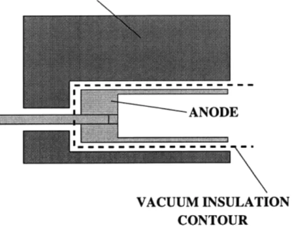
Vacuum Insulation
The internal thruster walls are electrically insulated from the anode by a vacuum gap (as shown in Fig. 3-5) which prevents any discharge that may be initiated due to the presence of a leak, resulting in the accumulation of the neutrals. As the analysis below shows, the gap size scales directly with the mean free path for a given characteristic size, and therefore, vacuum insulation would be effective as long as the mean free path of the neutrals is much larger than the gap size. Assuming as a worst case all of the mass flow to leak through the gap, the number density there can be determined from the flow rate as follows:
SmincA (3.10)
4
where c is the speed of sound and A is the flow area of a cylindrical shell and is given by:
A = 27rrd (3.11)
where r is the characteristic shell radius and d is the gap size. Thus, the ratio of the mean free path to the characteristic shell radius can be estimated to be:
A 7rrmicn (3.12)
d 2rhQ
where Q is the collision cross-section. Using typical values, rh = 0.2 mg/sec, cn = 350 m/sec, r = 3 mm, A/d is on the order of 90, which is sufficient under the above assumptions. The actual gap size (- 0.3 mm) was arrived at based on the tradeoff between the results of the magnetic circuit analysis requiring smallest gap possible between the poles, together with the anode alignment and manufacturing considera-tions.
3.3
Thermal Design
The two mechanisms for evacuating heat from solid components (anode, magnets, etc) are radiation and conduction, and the resulting equilibrium temperatures depend on
MAGNET \
VACUUM INSULATION
CONTOUR
Figure 3-5: Vacuum gap insulation
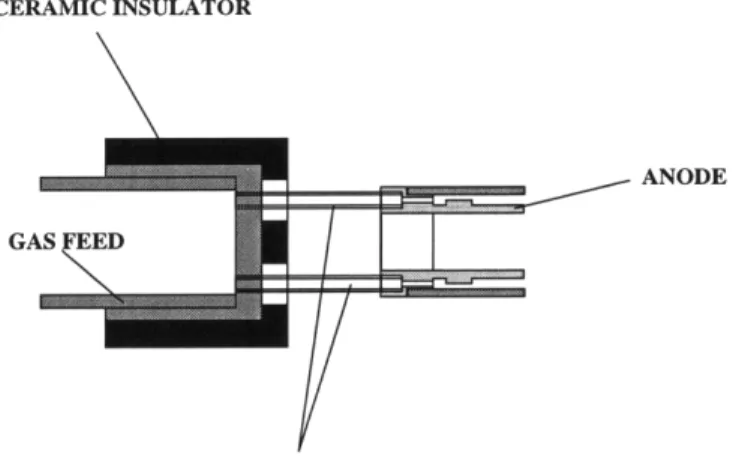
which of the two predominates. The heat deposition rate per unit area scales as power/area - 1/L. The radiative cooling rate per unit area is e(T)cT 4, independent of scale, and so, if radiation dominates, the wall temperature would increase roughly as 1/L (a significant problem for small L, as contemplated here). The conductive cooling rate per unit area is kAT/1, where 1 is some thickness, and so this cooling rate scales as 1/L, the same as the deposition rate; so, if conduction is dominant, wall temperatures can be kept invariant upon scaling. Therefore high temperatures within the channel and at the anode can be avoided by designing adequate heat con-duction paths from the channel out to the surroundings. Since the anode is kept at a positive potential with respect to ground, it is virtually impossible to maintain direct contact of the anode with an external heat sink. Instead, the anode, along with its electrical leads can be designed as a dual-purpose device. The propellant feed lines that normally supply gas to the anode can be used to conduct heat generated inside the channel towards the back of the thruster. Using for the back support structure a material which is a good electrical insulator as well as a good thermal conductor, the heat can be transferred to the surrounding metal, maintained near ambient tem-perature. From the materials perspective, a heat-conducting ceramic such as BN or A1N would be most appropriate. Although AIN has a higher thermal conductivity, it is harder to machine, hence BN was selected. The anode-body insulation assembly is schematically shown in Fig. 3-6.
CERAMIC INSULATOR
ANODE
GASED
CAPILLARIES
Figure 3-6: Anode insulation assembly
3.3.1
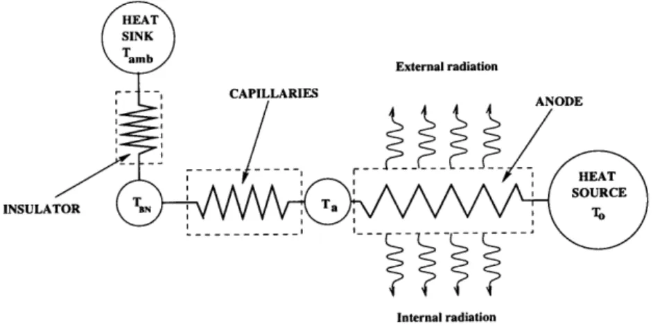
Analytical Thermal Model of the Anode
Another important aspect from the materials standpoint is the anode design. A simple one-dimensional thermal model presented below has shown that the anode tip temperatures would not exceed 1300 C'. The analysis was carried out under the assumption that all of the heat generated at the anode is allowed to be either radiated to the magnets or to be conducted through the gas-feed lines to the back of the thruster where it is rejected to the surroundings. Since the heat generated inside the channel arises mainly due to the thruster inefficiency, roughly 25 W of the total power would be dissipated as heat to the walls. Localized heating due to the impinging ions was neglected in this simple model. Assuming a 1D geometry as shown in Fig. 3-7, one can compute the temperature distribution along the anode, given the input power Qin = 25W and the ambient temperature Tamb = 300 K. It is further assumed that all of the heat is generated at the tip of the anode (x = 0) and conducted through the anode and then through the capillaries to the insulating material (BN) where it is rejected to the support structure, kept at the ambient temperature. Along the anode, part of the heat flux is lost due to radiation to the surrounding magnet and to the central pole. These heat fluxes can be accounted for in the balance and the rate of change of the total heat flux along the anode can be
INSULATOR BNF V V V VV" kjIV V V V V
Internal radiation
Figure 3-7: 1D thermal model
written as follows:
dq(x) = -27r(Ro + Ri)waT 4(x)
(3.13) dx
Since the ultimate goal is to obtain a temperature profile, the total heat flux can be related to the anode temperature through the Fourier law:
q(x) = -kaAa dT(x) (3.14) dx
These equations can be solved with proper initial conditions to yield the following differential equation:
dT(x) /47r(Ro + Ri)T Qin (3.15)
dx kA A [T() T5 ] + [ ] (3.15)
where Ro and Ri are the outer and inner radii of the anode respectively, ka is the thermal conductivity of the anode material, Aa is its effective heat conduction area, and Ttip is the anode tip temperature. This equation is incomplete by itself and requires another condition. This condition can be obtained by relating the heat flux at the anode root (qa) to the respective temperature gradients across the capillaries and across the insulator:
(Ta - TBN) a = Rcap(3.16)
(TBN - Tamb) (3.17) RBN
where Rcap and RBN are the effective thermal resistances of the capillaries and the boron nitride (BN) insulator respectively. The last three equations can be solved iteratively to obtain the anode temperature distribution and the corresponding ra-diative heat fluxes to the central post and the outer magnetic shell. With the proper choice of material properties as well as the assembly geometry it is possible to achieve reasonable tip temperatures yielding an adequate safety margin. Quantitative results if the simulation are presented in the next section.
3.3.2
Material Selection
The analysis based on the above model has shown that conduction through the feed lines is a dominant process in the heat rejection mechanism. In addition, because of the large contact area at the back, the temperature of the magnet surrounding the anode remains close to ambient. Therefore, the material of choice for both the anode and the feed lines needs to have the following characteristics:
* High thermal conductivity to ensure adequate heat rejection rate through
con-duction
* High surface emissivity to enhance heat rejection by radiation
* Adequate melting point (Tm > 1700 Co), compatible with the limiting values pre-dicted by the model
* Easily machinable
Although refractory materials, such as W, Ta, or Mo, seem to best fit this category, the intricate shapes at such small dimensions are extremely hard to manufacture out of pure metals. Alloys of these refractories with copper, nickel, or iron, although more ductile, have melting temperatures that are below the acceptable limits and therefore would not be appropriate for this application. Finally, the preference was given to platinum, as it is an excellent heat conductor, has a high (but perhaps marginal)
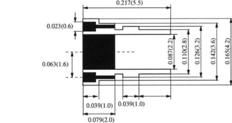
0.217(5.5)
0.023(0.6)
0.063(1.6) 0.039(1.0) 0.039(1.0) 0.079(2.0)
Figure 3-8: Anode configuration
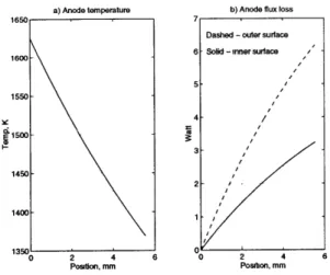
melting point (Tm = 1700 Co), and it is easily machinable to the required tolerances. Low margin resulting from high operating temperatures requires further investigation in this direction to search for a more suitable material, thermal design, or manufac-turing techniques to be used for this application. The anode configuration chosen for the final design is schematically shown in Fig. 3-8. It consists of two parts which are machined separately, and mounted together by means of a press fit. A small flow buffer in the middle of the channel is made in order to redistribute the flow delivered by the four capillaries uniformly around the circumference. The capillary tubes for propellant injection were made out of platinum as well and pressed into the anode. Platinum was chosen for each of these components in order to match thermal expan-sion coefficients and insure good fit between the parts at elevated temperatures. The anode temperature profile along with the radiative heat fluxes as predicted by the model for the selected geometry are shown in Fig. 3-9
3.4
Cathode Design
Due to the reduced emission currents required to neutralize the ion beam, little atten-tion has been given to the design of a new cathode. Although the new generaatten-tion of microfabricated field-effect (cold) cathodes seems to be promising for this application, no state-of-the-art technology exists at the time for their successful implementation.
a) Anode temperature b) Anode flux loss IT 3-1450 - 2-1400 1 1350 0 0 2 4 6 0 2 4 6 Position, mm Position, mm
Figure 3-9: (a) Anode temperature profile; (b) Radiative heat fluxes
This is mostly due to the high voltages involved, sputtering problems, and current leakage that could result in a reduction of the overall efficiency. Hollow cathodes, con-ventionally employed in the SPTs, do not easily conform to the photographic scaling, yet they do have some potential for being miniaturized for future applications. For preliminary testing it was decided to resort to the standard thoriated tungsten or molybdenum filaments because of their ease in implementation. The main disadvan-tage of the filament is that it consumes a great deal of power (50 W/cm2) because of its high-temperature operation. Materials which have lower work-function such as LaB6 would be more suitable for this application, however, they are somewhat
difficult in handling and operation. For initial testing the filaments (shaped as spi-rals) were dipped into a barium oxide solution and left to dry out under the heat of high-intensity lighting. The coated filament was subsequently installed into a vacuum chamber for further testing. The barium oxide coating lowered the workfunction of the metal considerably and allowed for adequate emission at reduced power levels. The optimal choice of a cathode for this application has not yet been found and the subject needs further investigations.
1mm
Figure 3-10: Final design schematic
3.5
Final Design
The final version of the miniaturized Hall thruster is schematically shown in Fig. 3-10. The frontal cap (made out of stainless steel) is a structural component that presses the magnets and a protective carbon ring together into the iron assembly. The carbon ring is located in front of the main magnet near the opening of the channel (shown dark on the picture). It protects the magnet from the high-velocity ions impinging into the walls as they accelerate away from the anode. The main propellant feed line is brazed into a copper distributor region which then delivers propellant into the four platinum capillaries. The whole anode assembly is fitted and held by a chromated copper disk mounted to the magnetic core in the back. The disk is a structural support which is also used for mounting the thruster to the test rig.
Chapter 4
Operational Testing
4.1
Testing Facility
The miniaturized thruster was tested for operation in a vacuum chamber equipped with a single mechanical and a single diffusion pumps (see Fig. 4-1). The chamber pressure was monitored by means of a Stokes gauge as well as an ionization gauge. The steady-state background pressure without gas flow was measured to be on the order of 5 x 10⁻⁵ torr and 5 x 10⁻⁴ torr with near nominal propellant flow rates. It is known
from the available data that 1.3 kW thrusters have been operated in a chamber at 1 x 10- 5 torr background pressure [3]. Scaling to the smaller dimension yields pressures on the order of 3 x 10⁻⁴ torr. Therefore the minimum achievable background pressure is somewhat marginal. Although this is acceptable for preliminary operational testing, better vacuum would be required for accurate performance evaluation.
Two power supplies were used, a DC type for powering the main discharge chamber and an AC type for preheating the filament. The voltage-current characteristics were monitored at all times by a combination of analog and digital multimeters. The thruster body potential was monitored as well by an insulated probe mounted to the outer surface. This was done in order to detect and correct possible shorting between the anode and the body due to the poor tolerances of the anode mounts.
The propellant was injected into the chamber via a small 5 liter tank which was used for calibration purposes. The gas was throttled through a variable-size orifice
THRUSTER CATHODE
POWER
-ANODE VOLTAGE GAS
Figure 4-1: Testing facility
(valve) while the pressure drop in the tank was monitored to determine the flow rate. The upstream pressure inside the calibration tank was monitored by a sensitive digital pressure transducer as well as an analog gauge to measure large scale pressure variations.
No thrust measurements were performed at this time as these measurements re-quire a sensitive microbalance. Procurement of such a balance in the future will allow quantitative assessment of thruster performance as well as validation of the scaling laws as applied to the miniature device.
4.2
Experimental Results and Evaluation
The thruster has been tested with Argon at various operating conditions. Voltage vs. currect characteristics were recorded for different mass flow rates. The results are presented below in Fig. 4-2.
Although the thruster performance can not be properly evaluated based solely on this information, some qualitative data can be extracted in order to make a compar-ison with the existing argon-fed thrusters. In order to make a fair comparcompar-ison, it is necessary to estimate the ratio IbIa of the beam to anode currents, from which one can determine utilization efficiency as well as the I, based on the voltage-current characteristics for different flow rates. This can be done by assuming an acceleration
0.7 0.6 0.5 0.4 0.3 0.2 0.1 S""~ Flowratf=O.:mg.sefc * I Flow raec-34mgIaeq Flow rat~P=21mg/eed i"Flow rae0. -3mg/ee
V -// 7 i . : ..: 0 1 %o 100 120 140 160 18o 2 Voltage, V
Figure 4-2: I-V characteristics
efficiency:
(4.1)
- a
I,
where I is the beam current and Ia is the measured anode current. The utilization efficiency can then be computed:
Ibmi
=7 rhe (4.2)
Specific impulse can then be estimated from the ion jet velocity and r7: C17u
Sp - (4.3)
where c = 2eV/mrn is the ion jet velocity. The thrust can be computed from the specific impulse and the measured mass flow rate:
F = rhgI, (4.4)
and the overall efficiency:
F2
r - a = 77,a (4.5)
2rhVIa
The comparison was made to the data for an argon-operated Hall thruster published in a paper by K.Komurasaki (Tokyo, Japan) [1]. The data presented there is for a 48 mm thruster operating at relatively low flow rates (- 0.6 - 1 mg/sec). The
0.1 0.09-- . o 0.08 -0.07 0.06 -0.05 . . 0.04-0.03
-C EXp.dta mass flow 1.9 mg/seec
0.02 - .i.. 1mg.sec 0 Komirasaki 0.833mg/sec 0.01 0 KomQrasakd 0.625mg/sec 100 200 300 400 500 600 700 800 900 1000 Isp, Sec
Figure 4-3: Thruster Efficiency vs. Specific Impulse
accelerator efficiency for the miniaturized thruster can be determined by scaling up the flow rate from 0.2 mg/sec corresponding to our 3.7 mm thruster to 1.69 mg/sec corresponding to the 48 mm device described in the paper. It is observed from Komurasaki's data that the acceleration efficiency does not change much for a given mass flow rate, although it does depend on the flow rate. Hence, since our flow rate is somewhat higher than the one used in Komurasaki's tests, the acceleration efficiency can be extrapolated to the flow rate of 1.69 mg/sec. This would place the operating conditions of the miniaturized Hall thruster on the same map as the device presented in the paper. Due to the highly non-linear dependence of the efficiency with the flow rate, extrapolation was done for a single I-V characteristic closest in flow rate to the experimental data. The acceleration efficiency was linearly extrapolated and was estimated to be about 0.43 for the mass flow rate of 1.69 mg/sec. Using this efficiency as a baseline, the thrust, the specific impulse, and the overall thruster efficiency were computed for the I-V characteristic corresponding to rh = 1.69 mg/sec (upscaled from 0.13 mg/sec of true mass flow rate). The dependence of the overall efficiency on the specific impulse for the miniaturized thruster as well as Komurasaki's data are presented graphically in Fig.4-3
In order to show the comparison between the two engines the total efficiency versus mass flow rate for a particular value of the specific impulse can be extracted from Fig. 4-3. These data are graphically depicted in Fig. 4-4. The right-most points on each of the three curves correspond to the operating conditions of the miniaturized thruster
0.1 0.09 - p.00 se aW... m lap=400 sec 0.08 - I p=50sec jsp=500 sec 0.07 w 0.05 -Usp=300 sec 0.04 0.03 .. .. ... 0.02 0.0 .6 0.8 1 1.2 1.4 1.6 1.8 Flow rate, mg/sec
Figure 4-4: Thruster efficiency vs. flow rate
while all the other points correspond to Komurasaki's thruster conditions. Although this analysis is by no means conclusive, the linear dependence in Fig.4-4 indicates an excellent match between the operating conditions of the two devices. The low efficiencies at these operating conditions are due to the higher ionization potential of Argon in comparison with Xenon. Even though the efficiencies can be driven higher by operating at higher I,,, the low molecular weight of Argon in comparison to Xenon yields higher currents for a given voltage. This would result in larger power dissipation and possible damage to the anode or the magnets. For that reason, the thruster was run at such currents as to operate within the limits of the nominal power specification (50 W), hence resulting in lower efficiencies.
4.3
Conclusions
The effort to miniaturize the Hall thruster had proven to be a success despite of the number of difficulties encountered at the design stage and in the manufacturing process. It is also evident from the comparison to the larger model of the Hall thruster that it is possible to reproduce the same or similar efficiencies at small scale. Further testing is required to quantitatively evaluate the thruster performance. Procurement of a sensitive thrust balance in the future will allow to make precise thrust measurements and to make conclusions as to whether thruster's performance is adequate at such small scale. Thermal design, although marginal in this case,
can be improved by using refractory materials for manufacturing of the anode as well as propellant capillaries. It is also important to ensure good thermal contact between the anode and the capillaries to conduct as much heat as possible out to the surroundings. This can be done by designing a monolithic anode which eliminates thermal mismatches, ensures good contact, and improves position tolerances between the anode and the magnets.
Although the use of permanent magnets for this design has proven to be successful, little further reduction in size of the thruster is possible as smaller devices would require yet larger confining fields. This is due to the limitations in the strength of the state-of-the-art magnetic alloys. If yet smaller devices are needed, some of the performance characteristics may need to be sacrificed to maintain adequate electron confinement.
It is not possible at this stage to make any definitive conclusions as to the va-lidity of the scaling laws. However, it is evident from the comparison to the larger Hall thruster model that the qualitative behavior matches experimental observations. Further analysis and precise thrust measurements will allow us to validate the scaling theory and evaluate the microthruster performance.
Although the issue of reduced lifetime has not been given much attention, it de-serves special consideration in any future work on micropropulsion. Drastic reduction in the lifetime, as predicted by the scaling laws, has not been experimentally verified and needs further justification. Furthermore, no lifetime data is currently available on the large TAL thrusters. It is expected, however, that TALs will prove superior to SPT thrusters in terms of their lifetime. This is due to the thinner and favor-ably repositioned ionization zone. In addition, the plasma region in TALs is pushed further out of the channel, thus possibly reducing erosion and improving lifetime in comparison to a similarly sized SPT. Hence, no conclusions can be made at this time as to whether or not the lifetime of a microthruster is adequate for a specific mission.
Bibliography
[1] K. Komurasaki M. Hirakawa Y. Arakawa. Plasma Acceleration Process in a Hall-current Thruster. 1993.
[2 J.R. Brophy J.W. Barnett J.M. Sankovic D.A. Barnhart. Performance of the Stationary Plasma Thruster: SPT-100. 1992.
[3]1 J.M. Sankovic J.A. Hamley Haag. Performance evaluation of the russian SPT-100 thrusters at NASA Lewis. 1993.
[4] A.P. London. A systems study of propulsion technologies for orbit and attitude control of microspacecraft. 1996.
[5] M. Martinez-Sanchez. Scaling of Hall Thrusters. 1995. [6] V. Khayms M. Martinez-Sanchez.
Microsatellites. 1996.