Design and Control of a Reconfigurable Bed/Chair System
with Body Pressure Sensing
by
Joseph S. Spano
B.S.M.E., University of California, Davis, 1995
Submitted to the Department of Mechanical Engineering in Partial Fulfillment of the Requirements for the Degree of
MASTER OF SCIENCE IN MECHANICAL ENGINEERING
at the
MASSACHUSETTS INSTITUTE OF TECHNOLOGY
February 1997
Copyright, Massachusetts Institute of Technology, 1997 All rights reserved
Signature of Author
Depaw ent of Mechania 1l Engineering
January 17, 1997
,,1
Certified by
Haruhiko H. Asada Ford Professor of Mechanical Engineering Thesis Supervisor
Accepted by
Ain A. Sonin Chairmahn, Department Committee on Graduate Students
Design and Control of a Reconfigurable Bed/Chair System with Body Pressure Sensing
Joseph S. Spano
Submitted to the Department of Mechanical Engineering on January 17, 1997, in partial
fulfillment of the requirements for the degree of Master of Science in Mechanical Engineering
Abstract
A reconfigurable chair/bed system has been developed to supplant manual labor associated with the transfer of bedridden patients from the bed to a wheelchair, and allow for postural freedom within the chair to more comfortably execute household routines. In addition, a particular reconfiguration scenario has been chosen and executed to demonstrate machine understanding of human postural preference and successful adjustment of control parameters to match that preference.
The design of a five degree of freedom reconfigurable chair/bed allows for a wide range of control possibilities over patient posture and support. The initial objective chosen for study is the control of the back leaf of the chair/bed to control position of the human trunk. Specifically, for a given posture the preferred human state is one that requires a minimum amount of muscle exertion to maintain this state. A method for measuring human exertion by external sensors and a control method to reduce this exertion is presented.
Interpretive control has been proposed as a control methodology that introduces a floating reference point that moves to relieve muscle exertion as the human changes position. An interpretation element has been included as a high level controller that takes in the raw force data and processes it to generate specific control commands that adjust the static reference point of the backleaf of the chair while actively controlling the dynamic behavior. Issues concerning the stability of this control algorithm are studied. In addition a study of how altering parameters will affect human comfort in the chair are studied by examining response characteristics.
Thesis Supervisor: Haruhiko H. Asada
Contents
Abstract 2
Contents 3
List of Figures 6
1 Introduction 8
1.1 Problem Statem ent... 8
1.2 General System Goals and Requirements... 9
1.3 O bjectives of Thesis ... 11
2 Physical System Concept Development 13 2.1 Functional Specifications. ... 13
2.2 Assessment of Current Technology... 13
2.3 Rail System Design Concept... 14
2.4 Wheelchair/Bed Concept... 16
3 Detailed Design of Five Degree of Freedom Reconfigurable Bed/Chair 23 System 3.1 Kinematics and Workspace... 23
3.2 A ctuator A ssem blies. ... 26
3.3 Horizontal Compensation and Load Cells... 26
3.4 Perform ance Specifications... ... 27
3.5 Platform D im ensions... 27
3.6 Retractable Arm, Neck, and Foot Rests... 27 4 Detailed Mechanism Design of One Degree of Freedom Coordinated 29 Chair/Bed
5 Interpretive Control of a Human-Centered Manipulator 33
5.1 Introduction and Related Work... 33
5.2 Formulation of Task Objective and Performance Index... 35
5.2.1 Problem Statement... 36
5.2.2 Human Signal Identification and Measurement... 37
5.2.3 Specification of Performance Index... 38
5.3 Specification of Controller Archetecture... 39
5.4 Model Formulation and Assumptions... 41
5.5 Gravity Load Estimation and Compensation... ... 44
5.5.1 Gravity Compensation of Contact Force Measurement... 45
5.5.2 Forgetting Factor Design Criteria... 47
5.5.3 Gravity and Friction Compensation in Servo Loop... 47
5.5.4 Resulting Linearized System... 49
5.6 Human Model Assumption and System Stability Criteria... 50
5.6.1 Reduction of Machine Servo Loop... ... 50
5.6.2 Human Model Formulation and Assumptions... 51
5.6.3 Derivation of Closed-Loop Stability Criteria... 51
5.7 Design Methodology for Interpretive Controller... 54
5.7.1 Evaluation of Human Transfer Function Parameters... 54
5.7.2 Determining Interpretive Filter Parameter... 54
5.7.3 Criteria for Specifying Loop Gain... 57
5.7.4 D esign Exam ple... 57
6.1 Solution of Elderly Transfer Problem by Design... 62
6.2 Sensor Interpretation and Control Design to Adapt to Human Preference... 62
6.3 Future W ork... 62
6.3.1 On-Line Tuning of Controller Parameters... 63
6.3.2 Human Instrumentation as Feedback Signal Source... 64
6.3.3 Hidden Markov Model as Estimator and Interpreter... 65
6.3.4 Exploration of Coordinated Multi-DOF Servoing... 65
6.3.5 New Applications for Interpretive Control Methodology... 66
List of Fit
2.3.1 2.3.2 2.4.1 2.4.2 2.4.3 2.4.4 2.4.5 2.4.6 2.4.7 3.1.1 3.1.2 3.1.3 4.1 4.2 4.3 4.4 5.1.1 5.2.1.1 5.2.2.1 5.3.1 5.3.2 5.3.3. 5.4.1 5.5.1Closed Chain, Hybrid 8/4 Bar Linkage... ...
Open Chain, Center M ount ... Schematic of Hybrid Bed/Chair System in Lying Position... Schematic of Hybrid Bed/Chair System in Seated Position...
Schematic of Hybrid Bed/Chair System in Transit... ...
Foam Model of System in Lying Position... ...
Foam Model of System While Reconfiguring... ...
Foam Model of System in Seated Position... ...
Reconfigurable Bed/Chair System Structure... ...
5-DOF Robot in Lying Position... 5-DOF Robot in Seated Position with Person Seated... Detailed View of 5-bar Kinematic Linkage and Actuator System...
1-DOF Bed/Chair in Lying Position...
1-DOF Bed/Chair in Seated Configuration... ...
CAD Drawing of Side View of the 1-DOF Bed/Chair... CAD Drawing of Top View of the 1-DOF Bed/Chair... Block Diagram of a Human-Centered Manipulator... Powered Chair Backleaf for Physical Assistance... Human Muscles as Tandem Drive Unit and Load Cells... Controller Transfer Function ... M echanical A nalog... Schematic of Controller in System . ... Schematic Model of Bed/Chair System... Block Diagram of Bed/Chair System...
ures
15 15 16 17 17 18 18 19 20 24 24 25 29 30 31 32 34 36 37 40 40 41 43 455.5.4.1 Resulting Linearized Bed/Chair System... ... 50
5.6.3.1 Simplified System Block Diagram... 52
5.7.2.1 Simple Bode Plot Illustrating Design Specifications... 56
5.7.4.1 Experimental 5-DOF Reconfigurable Bed/Chair... 58
5.7.4.2 Instrumented Backleaf of Bed/Chair ... 59
5.7.4.3 Simulated Frequency Response Plots... 60
Chapter 1
Introduction
1.1 Problem Statement
The rapid increase in the elderly population worldwide is a critical problem faced by today's society. Effective technologies for elder care are badly needed to relieve costly, manual, labor intensive care strategies employed in hospitals and nursing homes
today. A home-based health care system that incorporates physical assistance by
intelligent machines offers a promising and realizable solution to the growing challenge ahead.
To realize the use of intelligent machines as servants in the home environment to people in need of assistance, many questions concerning the relationship among design, control, and the human being served must be answered. Clearly, a vulnerable human relying on a machine for support in the home environment requires a level of human-machine symbiosis that has yet to be realized. It is no longer possible for the human to understand and adapt to the machine to ensure a successful relationship. On the contrary, in this situation the machine must understand the human. Beyond understanding, the
machine must also be capable of adapting to human prefere9ces to achieve the most
comfortable relationship possible.
For this concept to become reality, machine design, control, sensing, and understanding of human preference must all be coordinated to achieve success in a variety of physical assistance scenarios. First, systems must be designed to be flexible and capable of providing assistance in a variety of home scenarios. In addition control system design
must be focused on identifying and realizing the physical arrangement and level of assistance most preferred by the human. Among the most critical research issues is how to extract the preference of the human in a non-invasive manner that yields consistent, accurate results. Specifically, an appropriate interpretation scheme must be conceived that can directly translate measured data to specific control objectives that can be carried out by a more traditional machine control routine. These control objectives must agree with the physiological preference of the human and all control parameters that affect the physical human-machine interface must be tuned to achieve this goal.
1.2 General System Goals and Requirements
To begin to understand more specifically what daily activities of the elderly offer the greatest opportunity for implementation of physical assistance, site visits to various elderly care facilities were made. Many useful pieces of information were revealed in those visits. For instance, more than 80 percent of the elderly residing in nursing homes or hospitals decided to do so primarily because they could no longer be treated at home after having been left permanently bedridden. This illustrates that many elderly patients are capable of living at home comfortably with the exception that they have mobility difficulties. Related activities include physically interacting with the commode. By wide consensus among the elderly, care practitioners and advisors in its most general form the first machine prototype should be able to offer physical assistance in the following areas: * Bed/Chair Transfer
* Bedsore Prevention * Commode Difficulties
* Standing from Sitting Position
In addition to the functional goals, general system requirements that address the user's perspective are required. These requirements can be placed into two categories: * Patient Safety
* Patient Comfort
The system must provide freedom to the patient in a manner that keeps the patient
comfortable and safe at all times. This implies an understanding of each patient's
definition of comfort and successful translation of this understanding to the design and control of our system. It is in this area that new research developments are needed. Design of the mechanisms, sensors, and controls must be approached as one integrated system to achieve patient safety and comfort. Safety is the first high-level control priority, but after satisfying all safety considerations, a successful control strategy must optimize human comfort. The primary safety considerations include monitoring body position and configuration on the chair to ensure that any impending actuation does not pose a threat of physical harm to the human body. For example, if one of the patient's arms were to slip into a position where reconfiguring the chair could cause pinching of the limb, the system must be aware of this fact and halt progress until the condition is rectified. Sensors must be included in the design of the chair surface that can detect pressure normal to the surface and also tangential to the surface. This information can be used to establish a series of safety checks that must be passed before action is taken.
The same sensory information that guarantees patient safety can also be used to interpret patient comfort. If skin shear or pressure becomes too high at some particular configuration it can be reasoned that this configuration is unacceptable and should be
avoided if possible. For example, while transitioning from a seated to standing position, the multi-DOF chair system offers a wide range of possible trajectories to achieve that goal. By measuring the skin shear and pressure patterns for any number of trajectories, the trajectory can be chosen that minimizes skin pressures, thus providing maximum comfort.
It is evident that machine design, sensor design, and controller design must all be integrated to achieve the functional and system goals agreed upon for success in the home-health care arena.
1.3 Objectives of Thesis
This thesis describes a new technology for home-based elderly care focusing on mobility assistance for bedridden persons. This new system illustrates the design of a machine, sensors, and controller that offers a specific service to the human in a safe and comfortable manner. A reconfigurable chair/bed system has been developed to supplant manual labor associated with the transfer of bedridden patients from the bed to a wheelchair, and allow for postural freedom within the chair to more comfortably execute household routines. This thesis details the concept formulation and detailed design of a reconfigurable bed/chair that solves the bed/chair transfer problem and gives a wide variety of position and support options to improve patient comfort. In addition this thesis details a new implicit human-machine communication scheme that includes a digital interpreter and active sensing to infer human desire to change configuration by motion augmentation. A method for tuning control parameters is presented that illustrates how adjustments in the characteristics of the controller affects human interaction with the chair. Parameters are chosen that allow the human to interact and communicate with the chair
with the least amount of muscle exertion and the most comfort within the stability limits of the aggregate human-machine system.
The design of the five degree of freedom reconfigurable chair/bed allows for a wide range of control possibilities over patient posture and support. The initial, specific control objective that has been chosen for study is the admittance control of the back leaf of the chair/bed to control position and stiffness of support of the human trunk. Specifically, for a given posture the human should have to exert a minimum amount of muscle force to maintain this state. Measurement of the level of human muscle exertion becomes a critical challenge. In this thesis, a method for measuring human exertion by external sensors and a method of control to reduce this exertion is presented.
Chapter 2
Physical System Concept Development
2.1 Functional Specifications
To begin to make an effective evaluation of human comfort with respect to those parameters that can be affected by the bed/chair system the system must be able to conform to all reasonable body configurations, generate a wide range of coordinated motions and speeds, and maintain physical stability. These criteria establish the necessary functionality of the mechanism to be designed.
To achieve the system requirements of patient safety and comfort, sensory information indicative of these qualities must be provided. The machine must be instrumented to measure physical quantities that when incorporated into the system controller can provide the necessary indication of patient safety and comfort. Of course the system controller design must be carefully considered to have the ability to properly interpret sensor information and generate the appropriate control action.
2.2 Assessment of Current Technology
Currently mobility assistance for the elderly is addressed using manual manipulation of the patient by care practitioners. Transferring the bedridden from a bed to a wheelchair is an extremely laborious, physical job, which, for average people without the use of special equipment, is difficult to perform. A variety of equipment for lifting the bedridden has been developed and deployed at both hospitals and homes. In some cases manually controlled mechanical devices are utilized. These include a host of mechanical lifts or hoists that use a harness to grasp the patient and a manually operated hydraulic
system to provide the manipulation effort. Other types of transport equipment include sliding chairs and belt-conveyer beds. The transfer board is another method utilized in care facilities that involves no active mechanical manipulation. These systems are not well received by elderly patients. They suspend the patient, making them feel out of control and unsupported. In addition in many cases they apply high pressure at specific points that causes bruising and in more dramatic cases, breaking of bones at the point of contact.
Clearly the methods of physical assistance for the elderly in care facilities and in the home are based heavily on direct assistance from several care practitioners with the possible aid of a simple manually operated mechanical device with a single functionality. There are no devices in existence that utilize automation or active sensing. In addition there are no mechanisms that offer multiple functionality from an integrated system. With this in mind there is no precedence for our work, only a set of problems that we would like to solve using an integrated system design approach.
2.3 Rail System Design Concept
Two versions of a rails system design concept are illustrated in Figures 2.3.1 and
2.3.2. These two figures illustrate different kinematic structures with the same physical
assistance functionality. This system utilizes a mobile chair suspended from the ceiling. Many degrees of freedom are included, but require a track system to be included in the house to allow the human to move about freely. The suspended chair integrates into the bed to provide a no-transfer transition from bed to chair. The elaborate track system required to make this concept feasible is a major deterrent to further development.
Figure 2.3.1 Closed Chain, Hybrid 8/4 Bar Linkage
2.4 Wheelchair/Bed Concept
The need for transferring the patient between the bed and the wheelchair is eliminated by devising a hybrid wheelchair/bed system that serves both as a wheelchair and as a bed. When used as a wheelchair, the patient can take various sitting positions and
move around freely within a house. When used as a bed, the patient can lie flat in a
commodious space. The transition between the two modes, wheelchair and bed, can be performed easily and quickly without laborious operations. The reconfigurable chair/bed concept supplants human exertion with mechanical actuation and intelligent control. The approach is a unified solution to these problems created by taking a system level perspective of the desired functions. Figures 2.4.1, 2.4.2, and 2.4.3 show schematics of a hybrid wheelchair/bed system consisting of a reconfigurable chair and a U-shaped bed. The reconfigurable chair can move from a lying position to a seated configuration in one smooth motion back actuating the appropriate leaves of the chair.
Figure 2.4.2 Schematic of Hybrid Bed/Chair System in Seated Position
Figure 2.4.3 Schematic of Hybrid Bed/Chair System in Transit
The wheelchair can be detached from the bed for the transport of the bedridden person, and docked to the bed for sleep. The transition can be made while the patient is lyipg in the bed. The chair is reconfigurable so that it can be a flat bed or a couch with a reclining back with a foot rest. The wheelchair is narrow enough to maneuver freely within a crowded room, while the bed is wide enough to prevent the patient from falling out and roomy enough to provide comfort.
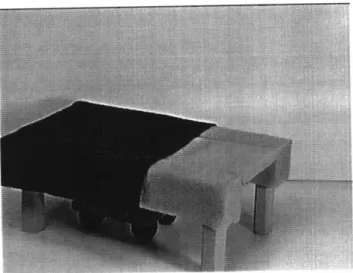
Figure 2.4.4 Foam Model of System in Lying Position
Figure 2.4.6 Foam Model of System in Seated Position
Figure 2.4.4 shows the wheelchair/bed system in the docked bed configuration. To detach the wheelchair from the bed portion, the back of the chair is first raised
half-way through the position shown in Figure 2.4.5; then the whole body of the chair is slid
off from the end of the bed portion and the foot rest is folded down, as shown in Figure 2.4.6. Finally, collapsible arm rests are raised (not shown in figure). To move the chair back to the bed configuration, the procedure is simply reversed.
The reconfigurable bed/chair system is comprised of three major elements: the human being, the actuated mechanism, and an extensive array of sensors. The objective is to fully understand the detailed relationship among these elements to clearly define for a particular system, what states are observable, what control objectives are achievable, and how to optimally reach these goals. Specifically we want to realize the full potential of the unique sensing and actuation ability of the reconfigurable bed/chair system to promote elderly patient safety, health, and enhancement.
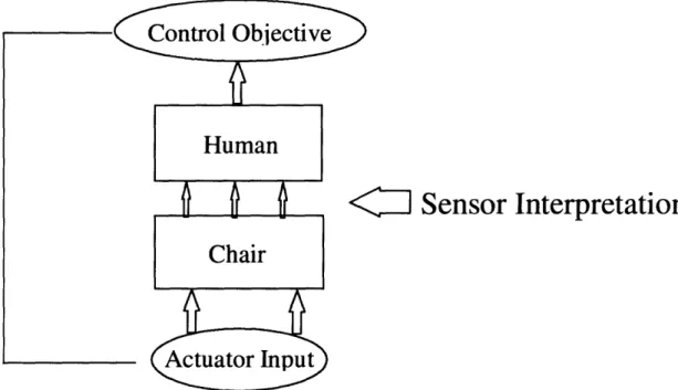
The closed loop control of the reconfigurable bed/chair system is an example of the intimate cooperation that must exist among the three elements to reach the desired objective (Figure 2.4.7).
1] Sensor Interpretation
Figure 2.4.7 -Reconfigurable Bed/Chair System Structure
Dynamic models of the bed/chair mechanical system can be formulated that can be utilized
to tailor machine performance to desired specifications. However, our desire is to
monitor, and at times control the status of the patient. With this in mind a clear
understanding of the causal relationship between the machine and human is necessary. Because the human is not rigidly linked to the mechanical system, a one to one relationship between bed/chair configuration and human body configuration does not exist. To resolve this issue pressure sensor data extracted from an array of sensors mounted to the chair/bed pad surface must be processed to yield a good estimate of the relationship
between the human and the bed/chair. With this estimate, a simplified human model
processed by the controller to establish new system inputs that will move the system toward convergence about the performance objective. This is illustrated in Figure 2.4.7.
Active posture control is an example of one possible function made possible by this human-machine-sensor integration strategy. For example the chair frame can be reconfigured to move a patient through sitting, lying, reclining, and standing positions. Also these same actuation abilities allow for a certain amount of local posture control. In addition the frame can be servoed to apply a specific impedance to human motion. Control over this impedance has applications in patient exercise for maintenance and rehabilitation of joint and muscle strength and range of motion. All of these diverse control objectives are possible with adjustments in controlled parameters of our highly flexible, integrated human-machine-sensor system, not modifications of mechanisms. Previous work has emphasized pressure measurement and equilibrating pressures. [Brienza, 1996]
Sensor data is a key feature of the bed/chair system. This data can be processed to estimate a number of human activities and physiological status for both patient monitoring and machine control applications. Some examples are listed:
* Respiration rate can be deduced from low frequency oscillations in the pressure detected in the human trunk region.
* Frequency of body position reconfigurations on the chair/bed surface can be used as an indicator of the comfort of the patient during sleeping or waking hours.
* Particular body configurations can be detected that indicate postures that could place the patient in danger of injury.
* Classification of posture patterns over time can lead to insight into personal habits that may indicate health problems.
* Pressure sensor data can be used to provide feedback for impedance control of the bed/chair system for exercise and rehabilitation with nominal trajectory and impedance tuned to a specific human.
The 5-DOF bed/chair system offers a wide range of body trajectories to achieve a desired body position. Depending on the patient, different body positions and motion
trajectories will correspond to a varying degrees of comfort for each individual. In
addition the chair offers a diverse array of sensory data that can be tapped to interpret the level of human comfort and monitor patient status. A challenging aspect of this work is the use of this data to indicate human satisfaction with chair performance in a given physical assistance scenario and how this data can be used to suggest changes in system behavior that will offer the human a higher level of comfort.
Chapter 3
Detailed Design of Five Degree of Freedom Reconfigurable Bed/Chair
System
3.1 Kinematics and Workspace
To achieve the desired functionality described in the previous section a 5-DOF
robotic chair has been designed. The chair features independent vertical and rotational degrees of freedom of the chair seat. In addition the back support and leg support leaf are independently actuated. The chair also features arm, leg, and neckrests to increase the comfort and support of the patient. The entire chair can be moved fore and aft by a fifth independent degree of freedom that is actively controlled to maintain balance over the vehicle platform upon which it will be mounted.
All together the chair is capable of assuming an infinite number of configurations
ranging from standing up with a seat angle of 600 (Figure 3.1.3) from horizontal to a reclined seat position of 300. The seat can move vertically 6" to adjust to various bed levels (Figure 3.1.1). Together the independent degrees of freedom can be coordinated to
achieve among others, a reclined, seated, standing, and lying positions. The lying
configuration is shown in Figure 3.1.1. The seated position is shown in Figure 3.1.2. The standing position is shown in Figure 3.1.3. Independence of the vertical and rotational degrees of freedom is achieved by a very compact five-bar kinematic linkage shown in Figure 3.1.3.
Figure 3.1.1 5-DOF Robot in Lying Position, Head and Neck Rests Retracted and Armrests Extended
Figure 3.1.3 ,Detailed View of 5-Bar Kinematic Linkage and Actuation System When designing the five bar linkage one must be aware of toggle positions particularly when working with a workspace as broad as that offered by the chair in such a compact
mechanism. If a toggle position is reached the kinematic relationship becomes
discontinuous and smooth control is not possible. Avoiding toggle positions was a top priority in the design of the kinematic structure of the chair/bed mechanism.
3.2 Actuator Assemblies
The seat vertical and rotational degrees of freedom are actuated by ball screw assemblies powered by DC servo motors. In addition the back and leg support sections of the chair are also independently actuated. These rotational joints are driven by DC servo motors via worm gear transmission. Both of these actuation assemblies are shown in Figure 3.1.3. The back and leg rests are actuated independent of the seat. DC Servo motors via a specifically designed spur gear and worm gear transmission arrangement
provide power to move these joints. Prismatic actuators are utilized to reduce the
extremely high torque loads that would be required to actuate the linkage by rotational actuators at the pin joints. These prismatic actuators are actuated by ball screw assembles driven by DC servo motors placed in parallel in a custom arrangement to conserve space.
3.3 Horizontal Compensation and Load Cells
To maintain physical system stability while maintaining as small a footprint as possible, the entire chair assembly has been placed over a custom designed horizontal linear slide that compensates to place the center of gravity of the chair and patient over the
geometric center of the holonomic, omnidirectional vehicle. 12" of horizontal
compensation has been designed into this system. A view of the load cells and linear slide is shown in Figure 3.1.3. The horizontal degree of freedom is used to maintain balance of the chair structure and the human over the holonomic, omnidirectional platform in one dimension. Utilizing data collected from four load cells fixed to the bottom corners of the chair the horizontal actuator is controlled to align the center of gravity of the load over the
top of the geometric center of the holonomic, omnidirectional platform. In addition, in emergency scenarios, load cell data can also be utilized to predict an impending sideways
tip-over condition and the holonomic, omnidirectional vehicle can be directed to
compensate and resolve the condition.
3.4 Performance Specifications
Maximum actuator velocities are 1"/sec for linear actuators and 3 rpm for back and leg support sections. The system was also designed to carry the load of a 2001b patient. Appropriate gearing, transmission, and motor choices were made to handle the torque loads induced by the 2001b load. All actuation assemblies are constrained to handle the loads without excessive deformation of the structure of the robot while maintaining adequate gear engagement for the worm gears.
3.5 Platform Dimensions
The chair/bed dimensions were designed in accordance with established seat dimension values found in human factors literature. In addition the width of the bed/chair system has been specified at 22 inches to give plenty of room on the chair for the patient, but still allowing the chair to move freely through standard doorways in the home.
3.6 Retractable Arm, Neck, and Foot Rests
In the interest of safety the chair/bed was designed with manually actuated armrests, footrest, and neck rest shown in Figure 3.1.1. These were designed into the chair frame after consultation with medical professionals. It was advised that in order to maintain patient safety, these safeguards must be included in the design to keep appendages of the patient from colliding with the environment while the chair is static or
moving. Appropriate mechanical stops, rails, and supports are being included in the design to ensure the safety and comfort of the subject under evaluation.
Chapter 4
Detailed Mechanism Design of One Degree of Freedom Coordinated
Chair/Bed
Two separate bed/chair prototypes have been designed, constructed, and tested at the d'Arbeloff Laboratory for Information Systems and Technology. The first prototype is a five degree of freedom mechanism that offers independent actuation of backrest, leg rest, and seat. The second prototype is a one degree of freedom coordinated prototype that coordinates the actuation of the footrest, neck rest, backrest, and leg rest. The seat remains fixed and the other four joints move in a coordinated manner from a lying flat position to an upright seated position. The seated position is shown in Figure 4.2 and the lying position in figure 4.1.
Figure 4.1 I-DOF Bed/Chair in Lying Position
Figure 4.2 1-DOF Bed/Chair in Seated Configuration
Actuation is achieved by DC servomotors through a planetary gearbox and worm gear transmission. Coordination of the the back support leaf with the front support leaf is achieved by a four bar linkage most easily shown in Figure 4.3. Steel belts traveling through the back and neck support leaf frame tubes coordinate the neck and footrests with the rotation of the back and leg support leaves. Figure 4.4 shows a top view of the 1-DOF bed/chair and the steel belts run inside the 2x2 inch tubes that make up the frame
rails. These belts are invisible to the patient and provide a transmission mechanism that is completely safe. When the chair moves from a lying to a seated position the footrest rotates 90 degrees relative to the leg support leaf to provide feet support for the patient. This 90 degree rotation is provided by a one-one pulley ratio between the seat frame and the footrest drive shaft. When the chair moves from a lying to a seated position the neck rest which is no longer needed is curled behind the back support leaf by a 180 degree rotation relative to the back support leaf. This rotation is provided by a 2:1 pulley ratio between the seat frame and the neckrest drive shaft.
54-3
36.6
--
IGO----w
.1 I~~21A4
2-Figure 4.4 CAD Drawing of Top View of the 1-DOF Bed/Chair
The two chairs have been built to explore the different controllable spaces possible with different actuation abilities. For certain applications one degree of freedom may be sufficient, however other objectives may require the increased controllable space of the five degree of freedom bed/chair. Other objectives may be out of reach of both systems and our research should indicate what actuation ability is necessary to match the controllable space spanned by our control objectives. Additional research efforts can be focused on development of new actuator technologies designed specifically to expand our controllable space. r Il ·- · · HI III [] L/mL _ _ r i ýh L11
Chapter
5
Interpretive Control of a Human-Centered Manipulator
5.1 Introduction and Related Work
The design of the 5-DOF reconfigurable chair provides a mechanical framework capable of solving a variety of physical assistance needs of the elderly, however questions concerning how to exploit the 5-DOF servoing capabilities of the chair to best meet the needs of elderly patients with limited mobility is a critical issue. Specifically, what range of tasks could conceivably be approached, how to best communicate human intention to the chair, and how to best match the chair's servoing capabilities with human preference. Issues of task definition can be clarified by answering the following questions.
* What is the human's desired motion objective?
* Is the manipulator physically capable of meeting this objective? * What set of human signals fully describes his/her control desire? * Can these signals be measured or estimated?
* What closed-loop dynamic behavior of the human-centered manipulator is preferred by the human?
Ans.vering these questions clearly defines the role to be played by the bed/chair system and provides a structure and performance objectives to begin system design for a human-centered manipulator.
Figure 5.1.1 -Block Diagram of a Human-Centered Manipulator
Figure 5.1.1 illustrates the human and the bed/chair system connected by an interpretive controller. A suitable control system must be synthesized to implicitly extract the human desire for robot position and control the chair to best meet those desires. This machine behavior, not only puts the human in the control loop, but puts the human in charge of the chair in a way that he or she is most comfortable. The interface is implicit, the machine reads and interprets human signals that naturally indicate the human desire. This is contrary to typical fixed human-machine interfaces that are rigidly defined by the machine and must be adopted by the human.
Typical human-in-the-loop systems such as master/slave systems look to control some other object and physical feedback comes from artificially generated stimuli. Additional work that involves human-machine interchange of information and power signals to augment human strength in lifting tasks is presented by [Kazerooni, 1993]. The human extender concept of muscle augmentation is analogous, but does not include the human signals as a portion of the closed loop. In the human extender concept the human signals are external inputs into the closed-loop machine system. The human extender
system works in a similar way as our system, but again the object being manipulated is external, not the human him/her self. Current research in the area of control of the chair
surface contour has focused on equalizing pressure on the seat of the chair [Brienza, 1996]. Other foci in the rehabilitation robotics field have been in highly specialized areas such as feeding or lifting [Kawamura, 1995], [Khatchadourian, 1994].
A central research issue of this work is the development of the implicit communication scheme, having the chair actively measure physical quantities, and by proper interpretation, decide on and execute the appropriate system response. In this way the human is not responsible for communicating his/her desire in a manner acceptable to the machine, rather the machine is actively searching for human preference based on natural human tendencies that act as indicators of desired changes to his/her environment. In addition to interpretation of human desire the controller must also adapt itself to provide a system response that satisfies appropriately chosen performance indices. The type of control proposed to resolve this situation is the interpretive control of a human-centered manipulator using an admittance controller.
5.2 Formulation of Task Objective and Performance Index
A human-centered manipulator such as the reconfigurable bed/chair is
characterized by the fact that it interprets human desire and formulates a control action that directs physical effort upon the human exclusively. The unique feature is that the human defines the control input, consciously or subconsciously, and is physically controlled. This implies that the human is present in the control loop and must be considered. Furthermore, performance indices for the system are centered around the
human response because the manipulation of the human is the control objective. The task objective can be clearly defined by answering the questions posed in the introduction.
5.2.1 Problem Statement
A common problem encountered by the elderly is difficulty sitting up in bed. As a
matter of fact 80% of the patients in elderly care facilities are there simply because they were no longer able to arise from bed in the morning and successfully move from the bed to a walker or chair. Typically human assistance is needed to lift and support the elderly in a seated position for feeding or in preparation to move off of the bed. The multi-DOF bed/chair system possesses the actuation ability to move the human from a lying to seated position by servoing of the backleaf, relieving the infirmed patient of the daunting task of pulling oneself from a lying position. See Figure 5.2.1.1.
\I /
p
C)
Figure 5.2.1.1 -Powered Chair Backleaf for Physical Assistance
The task of the chair is to sense abdominal muscle exertion, correctly interpret this exertion as a desire to change position, and move the chair in the appropriate direction to relieve the exertion. In this way the chair interprets the human desire and moves to achieve this goal. We want to augment the human effort required to reconfigure from a seated to lying position by controlling the motion of the backleaf of the chair to reduce to
zero the abdominal muscle exertion of the human at any particular time. The chair amplifying the humans signal can be considered muscle augmentation.
5.2.2 Human Signal Identification and Measurement
Now that we have established a physical assistance need and verified the bed/chair's capability to fill that need we must identify signals generated by the human that indicate a desire to change the position of the backleaf of the chair. A logical way that a human could communicate how he or she would prefer to be seated would be to exert abdominal muscle force and back muscle force in tandem in an attempt to alter chair position and move toward a more desirable state. Figure 5.2.2.1 illustrates the human abdominal and back muscles working as a tandem drive unit. These muscle exertions are the physical signals the human outputs to indicate a desire to move his/her seat position.
Figure 5.2.2.1 -Human Muscles as Tandem Drive Unit and Load Cells to Measure
The next question concerns whether the human muscle signals can be measured or estimated. The evaluation of human preference as determined by the level of muscle exertion can be approached in many ways. Psycho-physical queries can be utilized to get an estimate of human exertion. The validity of these results is questionable and use of this
method in the home setting is impractical. Direct physical measurement of muscle
exertion may be possible, but again, probing the human, possibly in vitro is totally impractical and defeats the ideal of a comfortable, non-invasive human-machine relationship. Instead, if simple, non-invasive physical measurements can be made and the signals processed to estimate the level of human exertion, the machine will have the knowledge necessary to adapt itself to human preference. The contact surface between the human back and the backleaf of the chair is a place where force data can be obtained that contains the human muscle exertion information we seek. In this research load cells were utilized to measure the interaction force between the chair surface and the human. Figure 5.2.2.1 illustrates the use of load cells to measure the contact force between the human body and the backleaf. This type of instrumentation was utilized to be non-invasive, so the patient will be unaffected by the measurement process.
5.2.3 Specification of Performance Index
Our challenge is to establish a control structure that successfully realizes physical
augmentation tuned to each individual's preference. This preference must be
quantitatively defined. The human is most comfortable in this scenario when he or she has to exert a minimum amount of control (muscle effort) to make the chair follow his/her desired position. We define this preference as a minimum energy effort on the part of the
human. If we define Fh as the muscle force exerted by the human we would like the following performance index to be minimized by our control strategy.
J
ooFhl2dt
=
0
F
d
(5-1)
5.3 Specification of Interpretive Controller Architecture
Now that the functionality and performance index for the human-centered manipulator have been clearly defined, a specific architecture for the interpretive controller must be established. It would be desirable to implement a control strategy that requires a minimum amount of muscle exertion to induce chair motion, but allows for spurious changes in muscle force to be filtered by the chair system. Specifically the chair should sense the human's desire to change chair position by reading the muscle signals exerted by the human. The chair should move in a direction that relieves these muscle forces until the human stops exerting which indicates that the desired position has been reached. Given this design criteria, admittance control with an interpretive filter is a logical structure for the interpretive controller because it allows a force to be generated while absorbing spurious force inputs. Figure 5.3.1 illustrates a block diagram of the controller.
Figure 5.3.h--- /( 1 CointS+roller Transfer Function
Figure 5.3.1 - Controller Transfer Function
b
Fh
Figure 5.3.2 -Mechanical Analog
A mechanical analog to the proposed controller is shown in Figure 5.3.2. The
controller acts like a damper that is characterized by the parameter b. As long as there is a human force generated, the reference chair position, theta, moves in the direction of the force. The rate at which the chair position changes for a given force input is governed by
the value of the parameter b. The low-pass filter characterized by parameter, Tint, acts like
a mass element where the force is applied and effectively damps out high frequency oscillations of the human muscle force.
Figure 5.3.3 -Schematic of Controller in System
So effectively, in Figure 5.3.3, the human must exert muscle force for some dedicated period of time before the reference position will begin to change.
5.4 Model Formulation and Assumptions
Figure 5.4.1 illustrates a simplified model of the human-centered manipulator system. The human is modeled as a link element of mass mh resting on the chair/bed structure represented as a separate link of mass mr. The human muscle exerted on the
chair/bed structure is modeled as the externally applied force Fh. The mass centroid of
each link element and the applied muscle force act at specific distances from the rotational joint of the backleaf. Each of these lengths are specified. The chair position theta is specified. Gear reduction and motor constants are included. Of course gravity which plays a strong role in this system is modeled. A list of parameters, their definitions, and estimates of actual values are given:
Parameter Estimate Description
mh 501b=22.68kg Mass of the human
Muscle force exerted by human Chair position
Moment arm of human mass Moment arm of backleaf mass Moment arm of Fh
Gear transmission reduction Voltage applied to motor
.046Nm/Amp Motor torque constant
.084 Volts/rad/sec Back emf constant
.00005865Nms2 Motor inertia
.660 ohms Motor armature resistance
resulting equation of motion for this system is G j KIK2Gr2 GrKI
Gr2 Jm -- + Vo+ mhglhsin0 + mglr
sin0
+ Fhlm + rfR R (5-2) .75m .75m .75m 980:1 Vo K1 K2 Jm R The
g
g
mr
Figure 5.4.1 -Schematic Model of Bed/Chair System
The model has several key assumptions. Due to the slow, quasi-static nature of the motion of the mechanism, dynamic effects of the robot/human system have been ignored, although inertia affects of the motor have been included due to the extremely high gear reduction utilized in this system. Also due to the quasi-static nature of the motion, link flexibility of the chair/bed structure and the human/chair interaction have been ignored and assumed to be rigidly connected. Static friction which is significant in this system with
high gear reduction has been included in the equation of motion. An additional
parameter as the robot structure. This movement of angle reference point from the human hip joint to the bed/chair backleaf rotational joint simplifies the system equations and since mass properties must be estimated anyway this change of reference will not affect the time-varying parameter estimation algorithm.
5.5 Gravity Load Estimation and Compensation
The system equations of motion are nonlinear due to the presence of gravity load as a function of the sine of theta. To begin the detailed design of a controller we would like to linearize these equations by compensating for gravity to cancel its effects in the system equations leaving behind linearized equations of motion that can be dynamically compensated by traditional linear control designs such as a PD controller. Gravity load affects the control of the chair/bed system in another way. The gravity load is a portion of the contact measurement made between the human body and the manipulator. Since we are interested in the human muscle load in this contact measurement we would like to subtract out the contribution of gravity load in this measurement. Estimation of the gravity load is difficult because modeling can give us the functional relationship between the gravity load and chair position, but because our mass parameters and center of mass locations cannot be determined accurately and are time-varying we cannot get exact values for compensation. To solve this problem I employ a recursive least squares parameter estimation algorithm with a forgetting factor to properly estimate and track the time-varying gravity load. These estimates are used to design a gravity compensator for the human muscle force measurement and a gravity and friction compensator for the servo controller illustrated in Figure 5.5.1.
Figure 5.5.1 -Block Diagram of Bed/Chair System
The gravity load is nonlinear and affects both the high and low level feedback loops as
shown in Figure 5.5.1. By gravity compensation we estimate the gravity load and
introduce a static signal that negates its effect leaving a linearized dynamic system in the case of the machine level loop and a pure measurement of muscle exertion at the load cells.
5.5.1 Gravity Compensation of Contact Force Measurement
In our system the gravity load is a function of chair position, human mass
properties and human position on the chair. From our model;
G(O,mh,lh) (5-3)
In the case of contact force measurements the gravity load enters as follows:
G(O,mh, lh) = mhg sin
First we must design the gravity compensation estimator for the contact force measurement. Referring to the system model it is apparent that
Fcontact = Fh + mhg
sine
(5-5)This expression contains the measurable quantities Fcontact and 0 to be used in our
estimation algorithm. Since the human position on the chair is time-varying and the exact mass properties of the human are difficult to measure we will employ the recursive least squares technique for parameter estimation to accurately estimate the unknown mass parameter. In addition we will utilize a forgetting factor to discard old data that is no longer relevant as the human changes position on the chair. A fundamental assumption
needed to utilize this technique is that over sufficiently long time periods the unknown Fh
time averages to zero. This assumption can be safely made when it is considered that the human cannot exert significant muscle forces for a long period of time without tiring and eventually exerting no muscle force. With this assumption made
Fcontact = mhg sin (5-6)
We can measure Fcontact and 0. In addition g is known and the parameter left to estimate is
mh. We can rewrite the expression in the form
(g sinO)mh = Fcontact (5-7)
We want to estimate a value for mh that minimizes the squared error function given as
e
2=
Fcontac- mh(g sin0) 2 ,
(5-8)
By differentiating this function with respect to the parameter mh and setting this result
equal to zero we obtain an expression for the estimate of mh given by
(n) Fcontac tT gsin O + Fcontac'" g sinsi
8n
'+Considering that the parameter we are estimating is time varying it is useful to introduce a forgetting factor that decreases the weight of influence of older data that is no longer relevant to the estimation of the parameter. This forgetting factor allows us to better track the time varying parameter. With this forgetting factor X, in place the expression for the
estimate of mh becomes
( Fcontact g sin
O
+ Fcontact''"1g sin0 +n I(
m
A(g sin
E)
T(g sin ) + (g sin O+1 )2 10)5.5.2 Forgetting Factor Design Criteria
With the introduction of the forgetting factor we have introduced a new design
parameter. When first looking at the situation it would make sense to choose the
forgetting factor so that all data that corresponds to the time scale of human movement on the chair is included. This human movement is most likely to occur when the chair undergoes reconfiguration and the body is shifted on the chair. With this thought we would choose the forgetting factor along the time scale of chair reconfiguration. However, we must remember that the use of recursive least squares estimation for this problem is predicated on the fact that over long enough periods of time the human muscle force is time-averaged to zero. Therefore it is of utmost importance that the forgetting factor be chosen to include enough data that this assumption holds true. So the limiting criteria for choosing the forgetting factor parameter is chosen to be on the time scale of significant, continuous human muscle exertion.
5.5.3 Gravity and Friction Compensation in Servo Loop
With the estimation process completed to properly compensate for gravity load in the contact force measurement we must consider the estimation of parameters necessary
to compensate for gravity and static friction in the servo loop. At steady state the equation of motion that governs the human/robot system becomes
GrKI
0= - Vo+(mhlh+mrlr)g sin+ Fhlm+ sf (5-11)
R
Solving for the necessary gravity compensation voltage to be applied to the motor you obtain
- R
Vo -= G [(mhlh + mrlr)g in0 + Fhlm + ] (5-12)
This equation has several unknown parameters so we must estimate these quantities to perform this calculation. Let us return to the system equations of motion. This time we will replace the acceleration with a general torque term.
KIK2Gr2
. GrKI
K2=
-b + -Vo+mhglhsin0+mrglrsin 0+ Fhlm+ zf (5-13)
R R
We do this because this torque can be measured indirectly by measuring current and using the motor torque constant to obtain this torque. Current drawn by the motor for a given applied voltage can be converted to this torque using the relation
r = Kli (5-14)
This current can be measured and used to derive T to be used in the estimation process.
Since there are several unknown parameters in the equation governing the gravity compensator for the servo loop we will again employ least squares estimation with the forgetting factor to properly estimate unknown parameters needed to calculate the gravity and friction compensator. Under the assumption that over long enough periods of time muscle force, control voltage, and joint angular velocity time averages to zero we are left with
Kli = (mhlh + mrlr)g sin 0 +
zr
(5-15)The parameters to be estimated are rsf and the lumped parameter mh*=mhlh. Theta and
current are measured and all other quantities are known. The squared error function is given by
e
2=
(Kii-mrlrsinO)-[1 gsinOeL .
(5-16)
The estimation algorithm that minimizes this error including the forgetting factor that is chosen using the same criteria explained before is
] =
kk + y(n+1)Ty(n+1) -Tk t k + (n+1)(n+1)(5-17)
Given that
Y=[I g sinO]
(5-18)
and
= Kii-mrlrsin0 (5-19)
Since we are trying to estimate two parameters it is necessary to provide persistent excitation. It is assumed that during the normal training session this assumption holds true.
5.5.4 Resulting Linearized System
Assuming that estimator dynamics are much faster than the system bandwidth we can rewrite the system block diagram with gravity and frictional effects removed and deal with the resulting linearized system shown in Figure 5.5.4.1.
Odes
Figure 5.5.4.1 -Resulting Linearized Bed/Chair System
5.6 Human Model Assumption and System Stability Criteria
With gravity compensation in place we can begin to make an evaluation of the resulting closed loop including the human. To begin the analysis we must reduce the servo loop to isolate the human-machine loop. A model for the human must be developed and stability criteria for this human-machine system must be derived.
5.6.1 Reduction of Machine Servo Loop
First let us focus on the machine servo loop.
By ignoring high order dynamics represented by the term 1/(s+99.8) we are left with the following.
Calculating the closed loop transfer function for this system yields the following result. 1.2 1 Kv)s + 1.2 1Kp
Clearly if control gain Kv is chosen such that
1.21Kv >> 1 (5-21)
by introducing reasonably high servo gains the closed loop servo response can be approximated as unity.
5.6.2 Human Model Formulation and Assumptions
In addition the human response function must be estimated. It is assumed that the human response function is of the form
Fh(S) e-L
- Kh e (5-22)
e(s) + 1
This response function includes a first order response to characterize muscle response characteristics and a time delay element to account for time needed for human perceptual processes to occur. [Sheridan and Ferrell, 1974] suggests that reaction time-delay is approximately 0.15 seconds. This includes neural synaptic delays, nerve conduction time,
and processing time. Neuromuscular lag is characterized by a time constant of
approximately 0.2 seconds. With this model in place and with the results of closing the machine loop the resulting block diagram is illustrated.
Odes
It is from this model that we will begin our control design synthesis.
The first issue to address is closed loop stability. This system is complicated by the presence of a transport lag in the human model. This lag introduces serious stability consequences that must be addressed. By series expansion we can obtain a polynomial expression for the transport lag term
Ls (Ls)2 (Ls)3 1-- +--- + -t 2 8 48 es (Is)2 (Ls)3 (5-23) 1+--+ - + ..--2 8 48
To good approximation this expression can be simplified to
_• 2-Ls
e = 2
2 + Ls
Ls (5-24)provided that the following criteria is met. [Ogata, 1990]
1
0 5 w 2 - (5-25)
2L
In our case we should specify the bandwidth of our system to be below 1/2L for this approximation to hold.
With this assumption in place we can replace the exact exponential expression for transport lag with the approximate polynomial expression for our stability analysis.
Odes
Figure 5.6.3.1 - Simplified System Block Diagram
Open loop stability is guaranteed for this system as all open loop poles lie in the left half of the phase plane, knowing that all time constants are positive and assuming a positive
choice for parameter tint. However closed loop stability for this system is not guaranteed and is probably severely bounded due to the non-minimum phase behavior induced by the transport lag. This lag manifests itself as a linear increase in phase with frequency and for this reason system bandwidth will be limited. To determine an analytical bound for system gain before the closed loop system goes unstable we analyze the expression
(1- Loop Transmission)=O (5-26)
which when plotted is the root-locus of the closed-loop system. Knowing that at least one of the closed loop poles will migrate toward the non-minimum phase zero in the right half of the phase plane, we would like to find the value of gain set by 1/b where the closed loop poles cross the imaginary axis into the right half plane, thus setting a hard stability criteria for this system. This occurs when the real part of this expression holds true.
1 + ts +) = 0 (5-27)
By substituting s=jo into this expression, separating real and imaginary parts, and setting the imaginary parts to zero we realize an analytic expression that sets the boundary for system gain before instability is reached.
b
[(
Kh (4-(Lo)2 ( int (5-28)S1
+ (rt))2 4 + (Lt) 2(t" int0))2 + 1
The parameter b is our choice and acts to set the system gain. This expression sets the lower bound on b to ensure stability. We should choose b greater than or equal to this value so system gain is lower than or equal to the boundary of stability since the inverse of b is the system gain when examining the open loop transfer function.
5.7 Design Methodology for Interpretive Controller
Now that the hard line stability criteria has been analytically determined for our human-centered system we would like to complete our system design. We have two
parameters to choose. The first is parameter, Tint, which acts as our human interpreter and
the second is parameter, b, which determines the loop gain. In addition we must
determine approximate values for parameters of the human transfer function
experimentally and off-line. The procedure is to determine human parameters
experimentally, set parameter, Tint, to set system bandwidth subject to our series expansion
truncation assumption and experimental results analyzed off-line. Then using frequency analysis design techniques we can choose b to ensure proper gain and phase margin while maximizing system bandwidth.
5.7.1 Evaluation of Human Transfer Function Parameters
The evaluation of the human response function is obtained by having the human sit comfortably in the chair and asking him or her to relax and try to maintain zero force on the backleaf of the chair at all times. Then we introduce a step change in chair position and monitor the human reaction to this step change in position. Based on this response we can evaluate whether our assumed structure indeed fits reality and if so, we can determine the parameters of this model from the response characteristics. From these
results we can infer the time constant for human muscle reaction, T, the static human gain,
Kh, and the estimated perceptual transport lag, L.
The low-pass filter defined by 1/( Tints+1) has a special function in this system. This filter structure was chosen to set the bandwidth for control action by interpreting human muscle signals as either a genuine desire to move or simply spurious signals generated by random fluctuations of abdominal muscle or movements of the human on the chair. Another function of this filter is to reject disturbances introduced into the system at the sensor measurements represented in Figure 5.6.3.1 by d(t). These two performance objectives translate graphically to specific dynamic performance requirements in the frequency domain as regions that should not be crossed by the frequency response plot. This is illustrated by an example Bode plot shown in Figure 5.7.2.1. Spurious human movements on the chair must be rejected because they are interpreted as unintentional force perturbations that do not accurately reflect the human's desire. The placement of this region on the frequency response plot is determined by the cut-off frequency of our interpretive filter. The low frequency range of the Bode plot shows a region we would like to avoid so that the system has high stiffness and effective response at low frequencies when the human desires to move and is exerting effort. In addition stability concerns play an important role the forbidden region of the phase plot. It is here that we would like to specify a safe phase margin that can absorb errors in modeling and parameter variation.