Publisher’s version / Version de l'éditeur:
Vous avez des questions? Nous pouvons vous aider. Pour communiquer directement avec un auteur, consultez la première page de la revue dans laquelle son article a été publié afin de trouver ses coordonnées. Si vous n’arrivez pas à les repérer, communiquez avec nous à [email protected].
Questions? Contact the NRC Publications Archive team at
[email protected]. If you wish to email the authors directly, please see the first page of the publication for their contact information.
https://publications-cnrc.canada.ca/fra/droits
L’accès à ce site Web et l’utilisation de son contenu sont assujettis aux conditions présentées dans le site LISEZ CES CONDITIONS ATTENTIVEMENT AVANT D’UTILISER CE SITE WEB.
Journal of Naval Architecture and Marine Engineering, 2, 1, pp. 15-20,
2005-06-01
READ THESE TERMS AND CONDITIONS CAREFULLY BEFORE USING THIS WEBSITE. https://nrc-publications.canada.ca/eng/copyright
NRC Publications Archive Record / Notice des Archives des publications du CNRC : https://nrc-publications.canada.ca/eng/view/object/?id=9dce4bee-a4d8-4e2f-bac6-c38be71a56a7 https://publications-cnrc.canada.ca/fra/voir/objet/?id=9dce4bee-a4d8-4e2f-bac6-c38be71a56a7
NRC Publications Archive
Archives des publications du CNRC
This publication could be one of several versions: author’s original, accepted manuscript or the publisher’s version. / La version de cette publication peut être l’une des suivantes : la version prépublication de l’auteur, la version acceptée du manuscrit ou la version de l’éditeur.
For the publisher’s version, please access the DOI link below./ Pour consulter la version de l’éditeur, utilisez le lien DOI ci-dessous.
https://doi.org/10.3329/jname.v2i1.2026
Access and use of this website and the material on it are subject to the Terms and Conditions set forth at
Prediction of transient loading on a propeller from an approaching ice
block
Journal of Naval Architecture and Marine Engineering
June, 2005
http://jname.8m.net
1813-8535 © 2005 ANAME Publication. All rights reserved.
PREDICTION OF TRANSIENT LOADING ON A PROPELLER FROM
AN APPROACHING ICE BLOCK
P. Liu
1, B. Colbourne
2and Chin Shin
31,2,3
National Research Council Canada, Institute for Marine Dynamics, Box 12093, Station “A” 1 Kerwin Place, St. John’s, Newfoundland, Canada, A1B 3T5
Abstract
An unsteady 3D surface panel method has been developed to predict hydrodynamic load fluctuations on an ice class propeller induced by continuous variation of proximity to an ice block. The low order, time domain, combined doublet and source panel method approximates the doublet and source distribution uniformly over each panel on the propeller blades. For non-lifting bodies, i.e., the hub and ice block, only sources are distributed over the body surfaces. The simulation model is contrived in such a manner that the ice block and surrounding fluid remain stationary; and at each time step, the propeller rotates and advances forward in the inertial reference frame. This numerical model is validated with previous fixed-proximity experimental measurements and good agreement is obtained. Prediction of the fluctuating hydrodynamic load is carried out as a full dynamic interaction between the ice block and the propeller. Results for this study are compared with previous fixed-proximity numerical models and experiments. The new dynamic model establishes a basis for analysis of a more realistic fluid-structure interaction, which could, in the future, include ice block acceleration due to suction force and ice block impact loading on the propeller blade and shaft.
Keywords: Marine Propulsion, Panel Methods, Unsteady Loading, Ice-Propeller Interaction
1. Introduction
Ice class propeller performance evaluation is a relatively new topic in marine hydrodynamics. A 3-D panel method was presented by Shih & Zheng (1993) to examine the thrust and torque jump for a propeller interfacing with a rectangular ice block under a fixed proximity condition. Both physical and numerical models in two-dimensional space were established by Newbury et al. (1993). These models are all for non-contacting propeller interaction. Veitch (1995) established a physical model for ice-contact load on a propeller blade to simulate an ice-milling process. A numerical structural load simulation was also implemented (Veitch et al. 1997). Bose (1996) used a 3-D panel method to evaluate the induced hydrodynamic load fluctuation between a milled ice block and the propeller blade leading edge profile. A propeller performance evaluation software, PROPELLA, was developed based on Liu (1996) and used to evaluate 6 different propellers for induced load under fixed proximity conditions (Liu et al. 2000). The ice-contact load model by Veitch (1995) was modified by reformulating the pressure regimes and by incorporating the hydrodynamic and structural loads into an ice/propeller blockage impact model. These changes were implemented to PROPELLA to predict ice-propeller contact load (Doucet et al. 1998). In all the above-mentioned studies, the gaps between the propeller leading edge and the ice-blockage are fixed. The next logical development is to determine the hydrodynamic loading fluctuation as a propeller approaches an ice-blockage, i.e., the gap is a function of time. The current study was initialized for this investigation.
2. About the Method
A time-domain, low order panel method in developed in the computer code PROPELLA. Fundamentals of the panel method can be found in work by Katz and Plotkin (1991). The current method, however, has the following features:
1. The formulation of the method is in the time domain. The propeller progresses with time steps and so does the shed wake. This enables both multi-body and multi-path treatment. The fluid is static so it allows objects in the flow domain to move in different paths (Liu 1996).
P.Liu,B.Colbourne, C. Shin / Journal of Naval Architecture and Marine Engineering 1(2005) 15-20
2. A fast yet stable iterative matrix solver, the Bi-Conjugate Gradient Stability method is implemented in the code. An earlier version of the code has an option to store the matrix and solve the unknowns row by row (Liu 1996).
3. A stable and suitable Kutta condition for multi-body and multi-path flow was established by implementing the Broyden iterative pressure procedure (Liu & Bose 1998).
4. The code design and implementation take flexibility of the object surface into account so that the solid boundary varies with time when required (Liu 1996).
5. Both hyperboloidal and flat quadrilateral panel formulations are implemented in the code to handle hyperboloidal (see Morino & Kuo 1974 for formulation and Liu & Bose 2000 for an implementation note), flat quadrilateral and triangular panels (Newman 1986) by giving appropriate doublet and source influence coefficient matrices as required.
6. An optional prediction of the load and pressure distribution on blades of a propeller with sheet cavitation by a novel and simple model may also be considered. (to be published).
In the ice-propeller induced load model, the ice blockage is fixed in space. Exact simulation of a static object in the flow domain gives a singularity of the pressure coefficient on the ice-blockage surface since the velocity of the blockage is zero. To prevent the singularity, a close-to-zero velocity such as 0.0001 m/sec is taken for the motion of the ice block. Water head is also taken into account so the pressure coefficient value at corresponding points on each blade are then different, even if the flow is steady in nature.
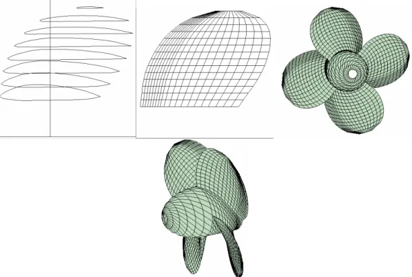
Figure 1: Sectional shape panel layout of the ice class propeller in expanded plan and the rear and side views of this propeller. The pitch ratio at r=0.7R is 0.78 and the hub to diameter ratio is 0.30. This propeller has a rake angle of 10° and minor skew
3. Results and Discussion
There are 20 chordwise panel intervals and 14 equal radial intervals on each blade. Chordwise intervals are arranged by using a semi-cosine function. When a sinusoidal function to control the panel intervals is used, the leading edge panels often have a very large length to width ratio for a dense grid. This affects the accuracy of the results and gives a poor grid connection between the blade root and the hub
P.Liu,B.Colbourne, C. Shin / Journal of Naval Architecture and Marine Engineering 1(2005) 15-20
at the leading edges of a propeller. A remedy was taken to limit the lowest length in the chordwise direction to no less than a predefined value such as 2.5% of the local chord. The semi-cosine function for the chordwise panel arrangement is used for a better resolution when the prediction of the cavity detachment point is required in the cavitation simulation model.
The blade sectional shape, panel arrangement on an expanded blade plan, face side and right side views of the R-class propeller are shown in Figure 1. The geometry details of the propeller may be found in Walker (1996).
Figure 2: Initial position of the ice-class propeller relative to the blade-leading-edge contoured ice wall. The ice wall is fixed and the propeller is approaching the wall at a forward speed of 0.8 m/sec
Predicted and previous experimental Kt and 10Kq
0.00 0.05 0.10 0.15 0.20 0.25 0.30 0.35 0.40 0.20 0.30 0.40 0.50 0.60 0.70 Advance Ratio J K t an d 10K q Exp_Kt Kt w ith NKC 10 Kq w ith NKC Exp_10Kq
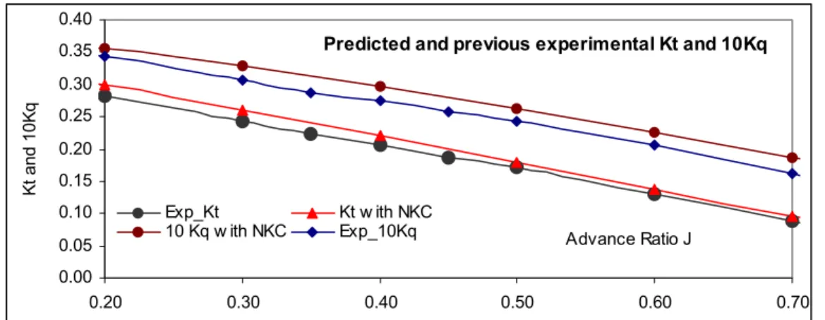
Figure 3: Validation of the prediction by the current method and the previous experimental results in a wide range of load conditions from J=0.2 to 0.7 which correspond to the load factor of from J/[p/D]=0.256 to 0.897
Figure 2 shows the ice-class propeller and the ice blockage contour-fitted to the blade leading edge. The ice blockage width is the same as the propeller diameter and its height is ¼ of the diameter. The top of the ice block is aligned with the maximum height of the blade tip. The rotational speed of the 200-mm propeller model is 10 revolutions per second and the forward speed is 0.8 m/sec so the advance coefficient J is 0.4.
Figure 3 shows themodel validation for open water calculations and measurements (Walker 1996) of the thrust and torque coefficients.
P.Liu,B.Colbourne, C. Shin / Journal of Naval Architecture and Marine Engineering 1(2005) 15-20
In the current method, a numerical Kutta condition is applied. For such a relatively small pitch ratio propeller, implementing the numerical Kutta condition to the current panel method gives a good overall load prediction in a wide range of J values. Results agree well with the experimental data. Figure 4 shows a comparison of the predicted and measured thrust coefficient in an open water condition and the fixed proximity condition. Experimental data is taken from Doucet et al. (1998). All data are computed at J=0.4. The normalized gap values are based on the radius of the propeller model (100mm). Therefore the real distance from the ice to the propeller is 1 mm at a gap value of 1%R. The predicted thrust under the proximity condition is slightly higher than the measurement. At a very small gap value, the predicted results are closer to the second set of experimental data than the first.
Kt vs ice gap in %R 0.10 0.20 0.30 0.40 0.50 0 5 10 15 20 25 30 Gap %R Thrus t coefficient Kt EXP2 EXP1 PROPELLA EXP-ni PROPELLA-ni
Figure 4: Two sets of comparison of thrust coefficient. Set one under open water condition contains two straight lines with + sign for prediction and • for measurement. Set two under proximity condition has three lines for prediction, experimental 1 and 2
Figure 5 shows a torque coefficient comparison with experimental values also taken from also Doucet et al. (1988). For open water flows, the current method gives a slight under prediction on torque at a very small proximity (1-5%R). Under the proximity flow condition, the predicted torque agrees well with the first set of experiments until the gap becomes very small, where the prediction agrees well with the second set of experiments.
Kq vs. gap in %R 0.020 0.025 0.030 0.035 0.040 0.045 0.050 0 5 10 15 20 25 30 Gap %R Torque c oef fi c ie n t Kq PROPELLA-ni EXP-ni PROPELLA EXP1 EXP2
Figure 5: Two sets of comparisons on shaft torque coefficient: one for open water and another for the proximity condition Kt vs ice gap in %R 0.15 0.2 0.25 0.3 0.35 0.4 0.45 0.5 0 5 10 15 20 25 30 Gap %R T h ru st co e ffi ci e n t Kt Fixed Proximity Variable Proximity
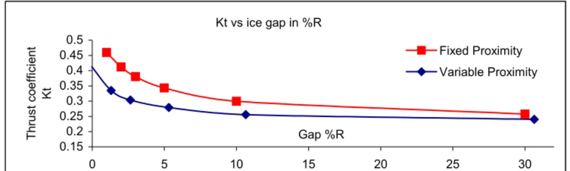
Figure 6: Comparison of thrust coefficient for fixed proximity and variant proximity computations Comparison of the thrust coefficient under fixed proximity and variable proximity conditions is shown in Figure 6. At large gap values, where the propeller is relatively far from the ice blockage, the two thrust coefficients are close. When the gap values decrease, predicted thrust under the variable
P.Liu,B.Colbourne, C. Shin / Journal of Naval Architecture and Marine Engineering 1(2005) 15-20
proximity condition is substantially lower. This indicates that the fixed proximity gives a more conservative estimation of the load fluctuation.
Kq vs. gap in %R 0.025 0.030 0.035 0.040 0.045 0 5 10 15 20 25 30 Gap %R T o rque co e ff ic ie n t Kq Fixed Proximity Variable Proximity
Figure 7: Comparison of torque coefficient for the fixed proximity and variant proximity computations
Kt and 10Kq vs. Gap %R 0 0.05 0.1 0.15 0.2 0.25 0 10 20 30 40 Gap %R50 60 70 80 9 K t and K q 0 Kt 10Kq
Figure 8: Kt and Kq fluctuations on the key blade of the ice-class propeller approaching an ice wall
Pressure coefficicent Cp at 0.7287R w ith a gap of 1.31%R
-1.00 -0.80 -0.60 -0.40 -0.20 0.00 0.20 0.40 0 0.2 0.4 x/c 0.6 0.8 1 -C p Cp pressure side Cp suction side
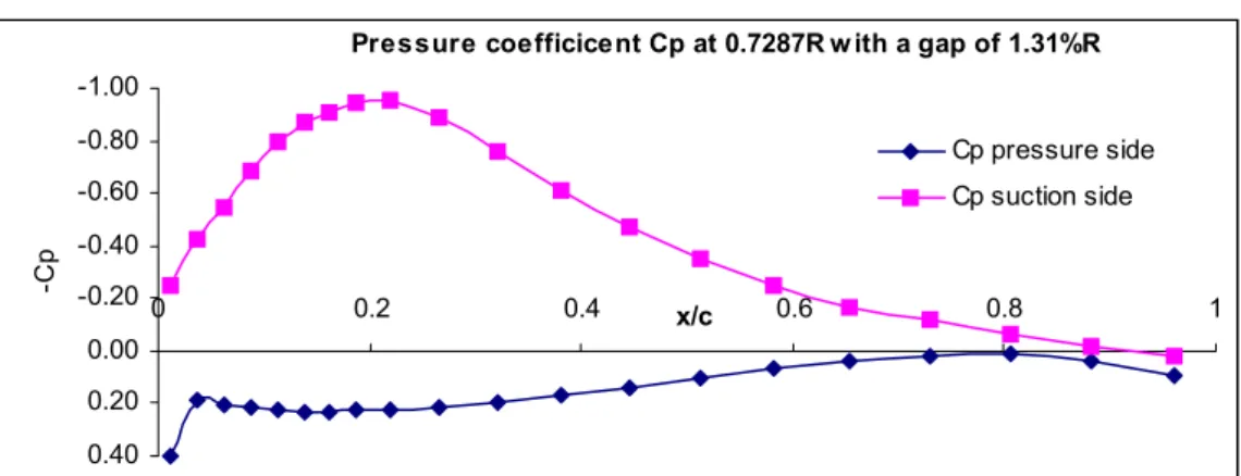
Figure 9: Pressure distribution of the key blade at the 179th time step (1.31%R) at a radial location of r=0.7287R.
A comparison of the torque coefficients under two conditions is shown in Figure 7. It can be seen that throughout the ranges of gap values, the fixed proximity condition yields much larger load fluctuations, which is conservative.
Load fluctuations on the key blade in terms of thrust and torque coefficient at the last two revolutions (revolution two and three) are presented in Figure 8. The last time step of the first revolution corresponds to a gap value of 81.32%R (with an absolute value of 0.074818 m) at which value the key blade is pointing upward. At the last time step of the first revolution, i.e., the 119th time step, the key blade is fully blocked by the ice wall so both torque and thrust are higher than that of the adjacent steps even though the propeller was closer to the ice wall. At the 170th time step corresponding to gap=13.31%R, the key blade entered the ice blockage domain and at the 180th time step the propeller is at the center of the ice wall with a gap values of about 0%R. In this range of interaction, both the thrust and torque coefficients increase dramatically.
Figure 9 shows the pressure distribution at r=0.7287R of the key blade at the 179th time step with a gap value of 1.31%R. The Cp values at the trailing edge could be closer if the pressure difference allowance was set smaller (0.05 in the current computation) for the iterative Kutta condition. However, too small a value of the target value would make the iteration divergence-prone.
P.Liu,B.Colbourne, C. Shin / Journal of Naval Architecture and Marine Engineering 1(2005) 15-20
In computations for the variable proximity case, three revolutions with 60 time steps for each revolution were set. The numerical Kutta condition was used, and for a 500 MHz Xeon Intel processor with 2 GB of RAM on a DELL workstation, a computation took about 36 hours. This run with the above motion and geometry parameters took about 400 MB of RAM, with each additional revolution adding 50 MB. The real time for the model in this simulation is about 0.33 seconds.
5. Conclusion
A transient model for ice-propeller induced hydrodynamic load fluctuation is established. The model is validated with experimental data for open water and fixed proximity conditions and comparisons of results give good agreement. The model is extended to predict load fluctuations with varying proximity and the results indicate a lower load fluctuation compared to the fixed proximity model. At very small gap values, both models give a very high load jump at about the same magnitude.
Acknowledgement
The authors would like to thank the National Research Council Canada for its supports.
References
1. Bose N. (1996). Ice Blocked Propeller Performance Predictions Using a Panel Method. Transactions of the Royal Institute of Naval Architects 138, 213-226.
2. Doucet J.M., Liu P., Bose N. and Veitch B. (1998). Numerical Prediction of Ice-Induced Loads on Ice-Class Screw Propellers Using a Synthesized Contact/Hydrodynamics Code. OERC Report of Ocean Engineering Research Centre, Memorial University of Newfoundland OERC-1998-004 3. Katz J. and Plotkin A. (1991). Low-Speed Aerodynamics, McGraw-Hill, New York
4. Liu P. (1996). A Time-Domain Panel Method for Oscillating Propulsors with both Chordwise and Spanwise Flexibility. Doctoral Thesis, Memorial University of Newfoundland, Canada
5. Liu P. and Bose N. (1998). An Unsteady Panel Method for Highly Skewed Propellers in Non-Uniform Inflow. 22nd ITTC Propulsion Committee Propeller RANS/Panel Method Workshop, 5-6 April, Grenoble, France, 343-349.
6. Liu P, Doucet J.M., Veitch B., Robbins I. and Bose N. (2000). Numerical Prediction of Ice Induced Hydrodynamic Loads on Propellers Due to Blockage. Oceanic Engineering International
4:1, 31-38.
7. Liu P. and Bose N. (2000). Hydrodynamic Characteristics of a Screw-Nozzle-Rudder Assembly. Journal of Computational Fluid Dynamics of Japan 9:1
8. Morino, L. and Kuo, C.-C. (1974). Subsonic Potential Aerodynamics for Complex Configurations: A General Theory. AIAA Journal 12:2, 191-197.
9. Newbury S., Shih, Y.L., Browne R.P., Revill C.R., Kenny S. and Zheng Y. (1993). Experimental and Theoretical Evaluation of Hydrodynamic Pressure during Non-Contact Propeller/Ice Interaction. Institute Report of Institute for Marine Dynamics, National Research Council Canada
IR-1993-15
10. Newman, J.N. (1986). Distributions of sources and normal dipoles over a quadrilateral panel. Journal of Engineering Mathematics 20,113-126.
11. Shih L.Y. and Zheng Y. (1993). Application of 3-D BEM to Time-Dependent Potential Flow Over a Propeller with Ice Blockage at Proximity Condition. Proceedings of the Inaugural Conference of the CFD Society of Canada, PQ, Canada.
12. Veitch B. (1995). Prediction of Ice Contact Forces on a Marine Screw Propeller during the Propeller-Ice Cutting Process. Acta Polytechnica Scandinavica, Mechanical Engineering Series, Espoo, Finland 118
13. Veitch B., Bose N., Meade C. and Liu P. (1997). Prediction of Hydrodynamic and Ice Contact Loads on Ice-Class Screw Propellers, Proceedings of the 16th International Conference on Offshore Mechanics and Arctic Engineering, American Society of Mechanical Engineers 4, 119-125.
14. Walker D. (1996). The Influence of Blockage and Cavitation on the Hydrodynamic Performance of Ice Class Propellers in Blocked Flow, Doctoral Thesis, Memorial University of Newfoundland, Canada
20
View publication stats View publication stats