Publisher’s version / Version de l'éditeur:
8th International Conference on Trends in Welding Research, 2008-06-30
READ THESE TERMS AND CONDITIONS CAREFULLY BEFORE USING THIS WEBSITE.
https://nrc-publications.canada.ca/eng/copyright
Vous avez des questions? Nous pouvons vous aider. Pour communiquer directement avec un auteur, consultez la première page de la revue dans laquelle son article a été publié afin de trouver ses coordonnées. Si vous n’arrivez pas à les repérer, communiquez avec nous à [email protected].
Questions? Contact the NRC Publications Archive team at
[email protected]. If you wish to email the authors directly, please see the first page of the publication for their contact information.
NRC Publications Archive
Archives des publications du CNRC
This publication could be one of several versions: author’s original, accepted manuscript or the publisher’s version. / La version de cette publication peut être l’une des suivantes : la version prépublication de l’auteur, la version acceptée du manuscrit ou la version de l’éditeur.
Access and use of this website and the material on it are subject to the Terms and Conditions set forth at
Welding Simulation of Cast Aluminium A356
Pham, X-T.; Gougeon, P.; Gagnon, F-O.
https://publications-cnrc.canada.ca/fra/droits
L’accès à ce site Web et l’utilisation de son contenu sont assujettis aux conditions présentées dans le site LISEZ CES CONDITIONS ATTENTIVEMENT AVANT D’UTILISER CE SITE WEB.
NRC Publications Record / Notice d'Archives des publications de CNRC:
https://nrc-publications.canada.ca/eng/view/object/?id=d7f3d7cb-ccd8-4c30-a907-6dc043a86acd https://publications-cnrc.canada.ca/fra/voir/objet/?id=d7f3d7cb-ccd8-4c30-a907-6dc043a86acd
Welding Simulation of Cast Aluminium A356
X-T. Pham*, P. Gougeon and F-O. Gagnon
Aluminium Technology Centre, National Research Council Canada Chicoutimi, Quebec, Canada
*
Abstract
Welding of cast aluminium hollow parts is a new promising technical trend for structural assemblies. However, big gap between components, weld porosity, large distortion and risk for hot cracking need to be dealt with. In this paper, the MIG welding of aluminium A356 cast square tubes is studied. The distortion of the welded tubes was predicted by numerical simulations. A good agreement between experimental and numerical results was obtained.
Introduction
Aluminium structures become more and more popular in industries thanks to their light weights, especially in the automotive manufacturing industry. Moreover, welding of cast aluminium hollow parts is a new promising technical trend for structural assemblies [1-3]. However, it may be very challenging due to many problems such as big gap between components, weld porosity, large distortion and risk for hot cracking [4,5]. Due to local heating, complex thermal stresses occur during welding; residual stress and distortion result after welding. In this paper, the aluminium A356 cast tube MIG welding is studied. The software Sysweld [6] was used for welding simulations. The objective is to validate the capability of this software in predicting the distortion of the welded tubes in the presence of large gaps. In this work, the porosity of welds was checked after welding using the X-ray technique. The heat source parameters were identified based on the weld cross-sections and welding parameters. Full 3D thermal metallurgical mechanical simulations were performed. The distortions predicted by the numerical simulations were compared to experimental results measured after welding by a CMM machine.
Experiments
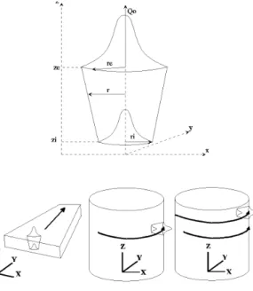
Experimental setupTwo square tubes are made of A356 by sand casting and then machined. They are assembled by four MIG welds, named W1 to W4. Their dimensions and the welding configuration are
depicted in Figure 1. Both small (inner) and large (outer) tubes are well positioned on a fixture using v-blocks as shown in Figure 2. The dimensions of the tubes make a peripheral gap of 1 mm between them. This fixture is fixed on a positioner that allows the welding process to be carried out always in the horizontal position. The length of each weld is of 35 mm. The Fronius welding head, which is mounted on a Motoman robot, was used for the MIG welding process. Table 1 indicates the parameters of the welding process for this welding configuration.
Table 1: MIG welding parameters.
Voltage Amperage Speed Thick1 Thick2 Gap
(V) (A) (m/min.) (mm) (mm) (mm)
23 260 1.25 4 4 1
Testing
The porosity of welds was observed before and after welding using the X-ray technique to check the quality of these welds according to the standard ASTM E155. The whole welded tubes were then tested by traction on a MTS testing machine. The final dimensions of the welded tubes are measured on a CMM machine at many points on the tubes. The distortion of the welded tubes is determined by comparing the final positions with the initial positions of the tubes.
Numerical analysis
In Sysweld, a welding analysis is performed based on a weak-coupling formulation between the heat transfer and mechanical problems. Only the thermal history will affect on the mechanical properties, but not in reverse direction. Therefore, a thermal metallurgical mechanical analysis is divided into two steps. The first step is a thermal metallurgical analysis, in which the heat transferred from the welding source makes phase changes during the welding process. The results of temperature and phase changes from the first step are then used as input for the second analysis. It is a pure thermo-elasto-plastic simulation [6].
Heat source model identification
Before running a welding simulation, it is necessary to determine the parameters of the heat source model. This is called heat source fitting. Actually, it is a thermal simulation using this heat source model in the steady state, which is
combined with an optimization tool to obtain the parameters of the heat source. Figure 3 presents the form of a 3D conical heat source of which the energy distribution is described in Eq (1) as follows:
a) b)
Figure 1: Tube welding configuration: a) cross-section view, b) tube dimensions.
Figure 2: Experimental setup for tube welding.
Y
W1 W2 W3 W4Z
Outer tube, thickness 4mm, length~ 500mm Inner tube, thickness 4mm, length~ 500mm Gap 1mm 60mm 38mm 50mm Gap 1mm2 0 2 0 exp r F Q r ⎧ ⎫ ⎪ ⎪ ⎬ = ⎨− ⎪ ⎪ ⎩ ⎭ 2 ) (1) in which denotes the power density; and are defined
by 0 Q r r, 0 (2) 2 2 0 0 ( ) ( r = x−x + x−x −vt and 0 0 ( )( ( ) e i e e e i r r z z z r r z z − − + = − − ) (3) where (x y z0, 0, 0) is the origin of the local coordinate system
of the heat source; and the radius of the heat source at
the positions and , respectively; the welding speed and the time. e r ri e z zi v t
In this study, a metallographic cross-section has been used to identify the heat source parameters as shown in Figure 4. The use of a 3D conical heat source fits very well the weld cross-section. The mesh size in the cross-section is around 0.5 mm for this case. The finer is the mesh, the more accurate is the shape of the melting pool, but the longer is the simulation.
Figure 3: 3D conical heat source (Sysweld).
a) b)
Analysis model
The mesh of the tubes was created in Hypermesh 7.0. Sysweld 2007 has been used as solver and pre/post processor. A full 3D thermal metallurgical mechanical analysis with brick and prism elements. Two welding sequences have been done such as W1/W2/W3/W4 and W1/W3/W2/W4. The tubes are clamped using four v-blocks during the welding, two for each tube. In the simulations, the positions where the tubes are in contact against the surfaces of the v-blocks are considered as fixed conditions (i.e. Ux = Uy = Uz = 0). In the release phase, the tubes are free from the v-blocks.
Results
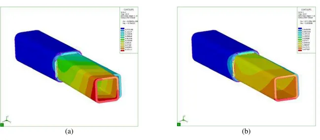
The distortion of the welded tube is measured when it is released from the constraints. The distortion is determined by measuring the displacement of the small tube on the top and lateral surfaces along the centre line of the tube. These measures are relative to the large tube. Figures 5a-b depict the distortion predicted by the numerical simulations of the sequence W1/W2/W3/W4 and W1/W3/2/W4, respectively. Good agreements between experimental and numerical results were obtained in the two welding sequences as indicated in Tables 2-3, in both the distortion tendency and distortion range of the process variation.
(a) (b)
Figure 5: Tube distortion (Norm U):
(a) Sequence W1/W2/W3/W4, (b) Sequence W1/W3/W2/W4.
Table 2: Distortion result comparison (welding sequence W1/W2/W3/W4)
Displacements (mm)
Uy Uz Experimental from -0.4 to -0.59 from -0.35 to -0.51
3D simulation -0.4 -0.51
Table 3: Distortion result comparison (welding sequence W1/W3/W2/W4)
Displacements (mm)
Uy Uz Experimental from -0.07 to -0.11 from -0.12 to -0.21
(a) (b)
Figure 6: State of stresses Sxx (a) Clamped, (b) Released. (Red = positive, Blue = negative)
(a) (b)
Figure 7: State of stresses Sxy (a) Clamped, (b) Released. (Red = positive, Blue = negative)
(a) (b)
Figure 8: State of stresses Sxz (a) Clamped, (b) Released. (Red = positive, Blue = negative)
Figures 6-8 shows the state of the stresses of the welded tubes at room temperature for the sequence W1/W2/W3/W4 after welding when clampled and released from constraints (x is the direction along the axe of the welded tube). To show how the welded tube is distorted, positive-negative values are used instead of the true values of stresses. The distortion of the welded tube can be explained as the new equilibrium position due to the residual stresses when there is no external load. It is remarked that in the presence of large gaps, the distortion of the welded tube is very likely in the rotational mode around local welds.
Conclusions
The MIG welding is very good for assembling aluminium cast tubes (hollow parts) in the presence of large gaps. The 3D thermal metallurgical mechanical simulation of
the cast tube welding using Sysweld has been validated. A very good agreement between numerical and experimental results was obtained for both the distortion tendency and distortion range.
The welding sequence has a major influence on the distortion of the welded structure. It turns out that the optimization of the welding sequences for a reasonable distortion of a welded structure with a large number of welds becomes very important.
Acknowledgments
The authors would like to thank gratefully Rio Tinto Alcan and General Motor for financial and technical supports, particularly Martin Fortier and Pei-Chung Wang. Also, the authors are grateful to Welding Team at ATC (Audrey Boily, Martin Larouche, François Nadeau and Mario Patry) for experimental works.
References
1. K-H. Von Zengen, Aluminium in future cars – A
challenge for materials science, Materials Science Forum, 519-521 (Part 2), 1201-1208 (2006).
2. S. Wiesner S., M. Rethmeier and H. Wohlfart, MIG and
laser welding of aluminium alloy pressure die cast parts with wrought profiles, Welding International, 19 (2),
130-133 (2005).
3. R. Akhter, L. Ivanchev, C.V.Rooyen, P. Kazadi and H.P. Burger, Laser welding of SSM Cast A356 aluminium
alloy processed with CSIR-Rheo technology, Solid State Phenomena, 116-117, 173-176 (2006).
4. J.F. Lancaster, Metallurgy of welding, Abington Publishing (1999).
5. Φ. Grong, Metallurgical modelling of welding, The institute of materials (1997).