Publisher’s version / Version de l'éditeur:
Electrochemistry Communications, 31, pp. 120-124, 2013-03-22
READ THESE TERMS AND CONDITIONS CAREFULLY BEFORE USING THIS WEBSITE.
https://nrc-publications.canada.ca/eng/copyright
Vous avez des questions? Nous pouvons vous aider. Pour communiquer directement avec un auteur, consultez la
première page de la revue dans laquelle son article a été publié afin de trouver ses coordonnées. Si vous n’arrivez pas à les repérer, communiquez avec nous à [email protected].
Questions? Contact the NRC Publications Archive team at
[email protected]. If you wish to email the authors directly, please see the first page of the publication for their contact information.
NRC Publications Archive
Archives des publications du CNRC
This publication could be one of several versions: author’s original, accepted manuscript or the publisher’s version. / La version de cette publication peut être l’une des suivantes : la version prépublication de l’auteur, la version acceptée du manuscrit ou la version de l’éditeur.
For the publisher’s version, please access the DOI link below./ Pour consulter la version de l’éditeur, utilisez le lien DOI ci-dessous.
https://doi.org/10.1016/j.elecom.2013.03.018
Access and use of this website and the material on it are subject to the Terms and Conditions set forth at
A capillary water retention effect to improve medium-temperature fuel cell performance
Lee, So Young; Shin, Dong Won; Wang, Chenyi; Lee, Kang Hyuck; Guiver, Michael D.; Lee, Young Moo
https://publications-cnrc.canada.ca/fra/droits
L’accès à ce site Web et l’utilisation de son contenu sont assujettis aux conditions présentées dans le site LISEZ CES CONDITIONS ATTENTIVEMENT AVANT D’UTILISER CE SITE WEB.
NRC Publications Record / Notice d'Archives des publications de CNRC: https://nrc-publications.canada.ca/eng/view/object/?id=3ac5b5ba-6df7-46d1-99f3-b7f50dfa10ac https://publications-cnrc.canada.ca/fra/voir/objet/?id=3ac5b5ba-6df7-46d1-99f3-b7f50dfa10ac
Graphical abstract
A capillary water retention effect to improve medium-temperature fuel cell performance
So Young Lee,Dong Won Shin,Chen Yi Wang,Kang Hyuk Lee,Michael D. Guiver, Young Moo Lee
Small hydrophilic domain sizes (< 5 nm) improve fuel cell performance due to capillary water retention effect at 120 oC, 35%RH
Highlights
A capillary water retention effect to improve medium-temperature fuel cell performance
So Young Lee,Dong Won Shin,Chen Yi Wang,Kang Hyuk Lee,Michael D. Guiver, Young Moo Lee
Morphology in sulfonated polymer membrane influences fuel cell performance at >80 oC.
Phase separated morphology and hydrophilic domain size of three types of sulfonated poly(arylene ether sulfone)s (SPAES) improve the medium temperature fuel cell performance.
Graft SPAES (G-SPAES) with small hydrophilic domain sizes (< 5 nm) shows excellent fuel cell performance due to capillary water retention effect at 120
oC, 35%RH.
1
A capillary water retention effect to improve medium-temperature
1fuel cell performance
23
So Young Lee 1,Dong Won Shin, 1Chen Yi Wang, 2 Kang Hyuk Lee, 2 Michael D. Guiver, 2,3 4
Young Moo Lee1,2,* 5
6
1
Department of Chemical Engineering, Hanyang University, Seoul, Republic of Korea, 133-791. 7
2
WCU Department of Energy Engineering, Hanyang University, Seoul, Republic of Korea, 133-8
791. 9
3
National Research Council Canada, Ottawa, Ontario, K1A 0R6, Canada. 10
11
Abstract
12
We demonstrate for the first time that small and narrow hydrophilic conducting domain 13
morphology in sulfonated hydrocarbon membranes leads to much better fuel cell performance at 14
medium temperature and low humidity conditions than those with larger hydrophilic domains. A 15
comparison of three types of sulfonated poly(arylene ether sulfone)s (SPAES) with random, 16
block, and graft architecture indicates that small hydrophilic domain sizes (< 5 nm) appear to be 17
important in supporting water retention under low relative humidity (RH) conditions intended for 18
medium temperature (> 100oC) fuel cell applications. The graft copolymer outperformed both a 19
random copolymer and multiblock copolymer at 120 °C and 35% RH fuel cell operating 20
conditions due to capillary condensation of water within the 3-5 nm hydrophilic domains. 21
*c. Manuscript
2 1
Keywords: fuel cell; polymer electrolyte membrane; medium-temperature; sulfonated 2
pol(arylene ether sulfone); morphology; 3
4
1. Introduction
5
Proton exchange membrane fuel cells (PEMFCs) are being studied as clean energy 6
conversion devices due to their high efficiency and environmental friendliness.[1] In particular, 7
medium-temperature proton exchange membrane fuel cells (MT-PEMFCs), operated above 100 8
o
C, have some benefits. [1-3] Carbon monoxide (CO) impurities in the hydrogen feed gas affect 9
the fuel cell performance by adsorbing to the platinum surface and poisoning the platinum 10
electro-catalyst. The adsorption of CO is lessened at elevated temperature leading to higher 11
resistance of the catalyst to fuel impurities; thus operation at high temperature would simplify the 12
fuel cell system by reducing the level of hydrogen purification necessary. In recent years, MT-13
PEMFCs have been recognized as a promising solution to meet the technical challenges for 14
transportation applications. In 2009, the US Department of Energy (DOE) set the target for PEM 15
performance for operation for 500 h at 120 oC without external humidification.[4] However, 16
there are challenging technical obstacles to overcome, such as low proton conductivity and cell 17
performance drop due to the evaporation of water molecules. 18
It is well-known that phase-separated morphology affects PEMFC performance under 19
partially hydrated conditions or at elevated temperature [5, 6]. Among PEMs with various types 20
of architecture, block copolymers and aligned polymers have well-defined hydrophilic ionic 21
channels, which increase the connectivity between the hydrophilic domains and improve proton 22
3
conductivity and fuel cell performance under low relative humidity conditions. Also, well-1
defined morphology enhances the self-diffusion coefficient of water, resulting in the better 2
retention of free water within the membrane. 3
In the present work, three representative sulfonated poly(arylene ether sulfone)s (SPAES) 4
having different architecture and microstructures were used to investigate the influence of 5
polymer morphology on electrochemical properties, leading to insight into the effective 6
molecular design of sulfonated aromatic PEMs for MT-PEMFC. To this end, water transport, 7
proton conductivity, and electrochemical polarization behavior of random, multiblock, and graft 8
SPAES membranes were investigated under controlled temperature and RH. 9
10
2. Experimental Section
11
2.1 Preparation of Random and Multiblock and Grafting SPAES Membranes
12
Sulfonated PEMs with three types of polymer architecture, random and multiblock 13
copolymer (R-SPAES and B-SPAES) [7-9] and grafted side chain polymer (G-SPAES) [10] 14
were prepared by nucleophilic aromatic substitution reaction. B-SPAES was synthesized in a 15
similar manner with phenoxide terminated hydrophilic oligomer and halide terminated 16
hydrophobic oligomer. 17
Three types of SPAESs were dissolved as 10-15 wt% solutions in DMSO or DMAc. The 18
polymer solutions were filtered and cast onto glass plates. The cast solutions were dried in an 19
oven at 60 oC in an inert environment for at least 12 h and then residual solvent was removed 20
under vacuum at 120 oC. The salt form (K+ form) membranes were acidified by boiling in a 0.5 21
4
M sulfuric acid solution for 2 h, followed by washing with boiling deionized water for 2 h to 1
convert membranes into the acid form (H+ from). 2
2.2 Characterization and Measurements.
3
For transmission electron microscopy (TEM) observation, the membranes were stained 4
with lead ion (Pb2+) by immersing 0.5 M lead acetate aqueous solution. The stained membranes 5
were embedded in epoxy resin, microtomed to 70 nm thickness with a RMCMTX Ultra 6
microtome, and placed on copper grids. TEM images were taken with a Carl Zeiss LIBRA 120 7
energy filtering transmission electron microscope using an accelerating voltage of 120 kV. 8
Proton conductivity of each membrane sample at various temperature and relative humidity 9
conditions was estimated using a 4-probe conductivity cell connected with an electrochemical 10
interface (Solartron 1287) in combination with an impedance/gain-phase analyzer (Solartron 11
1260) in the frequency range from 10 Hz to 100 kHz. 12
The membrane electrode assembly (MEA) with an active area of 5 cm2 and Pt loading of 13
0.5 mg cm-2 was fabricated via the screen printing method [11]. The single cell was mounted in a 14
commercial fuel cell testing station (SMART PEMFC test system, WonATech, Seoul, Korea) 15
which was supplied with temperature and humidity controlled gases. H2 and O2 were supplied at
16
a flow rate of 100 cm3 min-1 at various cell temperatures (80 oC, 100 oC, and 120 oC) and relative 17
humidity conditions (100%, 85%, and 35%) at a 1.5 atm back-pressure state. 18
19
3. Results & Discussion
20
The synthesis of three representative SPAESs membranes was confirmed in previous 21
studies [7-10]. The three SPAES were synthesized to have similar IECw values (1.70~1.75 meq
5
g-1) by carefully controlling the feed ratio of sulfonated to nonsulfonated monomers, and the 1
length of the block segments. 2
The cross-sectional nanophase-morphologies of three SPAESs were investigated using 3
transmission electron microscopy (TEM) for lead-stained samples, as shown in Figure 1.In these 4
images, the dark phase represents hydrophilic domains containing sulfonic acid groups, which 5
were exchanged with lead cations. Nafion® 212 membrane has distinct and well-connected 6
hydrophilic clusters of ca. 5~10 nm size, as reported earlier [12]. Three SPAESs exhibited 7
different hydrophilic domain sizes and connectivity despite their similar IEC values. R-SPAES 8
shows relatively featureless morphology indicating the absence of well-defined ionic cluster, 9
with the hydrophilic domains distributed randomly within the hydrophobic matrix, shown as the 10
bright phase (Figure 1a,b). In contrast, B-SPAES (Figure 1c,d) and G-SPAES (Figure 1e,f) 11
exhibit well-defined, nanophase-separated morphologies, which are responsible for high proton 12
conductivity at low humidity. Especially at higher magnification (Figure 1d, f), the G-SPAES 13
membrane exhibits narrower and smaller interconnected hydrophilic channel sizes of ca. 2-5 nm, 14
while B-SPAES exhibits the largest interconnected hydrophilic channel sizes in the range of ca. 15
8-15 nm. 16
The hydrophilic domain size significantly affects water retention and release in PEMs, 17
particularly at low RH and elevated temperature (>100 oC) conditions. Park et al. reported that 18
aliphatic PEMs with hydrophilic domain widths of less than 5 nm showed an increase in proton 19
conductivity with increasing temperature under low RH conditions, due mainly to the effect of 20
capillary condensation and confinement of water within the narrow hydrophilic domains [13, 14]. 21
In this regard, G-SPAES with narrower hydrophilic channel size ca. 2-5 nm is expected to 22
6
maintain high proton conductivity by high water retention than B-SPAES particularly under high 1
temperature (>100 oC) and low humidity conditions. 2
The humidity dependence of proton conductivity for the sulfonated aromatic PEMs and 3
Nafion® 212 membrane is compared at 80 oC, as shown in Figure 2a. Proton conductivities of the 4
membranes decreased, as applied humidity was reduced from 100 % RH to 30 % RH, indicating 5
that the presence of water in the membrane enhances ionic conduction by both Grotthuss and 6
vehicular mechanism. The conductivity of Nafion® 212 and R-SPAES showed significant 7
declines compared with that of B-SPAES and G-SPAES at above 50% RH, implying that their 8
proton conductivity was more dependent on humidity than that of B-SPAES and G-SPAES. 9
Interestingly, below 50% RH, G-SPAES showed a more stable ionic conductivity than that of B-10
SPAES and its proton conductivity is comparable to that of Nafion® 212. 11
This similar proton conduction behavior was also exhibited in Figure 2b and plotted as 12
function of temperature at ambient RH, which decreased from 100 % RH to 35% RH as 13
temperature increased from 80 oC to 120 oC. The proton conductivities of the three SPAESs and 14
Nafion® 212 were comparable to one another at 80 oC and 100% RH. As the temperature was 15
increased, both B-SPAES and G-SPAES were able to better retain proton conductivity compared 16
with R-SPAES, because of their well-ordered phase separated morphologies. Although B-17
SPAES had higher proton conductivity than that of G-SPAES below 100 oC, G-SPAES exhibited 18
the highest proton conductivity of about 0.011 S cm-1 at 120 oC. The more stable proton 19
conduction behavior of G-SPAES under low RH conditions may result from an increase in water 20
retention capability via synergistic effects of high sulfonic acid concentration ((IECv(wet)) = ~1.86
7
meq cm-3) [10] and capillary hydrophilic domains enhancing strong complexation of water 1
molecules with sulfonic acid groups. 2
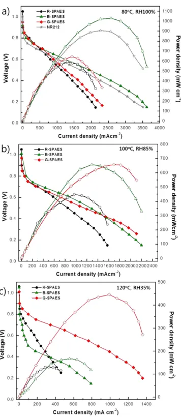
To investigate the impact of the different polymer morphologies on fuel cell performance, 3
the current-voltage polarization characteristics of H2/O2 single cells using each of SPAESs, were
4
evaluated at three different temperatures and RH conditions (Figure 3). As shown in Figure 3a, 5
the current voltage polarization of three SPAESs and Nafion® 212 membrane were obtained at 6
80 oC and 100% RH. As anticipated from the proton conductivity data and well-developed 7
hydrophilic channels, the performance of the B-SPAES was superior to that of other SPAES and 8
Nafion® 212. At 0.5 V, its current density and maximum power density were ~160%, ~170% and 9
~115% higher than those ofG-SPAES, R-SPAES and Nafion®
212, respectively. 10
However, when the cell temperature was further increased and RH was correspondingly 11
reduced, the current-voltage polarization curve of B-SPAES declined rapidly compared with 12
those of G-SPAES and R-SPAES (Figure 3b and 3c). This drastic reduction in single cell 13
performance with decreasing RH (or dry states) is typically observed in many sulfonated 14
hydrocarbon PEMs and is associated with the evaporation of proton carrier water molecules. For 15
example, when the cell temperature and RH were changed from 100 oC and 85% RH to 120 oC 16
and 35%, current density and maximum power density of B-SPAES at 0.5 V sharply decreased 17
from 1289 mA cm-2 and 650 mW cm-2 to 104 mA cm-2 and 150 mW cm-2. 18
Interestingly, in the case of G-SPAES, the extent of reduction in cell performance was 19
largely alleviated with the operation condition changing from 100 oC and 85% RH to 120 oC and 20
35%, which is probably due to water retention capability of small hydrophilic domain size (2-5 21
nm) in the polymer. Wide and large well-developed hydrophilic domains of B-SPAES (8-15 nm) 22
8
had excellent proton transport properties at a temperature of 100 oC and 85% RH conditions. 1
However, as the temperature increased above 100 oC, the wider channels led to the proton carrier 2
water molecules being lost more readily, resulting in B-SPAES performing more poorly at 120oC 3 and 35% RH. 4 5 4. Conclusions 6
Morphology and hydrophilic domain size were compared for three SPAESs copolymers 7
with random, multiblock and grafted side-chain architecture and were found to significantly 8
affect the proton conduction, particularly at elevated temperatures and low RH conditions. B-9
SPAES and G-SPAES, having well-defined, nanophase-separated morphologies exhibited less 10
dependence on humidity; thus they showed relatively good proton conductivity at 80 oC and low 11
RH compared with R-SPAES and Nafion® 212. G-SPAES, with a narrow hydrophilic domain 12
size of less than 5 nm showed higher water retention properties for proton transport, particularly 13
at 120 oC and low RH compared with that of B-SPAES having a relatively large and wider 14
hydrophilic domain size of about 8-15 nm. Thus the fuel cell performance of G-SPAES 15
performed much better than that of B-SPAES, R-SPAES and Nafion® 212 at 120 oC and 35 16
RH%. Phase separated morphology and hydrophilic domain size plays a key role in improving 17
the medium-temperature fuel cell performance. 18
19
Acknowledgements
20
This work was supported by the Joint Research Project funded by the Korea Research Council of 21
Fundamental Science & Technology (KRCF), Republic of Korea and the WCU (World Class 22
University) program through the government of Korea (No. R31-2008-000-10092-0) 23
9 1
References
2
[1] C.H. Park, C.H. Lee, M.D. Guiver, Y.M. Lee, Prog. Polym. Sci., 36 (2011) 1443. 3
[2] S. Bose, T. Kuila, X.L.N. Thi, N.H. Kim, K.T. Lau, J.H. Lee, Prog. Polym. Sci., 36 (2011) 4
813. 5
[3] Q.F. Li, R.H. He, J.O. Jensen, N.J. Bjerrum, Chem. Mater., 15 (2003) 4896. 6
[4] N.Gerland, J. Kopasz, DOE View of Advanced Materials for Fuel Cell, Advance in Materials 7
for Proton Excange Membrane Fuel Cell Systems 2011 8
[5] M.L. Einsla, Y.S. Kim, M. Hawley, H.-S. Lee, J.E. McGrath, B. Liu, M.D. Guiver, B.S. 9
Pivovar, Chem. Mater., 20 (2008) 5636. 10
[6] M. Ingratta, E.P. Jutemar, P. Jannasch, Macromolecules, 44 (2011) 2074. 11
[7] M. Lee, J.K. Park, H.-S. Lee, O. Lane, R.B. Moore, J.E. McGrath, D.G. Baird, Polymer, 50 12
(2009) 6129. 13
[8] H.-S. Lee, A. Roy, O. Lane, S. Dunn, J.E. McGrath, Polymer, 49 (2008) 715. 14
[9] C.H. Lee, K.A. Min, H.B. Park, Y.T. Hong, B.O. Jung, Y.M. Lee, J. Membr. Sci., 303 (2007) 15
258. 16
[10] C. Wang, N. Li, D.W. Shin, S.Y. Lee, N.R. Kang, Y.M. Lee, M.D. Guiver, Macromolecules, 17
44 (2011) 7296. 18
[11] D.S. Hwang, C.H. Park, S.C. Yi, Y.M. Lee, Int. J. Hydrogen Energy, 36 (2011) 9876. 19
[12] W.Y. Hsu, T.D. Gierke, Macromolecules, 15 (1982) 101. 20
[13] M.J. Park, K.H. Downing, A. Jackson, E.D. Gomez, A.M. Minor, D. Cookson, A.Z. Weber, 21
N.P. Balsara, Nano Lett., 7 (2007) 3547. 22
[14] X.-M. Yan, P. Mei, Y. Mi, L. Gao, S. Qin, Electrochem. Commun., 11 (2009) 71. 23
24 25
1 1 2 3 4 5 6 7 8
Figure 1. TEM images of sulfonated hydrocarbon PEMs; a.SPAES b. Magnified image of R-9
SPAES, c. B-SPAES, d. Magnified image of B-SPAES , e. SPAES, f. Magnified image of G-10 SPAES 11 12 13 14 d. Figure(s)
2 1 2 3 4 5
Figure 2. (a) Proton conductivity of SPAESs and Nafion® 212 at 80 oC as function of RH%, and 6
(b) proton conductivity of SPAESs and Nafion® 212 as a function of temperature and RH% 7 8 9 10 11 12 13 14 15 16 17 18
3 1
Figure 3. The H2/O2 single cell performance of SPAES PEMs at different temperatures and RH
2
conditions. Note that single cell performance of Nafion® 212 membrane was not obtained above 3
80oC temperature, due to thermal dehydration and deformation resulting from low Tg.