Publisher’s version / Version de l'éditeur:
Journal of the Electrochemical Society, 159, 4, pp. A331-A335, 2012-01-18
READ THESE TERMS AND CONDITIONS CAREFULLY BEFORE USING THIS WEBSITE. https://nrc-publications.canada.ca/eng/copyright
Vous avez des questions? Nous pouvons vous aider. Pour communiquer directement avec un auteur, consultez la première page de la revue dans laquelle son article a été publié afin de trouver ses coordonnées. Si vous n’arrivez pas à les repérer, communiquez avec nous à PublicationsArchive-ArchivesPublications@nrc-cnrc.gc.ca.
Questions? Contact the NRC Publications Archive team at
PublicationsArchive-ArchivesPublications@nrc-cnrc.gc.ca. If you wish to email the authors directly, please see the first page of the publication for their contact information.
NRC Publications Archive
Archives des publications du CNRC
This publication could be one of several versions: author’s original, accepted manuscript or the publisher’s version. / La version de cette publication peut être l’une des suivantes : la version prépublication de l’auteur, la version acceptée du manuscrit ou la version de l’éditeur.
For the publisher’s version, please access the DOI link below./ Pour consulter la version de l’éditeur, utilisez le lien DOI ci-dessous.
https://doi.org/10.1149/2.004204jes
Access and use of this website and the material on it are subject to the Terms and Conditions set forth at
Optimization of synthesis conditions for LiFePO4/C nanocomposites by
dimethyl sulfoxide assisted solution-phase method
Chang, Zhaorong; Tang, Hongwei; Liu, Yao; Yuan, Xiao Zi; Wang, Haijiang;
Gao, Shuyan
https://publications-cnrc.canada.ca/fra/droits
L’accès à ce site Web et l’utilisation de son contenu sont assujettis aux conditions présentées dans le site LISEZ CES CONDITIONS ATTENTIVEMENT AVANT D’UTILISER CE SITE WEB.
NRC Publications Record / Notice d'Archives des publications de CNRC:
https://nrc-publications.canada.ca/eng/view/object/?id=a398a3cb-004e-4eea-89dd-61d5f66cc09f
https://publications-cnrc.canada.ca/fra/voir/objet/?id=a398a3cb-004e-4eea-89dd-61d5f66cc09f
Optimization of Synthesis Conditions for LiFePO
4/C
Nanocomposites by Dimethyl Sulfoxide Assisted
Solution-Phase Method
Zhaorong Chang,a,zHongwei Tang,aYao Liu,aXiao Zi Yuan,b Haijiang Wang,b,∗and Shuyan Gaoa,z
aCollege of Chemistry and Environmental Science, Henan Normal University, Xinxiang 453007, China bInstitute for Fuel Cell Innovation, National Research Council of Canada, Vancouver, BC, Canada V6T 1W5
Olivine-type LiFePO4is synthesized by a solution-phase method, using dimethyl sulfoxide (DMSO) as a boiling point raiser and
crystal growth inhibitor under ambient pressure and low temperature for a short time. The crystalline structure and morphology of the composites are characterized by X-ray diffraction (XRD) and scanning electron microscopy (SEM), respectively. By analyz-ing the ratio of solvent to water, reactant concentration, reaction time, sinteranalyz-ing time, and temperature we determine the optimal conditions for synthesizing LiFePO4/C nanocomposites, which are as follows: DMSO:water = 1:1, reactant concentration 1 M,
reaction time 2 h, mixed with a certain amount of glucose and sintered at 600◦C under a 5% H
2–95% N2atmosphere for 3 h.
The LiFePO4/C thus prepared has a well developed olivine-type structure, small crystals, and a narrow size distribution.
Electro-chemical performance tests show that the special capacity of LiFePO4/C at discharge rates of 0.2 C and 1 C is 157.7 mAh g−1and
142.5 mAh g−1, respectively. A special capacity of 126 mAh g−1at 5 C and 104 mAh g−1at 10 C is even achievable, with no
signifi-cant capacity fading after 200 cycles, and the material delivers a good high-rate discharge property and excellent cycling performance. © 2012 The Electrochemical Society. [DOI:10.1149/2.004204jes] All rights reserved.
Manuscript submitted September 26, 2011; revised manuscript received November 28, 2011. Published January 18, 2012.
LiFePO4 is regarded as a promising cathode material for lithium
ion batteries due to its high theoretical capability (170 mAh g−1),
ble discharge platform (3.4 V), relatively low cost, excellent heat sta-bility, low toxicity, reasonable safety, and good structural stability.1–3 However, LiFePO4has two main defects: slow lithium ion diffusion
across the LiFePO4/FePO4interface and low electronic conductivity,
which leads to poor high-rate discharge performance.4,5 Previously, two approaches have been reported to address these defects. One is to improve Li+ion diffusion by doping with Mg, Mn, V, and Ti to
reduce the particle size.6–10The other is to improve electrical conduc-tivity by coating the LiFePO4particle surface with amorphous carbon,
and nanosized Ag and Cu.11–14Recent studies show that reducing the size of LiFePO4 can shorten the lithium ion diffusion channel in
the solid phase, which is beneficial for the intercalation and dein-tercalation of lithium ions; this is very important for improving the high-rate discharge property.2,15,16To date, many different methods have been developed to synthesize LiFePO4with fine, uniform
parti-cles, including sol-gel routes,17co-precipitation,18spray drying,19and so on. Although these methods can improve the degree to which the materials are mixed, the process of drying the precursor is compli-cated and the product still requires lengthy heat-treatment. Recently, some researchers have proposed synthesizing LiFePO4
nanocompos-ites in the pure liquid phase, such as by hydrothermal/solvothermal processes.20–24Ou et al.25synthesized LiFePO
4through a
hydrother-mal reaction using FeSO4·7H2O, H3PO4, and LiOH · H2O as the
starting materials at 180◦C for 6 h, followed by sintering at 750◦C
under a 5% H2–95% N2 atmosphere for 6 h. The prepared sample
had a particle size of 0.5–1 µm and exhibited a discharge capacity of 154 mAh g−1at 0.2 C and 136 mAh g−1at 5 C. Hong et al.26 synthe-sized LiFePO4using a continuous supercritical hydrothermal method
at 25 MPa and 400◦C under various flow rates over a short time.
The obtained samples had a grain dimension range of 200–800 nm, and the capacity declining rates were less than for LiFePO4/C
syn-thesized using the solid-state method. Rangappa et al.27 developed a new route for the synthesis of LiFePO4/C nanocrystals (<15 nm)
by an organic molecules assisted supercritical water process. They mixed FeC2O4·2H2O, NH4H2PO4, LiOH, and ascorbic acid, then
stirred the mixture well in a beaker for 1 h. The precursor solution was charged in a stainless steel reactor and heated up to 400◦C at
∗ Electrochemical Society Active Member.
zE-mail:czr_56@163.com;shuyangao@htn.cn
40 MPa for 10 min, quenched with cold water, then heated at 500◦C
for 2 h in a N2and H2atmosphere. The obtained samples showed a
theoretical capacity of LiFePO4 of about 97% and very good cyclic
performance. Although particle size can be controlled by hydrother-mal means, which shortens the reaction time, the process needs to start at high temperature and pressure, which is challenging for industrial production. Delacourt et al.28kept a mixture of FeSO
4·7H2O, H3PO4,
and LiOH · H2O under refluxing conditions for 16 h under magnetic
stirring, then annealed the precipitate for 3 h at 500◦C under a N 2/H2
gas flow. The LiFePO4 obtained by this method had small particles
and a very narrow particle size distribution, and exhibited very sat-isfactory electrochemical properties in terms of specific capacity and capacity retention upon cycling. This reaction was carried out in the liquid phase under ambient pressure and low temperature, but the reac-tion time was too long. Delacourt et al.29suggested that in the solution phase, using ethlene glycol, dimethyl sulfoxide(DMSO) and N-methyl formamide as co-solvent is facilitating to the formation of LiFePO4
nanoparticles.
In our previous work,30we successfully synthesized the sphere-like LiFePO4/C nanocomposites by the solution-phase method, in
which LiFePO4 nanoparticles were prepared by using DMSO as a
boiling point raiser and crystal growth inhibitor at 108◦C and ambient
pressure for a short time. Actually, the electrochemical performances of electrodes depend on many factors, such as the reaction temperature and time, reactant concentration, the ratio of DMSO to water and the sinter temperature and time, which have great effects on their performances. Up to date, there has hardly report on the synthesis of LiFePO4 by the solution-phase method at ambient pressure and
low temperature. To determine the optimal conditions for synthesis of LiFePO4/C, this paper presents a systematic study in consideration of
above factors.
Experimental
The LiFePO4 preparation process was as follows. DMSO was
added to an equimolar solution of FeSO4·7H2O and H3PO4.
LiOH · H2O was gradually added to bring the pH of the mixture
to 7, yielding a final Li:Fe:P molar ratio of about 3:1:1. Then, the mixed solution was heated up to ebullition and reacted at the boiling point for 1∼5 hours in a reflux device under the protection of a ni-trogen atmosphere, then cooled to room temperature and filtered; the precipitate was washed with distilled water several times and dried
A332 Journal of The Electrochemical Society, 159 (4) A331-A335 (2012)
Table I. Boiling points of solution with different ratios of DMSO to water.
DMSO:H2O 0.5:1 1:1 2:1
boiling points/◦C 104 108 113
in a vacuum drying oven at 120◦C for 4 h, then sieved to obtain
LiFePO4.
LiFePO4/C nanocomposites (3.5% carbon content) were
synthe-sized by the following steps. The LiFePO4 powder was mixed with
a certain amount of glucose, then sintered in a pipe furnace under a 5% H2–95% N2 atmosphere. After heating, grinding, and sieving,
LiFePO4/C nanocomposites were obtained.
Electrochemical characterization was performed on the prepared electrodes as follows. A mixture of LiFePO4, carbon black, and
polyvinylidene fluoride (PVDF) in a given ratio (85:10:5) was ground in an agate mortar, then N-methyl-2-pyrrolidone (NMP) was added to the mixture under continuous stirring. The obtained slurry was spread on an aluminum current collector, dried at 120◦C for 12 h under a
vacuum atmosphere (−0.1 MPa), then pressed to form a cathode electrode. CR2016 coin cells were assembled in an argon-filled glove box in which oxygen and water were kept below 2 ppm. Lithium metal was used as the anode and a 1 M solution of LiPF6in EC:DEC
(1:1, v/v) was used as the electrolyte. The cells were tested on a Land CT2001A battery tester at room temperature.
Results and Discussion
Effect of the ratio of DMSO to water.—Because DMSO plays the role of boiling point raiser and crystal growth inhibitor in the reaction, LiFePO4can be obtained under ambient pressure and low temperature.
During our experimental process we found that the boiling point of the mixed solution changed with different proportions of DMSO and water.
As shown in TableI, the solution’s boiling point rises as the ratio of DMSO to water increases. Fig.1shows the XRD patterns of LiFePO4
obtained using different ratios of DMSO to water. It can be seen that the solution temperature has a great influence on the crystallinity of the products. When the ratio of DMSO to water is 1:2, the relative boiling point of the solution is 104◦C and the diffraction peak intensity
is weak, which indicates poor crystallinity. As the ratio of DMSO to water increases, the boiling point of the solution rises and the diffraction peak intensity becomes stronger. All the diffraction peaks of sample b and sample c can be attributed to lithium iron phosphate (JCPDS Card no. 40-1499), no impurity peaks are observed, and the intensities of the diffraction peaks are stronger, indicating that the
Figure 1. XRD patterns of LiFePO4obtained using different ratios of DMSO
to water: (a) 1:2, (b) 1:1 and (c) 2:1.
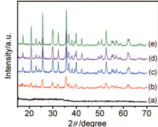
Figure 2. XRD patterns of product obtained at different reaction concentra-tions: (a) 0.1 M, (b) 0.25 M, (c) 0.5 M, (d) 0.75 M, and (e) 1.0 M.
reaction for the formation of LiFePO4 can be carried out above a
certain temperature. Taking crystallinity and cost into consideration, the optimal ratio of DMSO to H2O is 1:1.
Effect of reactant concentration.—When the ratio of DMSO and mixed water solution was fixed at 1:1, the boiling point of the mixed solution reached 108◦C. Fixing the reaction time at 2 h, we can
exam-ine the effect of reactant concentration on the crystallexam-ine structure of the products.
Fig.2shows the XRD patterns of products obtained at different reaction concentrations. It can be seen that when the reactant con-centration of FeSO4 is 0.1 M, the obtained product is completely
amorphous, indicating that the crystallization reaction did not occur at a concentration below 0.1 M. The characteristic diffraction peaks of LiFePO4gradually appear and the intensity of the peaks gradually
increases with increasing reactant concentration. When the reactant concentration of LiFePO4increases to 1 M, the diffraction peaks are
sharp and narrow, indicating that the sample had high crystallinity. Af-ter retrieval, all the diffraction peaks are in full accord with the ordered LiFePO4olivine structure (JCPDS Card no. 40-1499) indexed in the
orthorhombic Pnma space group and show no evidence of impurity phases. Experiments indicated that olivine-structured LiFePO4can be
directly synthesized in a mixture of DMSO and water under ambient pressure and low temperature for a short time. A high concentration is favorable to crystal structure development and improved produc-tion efficiency. Due to the poor solubility of LiOH, a 1 M reactant concentration is identified to be favorable.
Effect of reaction time.—The ratio of DMSO and water solution was fixed at 1:1, and the reactant concentration of FeSO4was fixed
at 1 M. The influence of reaction time on the crystal structure and particle sizes of the product was then examined.
The XRD patterns and SEM images of LiFePO4obtained for
dif-ferent synthesis times are shown in Fig.3a. In each case, the XRD patterns of all samples accord very well with LiFePO4and no
impu-rity phase can be detected. It can be concluded that olivine-structured LiFePO4can be synthesized in a mixture of DMSO and water at 108◦C
in only 1 h. This process can be expressed by the following equation: FeSO4+H3PO4+3LiOH
381K
−→LiFePO4↓ +Li2S O4+3H2O
The key factor in the formation of LiFePO4 using this system
is the boiling point rise caused by DMSO, which can reduce the surface tension of the initial LiFePO4 crystalline nucleus and impel
the reaction toward the formation of LiFePO4. In Figure 3it can
be seen that as the reaction time is prolonged, the crystallinity and particle sizes all gradually increase. The particles are smaller with a 1 h reaction time, but the crystallinity is lower. While the particle size increases significantly after 4 h, this length of time is unfavorable to the intercalation and deintercalation of lithium ions. The LiFePO4
Figure 3. (a) XRD patterns of LiFePO4 obtained with different synthesis
times: (1) 1 h, (2) 2 h, and (3) 4 h, and their corresponding SEM images for (b) 1 h, (c) 2 h, and (d) 4 h.
obtained in 2 h has a well developed crystal structure, small crystals, and a narrow size distribution, so we conclude that 2 h is the best reaction time for preparing LiFePO4.
Effect of sintering time.—Although LiFePO4 with an
olivine-type structure and small grains can be synthesized in a mixed solution of DMSO and H2O in a short time, its electrochemical
performance is unsatisfactory, especially the rate capability. Accord-ing to Delacourt et al.,28 this may be attributable to the presence of Fe3+ in the crystal structure of LiFePO
4 obtained by the
liquid-phase method and the hydrothermal method, which can be expressed as LiFe1−xFexPO4(OH)x, so appropriate heat-treatment is important.
There are two problems to consider in heat-treatment: guaranteeing the purity and crystallinity of samples, and maintaining the particle sizes and size distribution of samples synthesized in the liquid-phase. For this reason, we mixed the as-prepared LiFePO4powder with a
cer-tain amount of glucose and sintered the mixture under a 5% H2–95%
N2atmosphere. Part of the amorphous carbon formed by glucose at a
high temperature is used to reduce Fe3+while the rest coats the
sur-face of the LiFePO4, functioning as a conductor and inhibiting grain
growth.
The crystalline structure and morphology of the LiFePO4/C
pow-ders sintered at 600◦C for 1 h, 3 h, and 5 h can be observed in Fig.4. It
can be seen that as sintering time increases, the crystallinity and par-ticle sizes of the samples increase. The LiFePO4/C sintered at 600◦C
for 3 h has intact, higher diffraction peaks and fine crystals in the range of 80–300 nm with a narrow particle size distribution. Increasing the sintering time to 5 h results in an intact crystalline structure and large particles that prevent the intercalation and deintercalation of lithium ions. Shortening the sintering time to 1 h weakens the intensity of the diffraction peaks too much. Thus, the most feasible sintering time proposed is 3 h.
Effect of sintering temperature.—To determine the optimal sinter-ing temperature, LiFePO4/C was obtained after annealing at 500◦C,
600◦C, and 700◦C for 3 h. XRD patterns and SEM images of
LiFePO4/C obtained at different sintering temperatures are shown
in Fig.5. We can see that the sample calcined at 600◦C has intact,
higher diffraction peaks and fine crystals in the range of 80–300 nm with a narrow particle size distribution. When the sintering tempera-ture is increased to 700◦C, the particle size increases. Reducing the
sintering temperature is favorable for preventing particle growth but
Figure 4. (a) XRD patterns of LiFePO4/C obtained by annealing at 600◦C for
(1) 1 h, (2) 3 h, and (3) 5 h, and their corresponding SEM images for (b) 1 h, (c) 3 h, and (d) 5 h.
unfavorable for crystallinity. Therefore, the trade-off feasible sintering temperature is 600◦C.
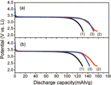
Electrochemical properties.—The electrochemical performance of the synthesized LiFePO4/C depended strongly on the sintering
temperature and time. The optimal LiFePO4/C was sintered at 600◦C
for 3 h, and had a first discharge capacity of 157.7 mAh g−1at 0.2 C,
which is close to 93% of the theoretical capacity (170 mAh g−1). The
initial discharge capacity of LiFePO4/C first increased then decreased
with increasing time (Fig.6a) and temperature (Fig.6b). This result can be attributed to the optimal particle size and crystallinity, which were confirmed by the XRD and SEM patterns.31However, the length of the voltage platform is found to be less than that of sample treated for 5 h. And at the same time, the arc portion at the end of curve is longer. It might be attributed to the formation of defect sites during annealing process according to other reports.32,33As shown in Fig.4a, the XRD patterns of LiFePO4with different sintering times at 600◦C,
Figure 5. (a) XRD patterns of LiFePO4/C obtained by annealing at (1) 500◦C,
(2) 600◦C, and (3) 700◦C for 3 h, and their corresponding SEM images at
A334 Journal of The Electrochemical Society, 159 (4) A331-A335 (2012)
Figure 6. (a) Discharge curves of LiFePO4/C nanocomposites for different
sintering times: (1) 1 h, (2) 3 h, and (3) 5 h; (b) discharge curves of LiFePO4/C
nanocomposites at different sintering temperatures: (1) 500◦C, (2) 600◦C, and
(3) 700◦C.
the crystallinity of sample treated for 5 h is higher than that of sample treated for 3 h. In the meantime, the crystallinity improves with the increase in sintering temperature. According to some references, elec-trodes with low crystallinity might have nanoclusters or defect sites, which make the non-uniform lithiation or delithiation occur during the cycling.32,33This might be the reason of somewhat declining plateau in the sample treated for 3 h.
Figure7shows the initial discharge curves of LiFePO4/C prepared
under optimal conditions between 2.3 and 4.2 V at different rates. The first discharge capacity is 157.7 mAh g−1 at 0.2 C, close to 93% of
the theoretical capacity (170 mAh g−1). Good discharge platforms are
still maintained even at discharge rates of 0.5 C, 1 C, 3 C, and 5 C, with first discharge capacities of 149 mAh g−1, 142.5 mAh g−1, 129.5 mAh
g−1, and 126.5 mAh g−1, respectively. Even at 10 C, the discharge
specific capacity of the product reaches 104 mAh g−1, demonstrating
a good high-rate discharge property. The results indicate significant potential for meeting the requirements of electric vehicles (EVs) and hybrid electric vehicles (HEV).
The cycling behavior of LiFePO4/C prepared under optimal
conditions at room temperature was presented in Figure8. There the capacity retention rate remains above 90% of the initial rate after 200 cycles at 5 C and 10 C. These results demonstrate that the LiFePO4/C
Figure 7. Discharge curves of LiFePO4/C prepared under optimal conditions,
at different rates.
Figure 8. Cycling performance of LiFePO4/C prepared under optimal
condi-tions, tested at room temperature.
nanoparticle cathode materials prepared by the liquid-phase method in this study exhibit excellent discharge capability and good high-rate cycling. Thus, the material’s exceptional electrical properties first arise from the small, uniform LiFePO4/C nanoparticles obtained
by the liquid-phase method, then from carbon encapsulation and spheroidization.
The above experiments show that the particle size of LiFePO4
has a great effect on its charge-discharge capacity, especially its rate capability.16 When the grains are smaller, their surfaces can be effectively improved to increase their contact area with the electrolyte and shorten the lithium ion diffusion channel, which is beneficial for the insertion and extraction of lithium ions.34 Meanwhile, the presence of a small amount of carbon can also increase the material’s conductivity. Zhang35 indicated that LiFePO
4 with a particle size
of 100∼350 nm showed better electrochemical performance at high rates than excessively small LiFePO4(less than 100 nm). The particle
size of our LiFePO4/C composite is in the range of 80∼300 nm,
so the improvement in high rate capability is in accordance with Zhang et al.
Conclusions
In this paper, we firstly synthesized olivine-type LiFePO4 by the
solution-phase method using DMSO as a boiling point raiser and crystal growth inhibitor at low temperature and ambient pressure for a short time, and then sintered the LiFePO4 with a certain amount
of glucose to get LiFePO4/C composite. Through observing the
ef-fects of the solvent to water ratio, reactant concentration, reaction time, and sintering temperature on the crystallinity, morphology, and electrochemical performance of the LiFePO4/C composites, we found
the optimal conditions to be as follows: DMSO:water = 1:1, reactant concentration 1 M, reaction time 2 h, mixed with a certain amount of glucose and sintered at 600◦C under a 5% H
2–95% N2atmosphere for
3 h. The LiFePO4/C composites obtained by this method and
condi-tion deliver smaller, more uniform particles and better electrochemical performance. Electrochemical tests showed that the special capacity of LiFePO4/C composite is 157.7 mAh g−1at a 0.2 C discharge rate,
close to 93% of the theoretical capacity (170 mAh g−1). A special
ca-pacity of 126 mAh/g and 104 mAh/g can be achieved even at 5 C and 10 C, with the material showing no significant capacity fading after 200 cycles. The results demonstrate that the LiFePO4/C composites
synthesized by this method have a high specific capacity and excellent cycling stability and rate capability.
Acknowledgments
This work was financially supported by the Natural Science Foun-dation of China under approval No. 21071046.
References
1. A. K. Padhi, K. S. Nanjundaswamy, and J. B. Goodenough,J. Electrochem. Soc., 144, 1188 (1997).
2. K. F. Hsu, S. Y. Tsaya, and B. J. Hwang,J. Mater. Chem., 14, 2690 (2004). 3. B. F. Wang, Y. L. Qiu, and L. Yang,Electrochem. Commun., 8, 1801 (2006). 4. G. X. Wang, L. Yang, Y. Chen, J. Z. Wang, Steve Bewlay, and H. K. Liu,Electrochim.
Acta, 50 4649 (2005).
5. X. L. Xi, G. L. Chen, Z. R. Nie, S. He, X. Pi, X. G. Zhu, J. J. Zhu, and T. Y. Zuo,
J. Alloys and Compd., 497, 377 (2010).
6. M. R. Roberts, G. Vitins, and J. R. Owen, J. Power Sources, 179, 754 (2008).
7. K. T. Lee and K. S. Lee,Power Sources, 189, 435 (2009).
8. G. R. Hu, X. G. Gao, Z. D. Peng, K. Du, X. Y. Tan, and Y. J. Lin,Trans. Noferrous Met. Soc. China, 17, 296 (2007).
9. Y. Jin, C. P. Yang, X. H. Rui, T. Cheng, and C. H. Chen,Power Sources, 196, 5623 (2011).
10. D. H. Kin and J. Kim,Electrochem. Solid-State Lett., 9, A439 (2006).
11. L. J. Li, X. H. Li, Z. X. Wang, H. J. Guo, L. Wu, Y. Hao, and J. C. Zheng,J. Alloys Compd., 497, 176 (2010).
12. D. Y. Wang, H. Li, S. Q. Shi, X. J. Huang, and L. Q. Chen,Electrochim. Acta, 50, 2955 (2005).
13. C. H. Mi, Y. X. Cao, X. G. Zhang, X. B. Zhao, and H. L. Li,Powder Technol., 181 301 (2008).
14. Y. G. Wang, Y. R. Wang, E. J. Hosono, K. X. Wang, and H. S. Zhou,Angew. Chem. Int. Ed., 47, 7461 (2008).
15. A. Kuwahara, S. Y. Suzuki, and M. Miyayama,Ceram. Int., 34, 863 (2008). 16. M. Gaberscek, R. Dominko, and J. Jamnik, Electrochem. Commun., 9, 2778
(2007).
17. F. Yua,, J. J. Zhang, Y. F. Yang, and G. Z. Song,J. Power Sources, 195, 6873 (2010).
18. Y. Ding, Y. Jiang, F. Xu, J. Yin, H. Ren, Q. Zhuo, Z. Long, and P. Zhang,Electrochem. Commun., 12, 10 (2010).
19. F. Yu, J. J. Zhang, Y. F. Yang, and G. Z. Song,J. Power Sources, 189 794 (2009). 20. J. F. Ni, M. Morishita, Y. Kawabe, M. W. N. Takeichi, and T. Sakai,J. Power Sources,
195, 2877 (2010).
21. E. M. Jin, B. Jin, D. K. Jun, K. H. Park, H. B. Gu, and K. W. Kim,J. Power Sources, 178, 801 (2008).
22. Z. L. Wang, S. R. Su, C. Y. Yu, Y. Chen, and D. G. Xia,J. Power Sources, 184, 633 (2008).
23. A. Aimable, D. Aymes, F. Bernard, and F. LeCras,Solid State Ionics, 180, 861 (2009).
24. D. Rangappa, M. Ichihara, T. Kudo, and I. Honma,J. Power Sources, 194, 1036 (2009).
25. G. C. Liang, L. Wang, X. Q. Ou, X. Zhao, and S. Z. Xu,J. Power Sources, 184, 538 (2008).
26. S. A. Hong, S. J. Kim, J. H. Kim, K. Y. Chung, B. W. Cho, and J. W. Kang,
J. Supercrit. Fluids, 55, 1027 (2011).
27. D. Rangappa, K. Sone, T. Kudo, and I. Honma,J. Power Sources, 195, 6167 (2010). 28. C. Delacourt, P. Poizot, S. Levasseur, and C. Masquelier,Electrochem. Solid-State
Lett., 9, A351 (2006).
29. C. Delacourt, P. Poizot, and C. Masquelier, Crystalline nanometric LiFePO4,
WO/2007/000251.
30. Z. R. Chang, Y. Liu, H. W. Tang, X. Z. Yuan, and H. J. Wang,Electrochem. Solid-State Lett., 14(6), A90 (2011).
31. L. Q. Sun, R. H. Cui, A. F. Jalbout, M. J. Li, X. M. Pan, R. S. Wang, and H. M. Xie,
J. Power Sources, 189, 522 (2009).
32. K. Chang and W. X. Chen,J. Mater Chem, 21, 6251 (2011). 33. K. Chang, W. X. Chen,ACS Nano, 5 4720 (2011).
34. Z. R. Chang, H. J. Lv, H. W. Tang, H. J. Li, X. Z. Yuan, and H. J. Wang,Electrochim. Acta, 54, 4595 (2009).