HAL Id: hal-00470323
https://hal.archives-ouvertes.fr/hal-00470323
Submitted on 6 Apr 2010
HAL is a multi-disciplinary open access
archive for the deposit and dissemination of
sci-entific research documents, whether they are
pub-lished or not. The documents may come from
teaching and research institutions in France or
abroad, or from public or private research centers.
L’archive ouverte pluridisciplinaire HAL, est
destinée au dépôt et à la diffusion de documents
scientifiques de niveau recherche, publiés ou non,
émanant des établissements d’enseignement et de
recherche français ou étrangers, des laboratoires
publics ou privés.
Cross-layered Synchronization Protocol for Wireless
Sensor Networks
Thomas Beluch, Daniela Dragomirescu, Florian Perget, Robert Plana
To cite this version:
Thomas Beluch, Daniela Dragomirescu, Florian Perget, Robert Plana. Cross-layered Synchronization
Protocol for Wireless Sensor Networks. 2010 Ninth International Conference on Networks, Apr 2010,
Les Menuires, France. pp.167-172, �10.1109/ICN.2010.36�. �hal-00470323�
Cross-layered Synchronization Protocol for
Wireless Sensor Networks
Thomas Beluch, Daniela Dragomirescu, Florian Perget, Robert Plana
CNRS ; LAAS ; 7 avenue du colonel Roche, F-31077 Toulouse, France Universit de Toulouse ; UPS, INSA, INP, ISAE ; LAAS ; F-31077 Toulouse, France
Email:{beluch, daniela, perget, plana}@laas.fr
Abstract—The aircraft industry has a conception cycle based on a massive use of Computer Assisted Design in order to allow more complex plane designs, and cheaper development costs compared to multiple prototyping steps. Among the many pro-cesses necessary to validate calculated aerodynamic models, real time pressure measurements are made on the wings during test flights. Such measurements are currently performed using wired sensors, with all the cost and weight problems it causes. Advances in wireless sensor network performances and improvement of attainable bit rates allow research on such measurement systems using Wireless Sensor Networks (WSNs). However, current WSN synchronization protocols do not reach performances required for a reliable correlation of data collected by all the sensors. In this paper, we present a solution to overcome this difficulty to reach sub-microsecond synchronization based on cross-layered design . Specific algorithms are implanted into the MAC and physical layers and form a cross-layered synchronization protocol for deterministic Wireless Sensor Networks named WiDeCS (Wireless Deterministic Clock Synchronization). This protocol propagates master time reference to nodes of a cluster tree network. WiDeCS Cross layered scheme is possible thanks to flag signals in the physical layer. These signals capture precise dates of transmission and reception. Hardware level simulations show a synchronization precision of 100 ns. In this paper, the sources of variable delays in WSN network interfaces are detailed, and the effect of cross-layered WiDeCS scheme on the knowledge of different delays is explained.
Index Terms—synchronization; Wireless Sensor Networks; MAC Layer; cross-layering
I. INTRODUCTION
Recent research has lead to advances in digital circuits, analog and RF design, Micro ElectroMechanical Systems and sensing technologies. These advances have allowed the fabrication of integrated small form-factor embedded systems called nodes. Such systems find their main applications in the field of unobtrusive and remote monitoring when deployed as a sensing and communicating network.
The applications for these sensor networks vary from health monitoring for dependent persons to real time test and mea-surement. Most of these applications require the nodes to preserve a synchronized clock information in order to link each measurement to the specific moment it was taken. However this constraint becomes stronger when it comes to study phenomena with fast variation and large effect areas. During validation of the simulated models, aerodynamic flows are measured during test flights in order to confirm simulations in virtual wind tunnels with real captured data. The information
concerning pressure over and under the wings is then corre-lated to deduct airflows. Such signal processing technique, to be accurate, requires sub-microsecond synchronized sensors.
For many years, high speed wired computer networks have concentrated a large part of the research about time synchronization. Network Time Protocol (NTP) is the widely spread clock synchronization protocol used for synchronizing computers over the internet. For more precise clock synchro-nization, IEEE 1588 also known as Precision Time Protocol (PTP) is used. Performances attained by such protocols can reach synchronization precisions of 100 ns. This protocol, however, uses a large amount of data sent on the network, which will lead to a high power consumption, which is not affordable in Wireless Sensor Networks. Some new protocols have been developed that take into account specific needs for usability in Wireless Sensor Networks. These protocol, mostly lightweight, are based on a small number of synchronization steps. A sync packet can be timestamped when transmitted, thus providing an approximate date to the receiver. Other methods include an handshake in the scheme. However, these protocols are limited by a recurring drawback of the standard network interfaces. The interfaces are mostly non deterministic in terms of latency, and do not allow precise time-stamping of the events. More recently, a device allowing timestamping of frames at a PHY layer has been patented [1]. However, this device requires a full IP stack to work properly, and therefore is not adapted to lightweight WSN.
Our solution is based on a highly cross-layered system. Con-sidering that common synchronization systems at application level are limited by a sum of non determinism at different levels, a solution can be to overcome this non determinism by the means of cross layering and physical level time-stamping. In this case, the only remaining variable is the propagation time through converters, RF frontend and the channel itself. Moreover, for practical issues, this synchronization scheme is implemented jointly to the MAC layer at hardware level. The result of this development is a full hardware transceiver interface containing the physical layer, a MAC layer, and a synchronization scheme.
An overview on related work in clock synchronization is presented in Section II. In Section III, the context is detailed along with corresponding assumptions. The Cross-layered Synchronization protocol for Deterministic Wireless Sensor Networks is explained and the related error analysis
is performed in Section IV. Section V details the simulated testbench and the experimental testbench and shows measured performances.
II. RELATEDWORK
Research on time synchronization has been made for many years, mostly on traditional computer networks. This is due to the importance of synchronization in various domains such as process automation, high precision multi sensor measure-ments, and detection of events which must be dated precisely. A small number of protocols cover most of the requirements for these networks, from Network Time Protocol (NTP), to Precision Time Protocol (PTP) with different performances with respect to their respective applications and objectives in term of network occupation.
In the case of need for high precision synchronization, a standard, IEEE 1588 Precision Time Protocol (PTP), has been proposed for synchronizing wired network interfaces by statistically modeling the entire path between the two computers which must be synchronized. The functioning of this protocol is :
• Offset measurement: The master sends a packet
contain-ing an approximative date of emission. The slave saves the date of reception of this packet. Then the master sends another packet containing the exact date at which the original packet was sent. The clock offset is calculated by substracting this date to the date of reception in the slave.
• Delay measurement: The previous measured values do
not take into account the network link, and therefore they need to be refined. To do so, a delay measurement is performed. This consists in sending a packet from the slave to the master. The master then answers with its reception date, and this date is compared with the original date of emission in the slave.
Although this protocol enables sub-microsecond synchroniza-tion, it uses a large number of packet to reach such perfor-mances. That is why it is not adapted to wireless networks.
More recently, research efforts have been concentrated on Wireless Sensor Networks. The cost of such networks is continuously falling due to the reduction of manufacturing costs. Such networks can cover a wider range of applications than the ones possibles using wired networks. Synchronization protocols for WSN include GPS time synchronization, useful when the nodes are moving, or are rarely in range for transmit-ting data but costly in terms of processing resources. Protocols based on communication between nodes are more widely proposed. The following protocols represent an overview of the published synchronization protocols specific to WSN.
First synchronization protocols which have been presented by Ping et al. [4] were mostly based on a master / slave model. A timestamp is merged in the packet emitted by the master. The slave, on the other hand captures the date at the beginning of the reception. These protocols allow short initial synchronization in the sensor network along with reduced use of the network link. However, it is not easy to
obtain synchronization under 15µs. A similar protocol has been developed by Ganeriwal et al. [3] and provides a more precise clock synchronization owing to bidirectional use of the link. Both the master and the slave send messages including timestamps.
Other protocols allow receivers to be synchronized to each other by the means of a synchronization beacon sent by a master. Synchronization is not guaranteed between the slaves and the master. However, the slaves are synchronized to each other due to similar receivers and propagation times between them. Reference Broadcast Synchronization (RBS) is the most known protocol developed using these techniques. Improved protocols based on RBS have been proposed by PalChaudhuri et al. [5] and Mar´oti et al. [6]. IEEE 1588 PTP and its ability to perform very precise synchronization offset of hundreds of nanoseconds has also been adapted to WLAN networks with success [7], attaining 600 ns clock offsets. However this implementation is not adapted to the field of WSN due to its complexity and its induced power consumption.
Table I summarizes the existing protocols up according to the comparison framework described by Sundararaman et al. [8].
III. CONTEXT ANDASSUMPTIONS
To evaluate a system’s compliance with its specific re-quirements, Hardware System Testing is conducted on the complete and integrated system. This phase is essential in all industry branches, especially in the regulated and critical context of aerospace. In the final phase of the development of an airplane, flight-test equipment gathers and analyzes data during flight to evaluate evolution of parameters of the aircraft and to validate its design, including safety aspects. One of the most critical tests is the measurement of the pressure on the wings during flight. New aircrafts are computer designed with the use of virtual wind tunnels. Accurate measurements have then to be done on the aircraft to validate the model before the actual production. Such systems, intensely used by aircraft manufacturers, currently use wired systems. Sensors, placed on the wings, are wired to a concentrator inside the cabin. Although good performance is observed in terms of measurement accuracy and synchronization, these systems show strong drawbacks. The two most troublesome ones are the weight of the system and its installation. The weight of all the cables passing through the wings modifies its behaviour, and can introduce false errors to the testing process. These cables also represent a challenge during the installation of the measurement setup and increase the cost of installation of such systems. These points and the complexity of such systems do not allow a great number of measurement points. For all these reasons, research is currently conducted [9] on a wireless measurement system based on wireless sensors networks (WSNs) over Ultra Wide Band (UWB) channels.
From the context described before, we can extract required parameters the MAC Layer and Synchronization protocol have to reach.
TABLE I
QUANTITATIVE PERFORMANCE COMPARISON OF SYNCHRONIZATION PROTOCOLS
Protocol Precision Piggybacking Complexity Convergence Time Network size RBS [2] 1.85 ± 1.28µs N/A High N/A 2-20 nodes Ganeriwal et al. [3] 16.9µs No Low Unknown 150-300 nodes
Ping [4] 32µs Yes Low High (multi-hop) Unknown PalChaudhuri et al. [5] U nknown Unknown High N/A Unknown Mar´oti et al. [6] 1.5µs + 5µs / hop No Low N/A 50 - 60 nodes Cooklev et al. (IEEE 1588 over WLAN) [7] 600ns No High N/A 2 nodes (ad-hoc)
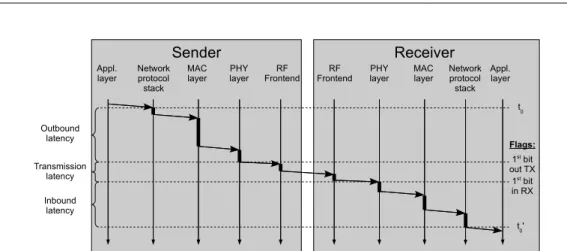
Appl. layer Network protocol stack MAC layer PHY layer RF Frontend Appl. layer Network protocol stack MAC layer PHY layer RF Frontend Sender Receiver Outbound latency Inbound latency Transmission latency t 0 1st bit out TX 1st bit in RX t 0' Flags:
Fig. 1. Latencies involved and flag positioning for WiDeCS
• Continuous emission: Measured data has to be provided
to the data logger continuously. Measurements are taken every few tens of microseconds and sent to the data processing unit.
• Correlation possible in 3D aerodynamic models: A
cor-relation is performed on simultaneously measured data to extract informations about air flows around the plane. To perform such correlation, the exact positioning of every sensor has to be fixed during the development of the calculation tool. This requirement enables a simplification of the whole network which will requires to be pre-defined and fixed through time.
• Precise synchronization of the measurements through the
entire system: This requirement is the reason for the development of the proposed synchronization protocol. In the literature, no proposed protocol allows precise synchronization between measurements from hundreds of sensors with a maximum tolerated offset under the microsecond.
• No available direct power supply: Since the sensing
nodes have to be stuck on a wing, it is impossible to supply power through wires. The nodes then have to be self-powered. To reach this objective, nodes have to be designed with low power elements.
• Tunable sensing parameters: The data processing unit
requires the possibility to act on parameters of the sensing elements.
All these requirements represent a challenge for the de-signer of a synchronization protocol. The proposed protocol described below has to meet all these requirements, while using simple mathematic operations to keep a low power consumption.
IV. WIRELESSDETERMINISTICCLOCK
SYNCHRONIZATION(WIDECS)
The context detailed before adds restrictions to the syn-chronization protocol. The number of these restrictions and their severity requires to develop new very specific MAC layer and synchronization protocol. In the literature, no proposed protocol allows to reach such low offsets while keeping an implementation as simple as possible.
The proposed synchronization protocol takes advantage of the restriction to make strong assumptions and simplify the development of both the MAC layer and the synchronization protocol.
A. General description
The Wireless Deterministic Clock Synchronization
(WiDeCS) protocol is based on the planning of transmissions, and the respect of this planning. It is designed for propagating the master clock of a star network to all the slaves. The cluster tree is organized as stacked levels of star networks named piconets. This protocol then propagates the clock information to slaves of these networks. These slaves then repeat the operation with levels below.
!
" #$ #% #& #' #( #) #* #+ " #+
Fig. 2. Time Division Multiple Access channel occupation
For better results, a Time Division Multiple Access MAC layer is used. This MAC layer divides time in slots attributed to the nodes of the same level in the tree. Figure 2 shows the occupation of the sub-channel used by each piconet. The figure 1 details sources of delays in the network link. Delays are measured on the first effective bit (events linked to preambles and serialization have to be de-embeded). Current synchronization protocols tend to determine these delays by the means of time stamping. Efforts have been made to place this time stamping as close as possible to the effective channel, thus reducing uncertainties on the characterization of the propagation time on the channel. However, none of the known protocols uses time stamping at levels as low as physical (PHY) layer. WiDeCS uses time stamping at the time of the first effective bit at the output of the PHY layer in emission, and the first effective bit in input of the PHY layer in reception. These flags then enable precise measurement of the propagation time except for the jitter linked to RF front-ends. We name these flags TX ONGOINGfor the first bit of effective
data out of the PHY transmitter, and RX ONGOING for the
first bit of effective data entering the PHY receiver. Flagging the first effective bit is harder than flagging any output of data, including preambles. It has one advantage compared to the simpler solution: on the receiving side, it takes some time to detect incoming data. The first bit of the preambles would then be lost in most of the cases, thus reducing the accuracy of the captured date.
Owing to this MAC layer, each node of the network is sup-posed to talk at precise moments. Measuring delays between expected receiving times and actual ones helps determining the clock offset and the propagation time. WiDeCS Synchro-nization protocol uses possibilities relative to time division to determine the clock offset between each node and the master. The figure 3 shows the different informations gathered on different sides, and sent to the slaves by the master. The complete synchronization is based on 2 steps.
Phase 1: Pre-synchronization
This step is performed by every slave when joining the network.
The master (the router) has the same communicating hard-ware the slaves have, along with other network interfaces to communicate with higher levels of hierarchy. The function of the master is to create, and regularly send a preamble for the frames of its piconet. The slaves, when reset, or desynchronized, switch to reception only mode, and wait for the master node to indicate the beginning of the frame. When this message is detected, the slave resets its frame counter to a predefined reset value in order to begin transmitting data in the dedicated slot. When this step is passed, the slave switches
Pream
ble
Master
Slave i
Data
Θ
i= Δt
i- δt
mt
mt'
mt
it'
iδt
mδt
iΔt
mΔt
i Clock offset Clock offsetFig. 3. Exchange of timing information
to phase 2 of the synchronization process. Phase 2: Fine-synchronization
Once pre-synchronized, the nodes have a clock offset of 1 µs compared to the master clock.
This step consists in determining the offset with the greatest precision possible. When the slave is allowed to transmit data, it does it at one precise moment ti of the slot. This date
is coded in the protocol and is known by every slave, and more importantly by the master. Data is sent to the PHY layer
when t = ti and a capture of the timer is done when the
TX ONGOING flag is set. ti is then subtracted to this date,
and the result is stored as δti. Note that small deltas (δ) are
used for delays in transmitted packets, whereas capital deltas (∆) are for delays in received packets
δti= t(TX ONGOINGslave) − ti
The master, on its side, capture the date when RX ONGOING
is set, waits for the packet to be passed through the layers to the applicative part, and deducts ti from the captured date.
The result,∆ti, is then stored and linked to the correct node.
∆ti= t(RX ONGOINGmaster) − ti
When the master slot begins, the master start the transmission of a standard preamble to the TDMA frame, and includes delay informations concerning the slave nodes and measured deltas. The information transmitted is named Θi and is defined as
follows:
Θi= ∆ti+ δtm
∆tm is measured while transmitting the packet and is stored
TX ONGOING rises before the transmission of data to the PHY layer has ended.
δtm= t(TX ONGOINGmaster) − tm
The number of bits used in packets transmitted by the master for the complete set ofΘ depends on the number of bits used for the encoding of each Θ. The higher this number is, the faster the synchronization will be optimal. The slaves, when receiving the message from the master, determine∆tm:
∆tm= t(RX ONGOINGslave) − tm
Considering tp the propagation time almost symmetrical. The
clock offset can be determined with these equations. ∆tclk= t′m− tm
∆tclk= δtm+ tp− ∆tm
for packets from the master node, and ∆tclk= t′i− ti
∆tclk= ∆ti− tp− δti
for packets from the slave node. By adding those two equa-tions, we obtain 2 × ∆tclk= ∆ti− δti+ δtm− ∆tm and then ∆tclk= (∆ti+ δtm) − (δti+ ∆tm) 2 (1) ∆tclk= Θi− (δti+ ∆tm) 2 (2)
The correction offset is applied to the timer, forcing rollback if necessary. Consequences depend on the date chosen to apply this correction, and on the actions other processes clock dependent are performing at this moment.
WiDeCS can be used in every frame to maintain a clock as precisely synchronized as possible for all the length of the measurements. Another possibility is to train the slave with an optimal number of frames, and then turn the reception module in sleep mode for as long as blindness is allowed in the network.
B. Application specific improvements and simplification
Usually, a network is composed of nodes coming and leaving the network. The number of nodes changes with time. In the context described before, the network is planed and parametrized before its deployment. Simplifications are then allowed, without risking uncontrolled behavior. The simplifi-cations used in this paper are listed below, and reasons are given for their existence.
• Fixed number of nodes per piconet and pre-programmed
time slots:
As we explained before, the network architecture is fixed, and planned before deployment of the measurement system. The number of nodes for each piconet is then
a tradeoff between attainable uplink bit rate, desired bit rate, and uplink occupation based on these 2 parameters.
• No jamming between neighboring piconets:
The UWB unlicensed band is divided in sub-bands. The placement of piconets on the surfaces can be designed to avoid jamming between channels. This consideration enables the use of one TDMA master per piconet, and then authorizes the whole developed protocols to work correctly.
• Symmetrical links:
Every node of the network is fabricated using the same hardware. Delays in RF frontends are then similar from one node to another.
C. Error Analysis
The errors relative to WiDeCS protocol can be sorted in two major types :
1) Time sampling errors: WiDeCS massively uses time capture to reach a view as deterministic as possible of the whole system. The major drawback of this is the fact that time sampling is limited by a major element: the clock speed. Indeed, it is impossible to tell precisely the date of a digitally
captured event. Captured values have a ±0.5 clock period
uncertainty. When spreading this to the equations, we obtain
∆(X) the value of uncertainty of X(∆tspl = is the time
sampling uncertainty) ∆(∆tclk) = (∆(∆ti) + ∆(δtm)) + (∆(δti) + ∆(∆tm)) 2 ∆(∆tclk) = 2∆tspl+ 2∆tspl+ 2∆tspl+ 2∆tspl+) 2 ∆(∆tclk) = 4∆tspl (3)
By combining equations (2) and (3), we obtain the complete evaluation of the correction to be applied to the timer.
∆tclk= Θi− (δti+ ∆tm) 2 ± 4∆tspl ∆tclk= Θi− (δti+ ∆tm) 2 ± 2tclk (4)
2) RF front-end asymmetry and evolution of the channel:
The other major source of uncertainty is the asymmetry exist-ing between two RF frontends. Although both RF frontends should share the same hardware, slightly different clock speeds could cause unexpected asymmetry between the propagation time among the nodes.
The other phenomena causing unexpected effects on the propagation time (tp) is a fast evolution of the communication
channel. This evolution is compensated during the next two cycles happening after the evolution. Moreover, considering the context and the requirement for frames of a few tens of microseconds, it seems unlikely that it will cause a failure in synchronization.
V. EXPERIMENTALSETUP ANDRESULTS
A. Sample network architecture
All the simulation and experiments are performed using a reference network architecture for all the tests and measure-ments. The network architecture used for this paper is a star network with one master node, and 8 slave nodes. Clock and timing information are independently generated for each node. The slots to be used by each node in the TDMA frame are manually set using switches.
B. Simulations and results
As explained, WiDeCS is a MAC and PHY layer scheme, and has to be implemented at hardware level. VHDL language was used to implement a network interface including the MAC layer with WiDeCS. Hardware simulations are run on Modelsim VHDL simulator [10]. A model of PHY layer
was developed, including additive signals TX ONGOINGand
RX ONGOING with delay corresponding to real delays mea-sured on our MB-OFDM PHY layer [9]. Each node has its own clock. Clock frequencies are defined individually and are bounded at f±1% where f is the central frequency (125 MHz in our tests). A model of the propagation channel is also taken into account by using different delay propagation times.
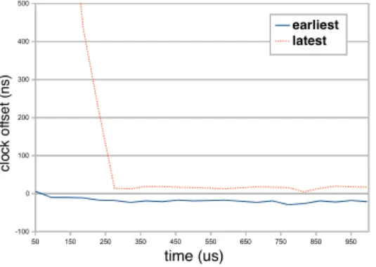
The figure 4 represent the evolution of the clock offset
in the time with WiDeCS enabled at t = 50µs. The offset
measurement is done once per cycle and does not represent a constant offset. The dashed line represent the maximum positive offset a node’s clock could have compared to the master clock at the time of the measurement. The solid line represent the maximum negative offset compared to the master clock at the same time.
50 150 250 350 450 550 650 750 850 950 -100 0 100 200 300 400 500 earliest latest time (us) cl o ck o ff se t (n s)
Fig. 4. Clock offset in slaves vs. time
These results show a stabilization of the offsets at ∆tclk=
±100ns. This is much higher than the performances found in literature, especially for low complexity synchronization pro-tocols for Wireless Sensor Networks. The second interesting result is the convergence time. It takes only 200µs for the WiDeCS protocol to stabilize a synchronized clock.
C. Experiments
The platform contains the implementation of the whole simulated testbench. Every node is implemented on a separate
Spartan3 development board. Each board contains the MAC layer, a hardware implementation of WiDeCS protocol, and an emulated PHY layer. Data is sent to the channel emulator through a FIFO block. The channel emulator is also imple-mented on a Spartan3 board. Implementing all the parts on separate boards guarantees the non interference between the different clocks, and a non biased testbench.
Clock offsets currently measured confirm results from sim-ulations.
VI. CONCLUSION
The WiDeCS protocol for synchronization of Wireless Sen-sor Networks was presented in this paper. It is a synchro-nization protocol for master / slaves architecture in cluster networks. It compares expected vs. real sending and receiving dates, and computes an offset correction which is then loaded into the timer. The fact of including synchronization data in every packet permits to pursue the channel latency’s evolution with a delay of one TDMA frame. Simulated results show synchronization offsets of±100ns, and a convergence time of 200µs. Further ongoing experiments show similar results on FPGA platforms, with one node per FPGA. Our transmitters and receivers are currently being adapted for testing open space performances of WiDeCS. In perspective, we plan to integrate the complete transceiver containing the MAC layer, WiDeCS, PHY layer (MB-OFDM) and the RF frontend into a System On Chip for testing in real conditions, during a plane flight. Future development for WiDeCS protocol will be focusing on the clock drift correction, and on power saving issues and solutions.
ACKNOWLEDGMENT
The authors acknowledge the French Defense Agency (DGA) for funding the doctoral studies of Thomas Beluch.
REFERENCES
[1] S. Defrance, L. Jeanne, and T. Tapie, “Ep1953937 : Clock synchroniza-tion aid device for communicasynchroniza-tion stasynchroniza-tion(s) of a wireless network, and associated clock synchronization device,” Patent, 2008.
[2] J. Elson, L. Girod, and D. Estrin, “Fine-grained network time synchro-nization using reference broadcasts,” SIGOPS Oper. Syst. Rev., vol. 36, no. SI, pp. 147–163, 2002.
[3] S. Ganeriwal, R. Kumar, and M. B. Srivastava, “Timing-sync protocol for sensor networks,” 2003, pp. 138–149.
[4] S. Ping, “Delay measurement time synchronization for wireless sensor networks,” 2003.
[5] S. Palchaudhuri, A. Saha, and D. Johnsin, “Adaptive clock synchroniza-tion in sensor networks,” 2004, pp. 340–348.
[6] M. Mar´oti, B. Kusy, G. Simon, and ´A. L´edeczi, “The flooding time synchronization protocol,” 2004, pp. 39–49.
[7] T. Cooklev, J. Eidson, and A. Pakdaman, “An implementation of ieee 1588 over ieee 802.11b for synchronization of wireless local area network nodes,” Instrumentation and Measurement, IEEE Transactions
on, vol. 56, no. 5, pp. 1632–1639, 2007.
[8] B. Sundararaman, U. Buy, and A. D. Kshemkalyani, “Clock synchro-nization for wireless sensor networks: a survey,” Ad Hoc Networks, vol. 3, no. 3, pp. 281–323, 2005.
[9] J. Henaut, D. Dragomirescu, and R. Plana, “Fpga based high date rate radio interfaces for aerospace wireless sensor systems,” Proceedings of
the 2009 Fourth International . . ., Jan 2009.
[10] M. Graphics, “Modelsim product page,” last visited : 2010/01. [Online]. Available: http://www.model.com