HAL Id: hal-02544384
https://hal.archives-ouvertes.fr/hal-02544384
Submitted on 16 Apr 2020
HAL is a multi-disciplinary open access
archive for the deposit and dissemination of
sci-entific research documents, whether they are
pub-lished or not. The documents may come from
teaching and research institutions in France or
abroad, or from public or private research centers.
L’archive ouverte pluridisciplinaire HAL, est
destinée au dépôt et à la diffusion de documents
scientifiques de niveau recherche, publiés ou non,
émanant des établissements d’enseignement et de
recherche français ou étrangers, des laboratoires
publics ou privés.
IntuiGeo: Interactive tutor for online geometry
problems resolution on pen-based tablets
Omar Krichen, Eric Anquetil, Nathalie Girard
To cite this version:
Omar Krichen, Eric Anquetil, Nathalie Girard. IntuiGeo: Interactive tutor for online geometry
prob-lems resolution on pen-based tablets. European Conference on Artificial Intelligence (ECAI) 2020,
Aug 2020, Santiago de compostela, Spain. pp.1842 - 1849. �hal-02544384�
IntuiGeo: Interactive tutor for online geometry
problems resolution on pen-based tablets
Omar Krichen
and Eric Anquetil
and Nathalie Girard
1Abstract.
This paper presents "IntuiGeo", a tutoring system for ge-ometry learning in middle-schools on pen-based tablets. The objective is to design an intuitive numerical tool which allows the free drawing of geometric shapes by the simulation of the pen and paper traditional setting. Our approach is based on three main principles. The first one is the online recog-nition of the user’s hand-drawn sketches. The second axis of our approach is the ability of the tutor to supervise the resolution strategy of the pupil in the context of a construc-tion problem resoluconstruc-tion. The third principle is the capacity to give real-time visual, corrective and guidance feedback to the pupil to achieve a personalized and autonomous experi-ence. Our system is composed of two main engines. The 2D recognition engine is responsible for the interpretation of the hand-drawn strokes (and has already been validated in [9]). The supervision engine is responsible for the automated gen-eration of a geometry construction problem from a solution example drawn by the teacher, as well as the supervision of the resolution strategies chosen by the pupil. This paper will focus on the concepts associated with the new supervision engine. The first user experiments on the tutor have been conducted in pilot middle-schools in the region of Brittany, France. The analysis of the collected data demonstrates the tutor performance in terms of supervision of the pupils pro-duction and its ability to provide pertinent and personalized corrective and guidance feedback.
1
Introduction
Our work is in the context of the Actif project, which aims at fostering active learning by introducing pen-based tablets in the classrooms. The digital device can be a support to the child’s learning abilities (e.g the Instuiscript project for hand-writing learning [5]). In this paper, we present IntuiGeo, an intelligent tutoring system for learning geometry in middle-school. IntuiGeo’s interface is illustrated in figure 1. Pen and touch interaction allows the free elaboration of geometric shapes, by drawing with the stylus and manipulating virtual tools with the fingers (e.g. compass, ruler, etc). The objective is to provide an intuitive experience for the user, who can draw freely, while our 2D engine, based on bi-dimensional formal-ism, analyses on the fly the stylus input [9]. We are there-fore able to simulate the traditional pen and paper setting,
1 Univ Rennes, CNRS, IRISA,F-35000 Rennes, France, email:
{firstname.lastname}@irisa.fr
Figure 1: IntuiGeo’s interface
making the digital support transparent to the pupil. This al-lows us to overcome the limitations of most dynamic geometry software used in the classrooms, such as Geogebra [2], Cabri-Geometry [10], or Geometer’s SketchPad [16], that require a fastidious training phase for the pupils to get accustomed to the digital support. The tutoring aspect of our system comes from the ability to supervise, in real-time, the pupil’s res-olution strategies in the context of a construction problem, in order to provide correction and guidance feedback. In [4], Chickering and Gamson demonstrate the importance of pro-viding prompt feedback as a principle for good practice in undergraduate education. In [8], Kluger and DeNisi show the impact of feedback intervention on learning performance. To our knowledge, there are no dynamic geometry software that offer the possibility to guide, in real-time, the pupil in his/her resolution steps. We designed a supervision engine that is able to interpret semantically the pupil’s actions relatively to a given problem. The handwritten strokes recognized by the 2D engine are fed in real-time to the supervision engine that will be able to assess the learner knowledge state. We also offer the teacher the possibility to create construction prob-lems by feeding the system with one solution example. From this example, the system should be able to synthesize differ-ent resolution strategies since there are differdiffer-ent ways to solve an exercise. This ability is primordial in order to recognize in real-time the child’s strategy or plan in the context of the reso-lution process. The 2D engine, being already validated in [9], will be presented briefly for clarity purposes. We will focus in this paper on presenting the new supervision engine and the tutoring aspect of our system. We define our supervision engine with three main objectives:
• The automated generation of the construction problem (i.e. exercise) from the example drawn by the teacher;
• Synthesis of strategies to solve the generated exercises; • Supervision of the child resolution to provide feedback.
This paper is organized as follows. Sec. 2 presents an overview of related works on intelligent tutoring systems for geometry learning support. IntuiGeo’s architecture is pre-sented in Sec. 3. The 2D recognition engine and the analy-sis process are explained briefly in Sec. 4. We will focus on the description of the new supervision engine in Sec. 5. To validate this engine, experiments and results are presented in Sec. 6. Conclusion and future works are given in Sec. 7.
2
Related works
Our approach is shaped by two domains, pattern recognition and intelligent tutoring. As mentioned before, our system uses a 2D engine that we designed to recognize and interpret struc-turally, and in real time, the handwritten features. Since this engine has already been validated [9], we will focus in this section on the inner workings of intelligent tutoring systems.
The most common architecture of such systems is the tuple domain module - tutoring module - learner module, alongside the user interface (cf. figure 2). The domain module
encom-Figure 2: The four component architecture [13] passes the domain knowledge, in the form of rules, for exam-ple. The learner module represents the state of knowledge or skills achieved by the student at any given point during the problem resolution. The tutoring module is responsible of the correction and supervision of the chosen strategies.
2.1
Planning and plan recognition for
strategy synthesis
Intelligent tutoring systems vary widely in their architecture [13] [14]. An interesting one is Mentoniezh [15], a tutor for ge-ometry proof demonstrations. The system is divided into two main components: the expert module (by merging domain and tutoring modules, cf. figure 2) and the learner module. The expert module is then responsible for the strategy synthesis while the learner module is responsible for the interpretation and supervision of the pupil resolution strategies. The au-thors consider the strategy synthesis problem as a planning problem [12], such as the goal is to apply a sequence of do-main actions (theorems, facts..) in order to solve the exercise. The knowledge base is an ensemble of if-then rules, repre-senting the geometric axioms and theorems of middle-school level, and the expert module applies this knowledge on a given problem variables to reach a goal state. The strategy synthesis here is offline, such as the expert module generates a set of possible solutions plans for each given problem. The learner module interprets the pupil actions (i.e. demonstration steps) by means of matching the plan/strategy the pupil is choos-ing in real-time with the expert module generated solutions. Recognizing the plan allows feedback generation and student
guidance. The architecture of our supervision engine is inspired by this workalthough our domain, construction of geometric shapes, is different from proof demonstration. Go-ing back to construction problems, in [7], the authors propose a method for synthesizing geometry constructions to solve typical exercises, such as "draw a triangle given the length of its three sides". The authors approach the resolution of such exercises as a program synthesis problem [6], which can be cast as a planning problem. The expert module must then be able to automatically solve the given problem by synthe-sizing construction plans, where the steps are ruler-compass based drawing actions, leading to the construction of the de-sired figure. Our strategy synthesis process is different from the two later approaches in the sense that it is online. Our planning environment is dynamic, i.e. it takes into account exogenous actions. In the context of the resolution of a given problem, our learner module interprets on the fly the pupil’s production relatively to the given instruction (what element of the problem is being drawn?, what are the satisfied con-straints?). Our expert module is then aware of the pupil’s ac-tions in real-time, and tries to find a solution plan that is adapted to his/her resolution strategy. Hence, the tu-tor is able to guide the pupil forwards by hinting to the next possible steps, or backwards if the pupil is stuck.
2.2
Automated generation of construction
problems and knowledge representation
We are interested in works that offer an intuitive author mode for the teacher to create his own construction problems. In [1], the authors propose a method for the automatic generation of geometry proof problems from analyzing a figure uploaded by the user. This enables the teacher to generate a set of sim-ilar exercises from one example. In [17], the authors propose a system for the generation of high-school geometry questions. The user can select a set of concepts from the interface (e.g. triangle + perpendicularity), then the algorithm generates a figure related to these concepts. From this figure, a proof prob-lem is generated. Our approach is more straight-forward: we want the teacher to be able to generate a construction prob-lem from drawing one example solution directly with Intu-iGeo. We choose to represent the information associated to each problem with a knowledge graph [18], containing the ge-ometric objects and the related concepts extracted from the teacher’s drawn solution. This knowledge graph will be used by the expert module to synthesize resolution strategies, or plans, and by the learner module for the semantic interpreta-tion of the pupil resoluinterpreta-tion process. We therefore add a new unit to our system, the problem generation module, for the interactive creation of a new construction problem.Based on this study, we propose an original tutor for the interactive resolution of geometry problems. Unlike most In-telligent Tutoring Systems, IntuiGeo combines two forms of domain knowledge:
• pattern recognition to analyze hand-drawn sketches; • tutoring expertise to create, solve, and correct geometry
construction problems.
This combination allows for the real-time interpretation of the pupil’s hand-drawn strokes as well as his/her resolution strategy, in the context of a free sketching scenario.
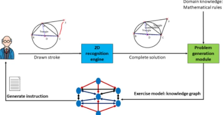
Figure 3: IntuiGeo architecture
3
System architecture
Figure 3 illustrates the architecture of our tutoring system. The combination of the two forms of domain knowledge tran-spires clearly in it as well as in the user-system interaction (cf. figure 4 and figure 5). We present a global vision of the two main engines of IntuiGeo in this section.
3.1
Pattern Recognition expertise
The pattern recognition knowledge is embedded in the 2D engine. It is called that way since it relies on a bi-dimensional formalism CD-CMG [11] (Context Driven Constraints Multi-Set Grammar) to analyze, on the fly, the stylus input, whereas the tutoring expertise is embedded in the supervision engine. The user, a teacher/pupil, can draw freely on the interface, and the stylus input is interpreted, stroke by stroke, by the 2D engine, then transformed into a geometric element by the CD-CMG grammar. A beautification of the raw stroke is per-formed and an "idealized" version of the recognized element is rendered by the interface. The user can implicitly validate this interpretation, or redo his drawing. The 2D engine, along with the user interface, can be thought of as a tool for the free drawing of geometric shapes. This engine is presented in more details in Sec. 4.
3.2
Tutoring expertise
The tutoring aspect of IntuiGeo is represented by the super-vision engine, which is composed of the expert and learner, as well as the problem generation modules.
3.2.1 The problem generation module
Figure 4 illustrates the process of a new construction prob-lem creation. The teacher draws a complete example of the
Figure 4: Teacher interaction with the tutor
target figure or production. The problem generation module takes as input the figure interpreted by the the 2D engine and creates a model of the problem, in the form of a knowl-edge graph, storing all the geometric elements and their links, mathematical constraints such as length, angle, or perpendic-ularity. The knowledge here is defined by the mathematical rules that are applied on the recognized geometric elements. For example, the teacher has drawn a right-angled triangle ABC, the problem generation module will update the K.G. with the link Perpendicular([AB], [AC]). The module trans-lates the knowledge from the graph to plain text to generate the instruction, which can be modified by the teacher.
3.2.2 The learner module
Figure 5 illustrates the child/tutor interaction. The learner module will be responsible of the semantic interpretation of the pupil’s strokes, recognized by the 2D engine. The learner module matches each newly interpreted element with the cor-responding node in the knowledge graph. Hence the extrac-tion of satisfied and unsatisfied constraints is straight for-ward. This enables the tutor to generate corrective feedback. To generate guidance feedback, the learner module communi-cates with the expert module, which will try to synthesize a resolution strategy based on the state of the knowledge graph, that is to say the expert module tries to recognize the solution plan in which the child’s strategy lies.
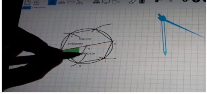
Figure 5: Pupil interaction with the tutor
3.2.3 The expert module
Since all the necessary information about the problem is rep-resented in the K.G. (Knowledge Graph), it is possible to generate alternative strategies to solve an exercise, if we con-sider the problem as a planning problem, where the initial state is an empty drawing zone, and where the final state is a production/figure where all the mathematical constraints in the links of the K.G. are satisfied. The knowledge here is defined by the set of domain drawing actions that will be the basis of the strategy chosen to solve the problem. More details will be given in Sec. 5.
4
The 2D engine
In this section, we present the 2D engine, defined by the CD-CMG grammar [11] and its associated parser.
Definition 1. A CD-CMG is a tuple G=(VN, VT, S, P) with:
• VN: the set of non terminal symbols = symbol classes;
• VT: the alphabet, here VT= {stroke};
• S: the first symbol, or axiom; • P: the set of production rules.
And where a production rule p ∈ P is denoted as follows: α → β Preconditions Constraints Postconditions |α ∈ VN+, β ∈ (VT ∪ VN)+
Where preconditions and postconditions are based on the con-cept of Document Structural Context (DSC), which models a zone in the document and the awaited elements in it. Definition 2. A DSC is defined by (λ)[position](γ)[part] where:
• λ is a set of reference elements;
• position is a zone (i.e. a position) related to λ; • γ is a set of awaited symbols in this zone; • part is a part of the awaited symbol in the zone.
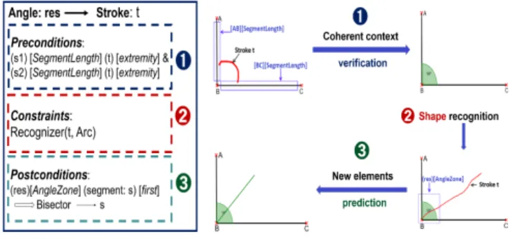
Figure 6 presents the angle production rule. Figure 7 illustrates the roles of the preconditions, postconditions, and constraints blocks. The analysis here is driven by the context. The preconditions, 1 , are a set of DSC that model the verification step of the analysis. In this example, the analyzer checks that the two extremities of the stroke t intersect two existing segments zones (SegmentLength) before checking the constraints block 2 . Here, a shape recognizer is called to verify that t is an arc. The postconditions, 3 , are new DSC, or zones, created after the rule reduction that update the document global structure and model the prediction phase. In this example, the production rule of a bisector will be triggered if a segment intersect the new zone [res] [AngleZone]. Based on these definitions, a bi-dimensional analysis pro-cess is defined, that is a combination of a bottom-up strategy (guided by the reduced elements) and a top-down strategy (guided by the postconditions DSCs). For each new element, the parser searches the DSC it satisfies and vice versa. A pro-duction is triggered if at least one of its preconditions DSC is satisfied and one of its parameters is a new element. The analysis process of a stroke t is illustrated in figure 8. The root represents the stroke t. The nodes and the leaves rep-resent the triggered rules. The analysis result is a sequence of reduced productions rules (blue dotted path). The adapted grammar and the associated parser define our 2D engine. This
Figure 6: CD-CMG rule Figure 7: Blocks role
Stroke (t) Segment (s4) Angle Circle Polygon(pf) Point Triangle Quadrilateral Parallelogram Trapezes Rhombus Rectangle
Figure 8: Analysis tree
enables a real-time interaction with user by the interpretation of the handwritten stroke with visual feedback. This engine has been validated in [9], where more details can be found. In the next section, we present the supervision engine, which constitutes the core of this paper.
5
The supervision engine
As explained in the previous section, the challenges here are the automated generation of construction problems from the teacher’s interpreted strokes, and the supervision of the child’s resolution strategies. In this section, we describe in detail the three modules of this engine and their relations.
5.1
The problem generation module
This module is responsible for the exercise creation and knowl-edge graph (K.G.) construction. Once a complete solution ample is drawn by the teacher, the module generates the ex-ercise model.
Definition 3. The knowledge graph is defined by a set of nodes and edges such as:
• a node n is defined by
– T: the recognized element from the 2D engine; – RefC: reflexive constraints on T, such as length value; – DefC: Constraints depending on the mathematical definition
of T.
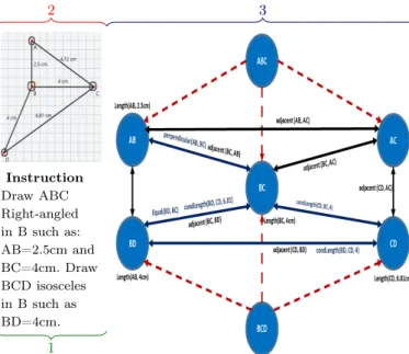
• Each edge is denoted by a triple e = (Nf,Ns,Rel) with – Nf: the node corresponding to the tail node; – Ns: the node corresponding to the head node; – Rel: the set of relative constraints linking Ns and Nf. DefC are directly extracted from the mathematical rules inherent to the geometry domain knowledge. The state of a node, and the state of the K.G. by extrapolation, are defined by the state of the constraints of each node. A node is in the state complete if all of its constraints are satisfied. By con-trast, it is in the state partial if the corresponding geometric element T has been drawn and at least one of its constraints is not yet satisfied. It is then clear that for the exercise to be solved, all the nodes in the K.G. have to be in the state completed. A node is in the idle state if its corresponding el-ement is not yet drawn by the pupil. Figure 9 illustrates the process of knowledge graph construction. In this example, the teacher draws two triangles ABC and BCD (see 2. in figure 9). First, the problem generation module constructs the nodes corresponding to the geometric elements present in the docu-ment. The refC constraints are intrinsic to these nodes (e.g. length(AB,2.5cm)).
Instruction Draw ABC Right-angled in B such as: AB=2.5cm and BC=4cm. Draw BCD isosceles in B such as BD=4cm. 2 1 3
Figure 9:Instruction,Drawn solution,K.G. construction The logical dependence relations are then added (red arrows in figure 9). These dependence relations enable the module to propagate the DefC constraints from a node to its neigh-bours. For example, BCD isosceles =⇒ Equal(BC,BD). Finally, the structural constraints are extracted from the 2D engine, constraints such as adjacency, intersection, that do not depend on a particular figure definition (see 3. in figure 9). Once all this knowledge of the problem is extracted, the generation of the instruction is straight-forward. The prob-lem generation module extracts the necessary and sufficient information from the K.G. to construct the target figure, and translates it to plain text (see 1. in figure 9).
5.2
The learner module
The learner module function is to interpret semantically the pupil’s actions relatively to the resolution of a geometry con-struction problem. Each stroke, transformed by the 2D en-gine in real-time into a new geometric element, is fed into the learner module to assess the resolution state of the pupil.
5.2.1 Verification and corrective feedback
One basic and necessary function of this module is the verifi-cation of the goodness of the pupil’s actions. For example, as in the pen/paper setting, the user draws a segment and labels the extremities as point A and point B. The module will sim-ply search the node in K.G. labelled AB, and replace its ele-ment T by the newly drawn segele-ment. The corrective feedback is then straight-forward, since it is a description of the unsat-isfied and satunsat-isfied constraints in the K.G. node. In our case, we want to go a step further to fluidify the human-machine interaction by establishing the semantic interpretation of the pupil’s actions.
5.2.2 Semantic interpretation and matching
Since we are in a free drawing scenario, pupils are not inclined to label their elements each time they draw them. They can
draw a whole figure without naming their points, and add the labels after figure completion, which render the real-time verification obsolete. Therefore, in order to provide feedback on the fly, the module needs to interpret in real-time what the child intended to draw, by trying to match the new element with one of the nodes of the Knowledge Graph. This is an interesting and important challenge. To do so, the learner module evaluates the adequacy of the new element with each node of the K.G. and chooses the one with the highest score. Figure 10 presents a step in the resolution of the exercise created in figure 9. The node BC has been already solved by the pupil, since the only constraint to satisfy at that point was the length of BC. The pupil draws a new segment denoted s1. The module computes the adequacy score (Adeq) depending on the satisfied constraints of each node as follows.
Definition 4. Adeq(s1, n)= 0, if class(n) 6= class(s1) 0, if |Strutsat(s1, n)| = 0
|Strutsat(s1, n)|+|Semsat(s1, n)|
|Strut(n)|+|Sem(n)| , otherwise
such as Strut is the set of structural constraints for the node n, Sem is the set of mathematical/semantic constraints for the node n, and Strutsat(s1, n) is the set of satisfied structural
constraints when matching s1 with the node n.
Figure 10: Supervision and matching
We can see in figure 10 an unknown extremity label (? in the figure). When evaluating the adequacy of the new segment s1 with a node, the learner module matches s1 with the node label (e.g. ? is labelled A if we are evaluating Adeq(s1, AB)). The node with the highest adequacy score is chosen and the K.G. is updated by replacing the element corresponding to the node by the newly created segment s1 and updating its state with the satisfied and unsatisfied constraints. In this example, the match is the node AB since s1 satisfies two of the three constraints of the node (minus AB⊥BC). Af-ter the matching, the corrective feedback is provided to the pupil. The guidance feedback is the responsibility of the ex-pert module. This automated semantic interpretation allows for an efficient pen-based Human Machine Interaction.
5.3
The expert module
In order to supervise the pupil’s resolution strategies, the tu-tor must have the necessary geometry domain knowledge to solve automatically these construction problems.
5.3.1 Planning domain definition
As mentioned before in Sec.2, a construction problem can be seen as automatic planning problem, where the goal is to
generate a sequence of drawing actions to achieve the target figure. Our approach consists in decomposing the resolution of a construction exercise into an ensemble of sub-problems, such as the resolution of one node is in itself a planning prob-lem. We define our planning environment relatively to each node in the Knowledge Graph. The actions of the pupil (in-terpreted by the learner module) are seen as exogenous events impacting the planning environment of the expert module, which makes it dynamic. More formally, the definition of this state-transition system is as follows:
Definition 5. Our planning domain is a tuple σ=(S, A, E, γ) with:
• S={idle, partial, complete}: the set of states for each node in the K.G.;
• A: the set of drawing actions, defining the behaviour of the ex-pert module;
• E: the set of events observed by the learner module;
• γ=S × (A ∪ E) → 2S a state transition function. If a ∈ A is
applicable then the system is in the state s’=γ(s,a).
The set of actions are mainly ruler-compass based actions, with the possibility of using the protractor to create angles or the try-square tool. Editions actions are also available for the expert module, as well as for the pupil, such as modifying the length of a segment, or the value of an angle.
Definition 6. The actions in our planning domain are defined by a tuple a=(parameters, precond, stroke, effects) where: • parameters are geometric elements or numeric values; • stroke is the drawing action performed on the document; • preconditions and effects are a set of constraints.
An example of such actions is as follows.
Action: MakePerpendicular (Segment: S1, Segment: S2) • precond: Adjacent(S1, S2);
• stroke: OrthoGesture(S1,S2); • effects: Perpendicular(S1,S2).
Here precond are the set of constraints that have to be sat-isfied in the state s in order for the actions to be applicable. Stroke is command gesture realized by the expert on the drawing zone (cf. figure 11, 12). The effects are the con-straints that will be satisfied in the state s’ after the action is realized. The state transition function γ is then defined as: γ(s,a) = s ∪ effects(a).
5.3.2 Planning algorithm
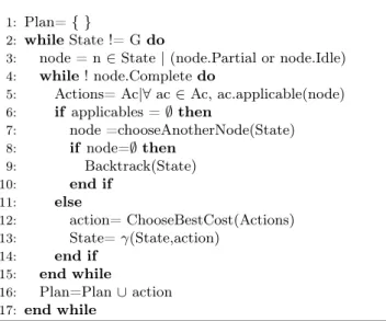
The planning algorithm is necessary to deliver the correction and guidance to the pupil. The objective is to achieve a goal state G where all the nodes of K.G. are in the state Complete. Algorithm 1 illustrates this process. The basic principle is that the expert module tries to solve each node on its own. A node is chosen such as its state is not complete. Then the expert searches for the set of applicable actions on this particular node (line 5 in algorithm 1). If the set of applicable actions is
Figure 11: Orthogonal sign Figure 12: Action result
Algorithm 1Resolution algorithm
Require: State = State of K.G., G=Goal state 1: Plan= { }
2: whileState != G do
3: node = n ∈ State | (node.Partial or node.Idle) 4: while! node.Complete do
5: Actions= Ac|∀ ac ∈ Ac, ac.applicable(node) 6: if applicables = ∅ then 7: node =chooseAnotherNode(State) 8: if node=∅ then 9: Backtrack(State) 10: end if 11: else 12: action= ChooseBestCost(Actions) 13: State= γ(State,action) 14: end if 15: end while 16: Plan=Plan ∪ action 17: end while
empty, the node is not solvable at this point and the expert delays its resolution by choosing another one to solve (line 7 in Algorithm 1). For example, we can’t draw the hypotenuse [AC] without knowing its length (exercise in figure 9). We should solve the other sides of the triangle first. If there is no more solvable nodes (line 8), we are in an unsolvable state, the expert has then to backtrack to the last state, by undoing the last performed action. This feature is necessary, since it mimes the ability of the pupil to erase an error if it exists. If there are applicable actions for the node n, the best action is chosen in terms of cost (line 12). The cost of an action is as follows.
Cost(a) = |effects(a)| - effort(a), where effort is the number of drawing operations needed to execute a. For example, we can consider that the effort of drawing a 60 degree angle with the protractor tool is less than the effort by drawing it by intersecting two compass arcs. The process is repeated until the node is in the state completed. Once it is completed, we repeat the search for another node to solve until all nodes are in the state complete, which means the goal state G is achieved.
With this expert knowledge, the tutor will be able to guide the pupil forwards, with a hint on how to solve the next steps, as well as backwards, with a hint to undo the last ac-tions that led him/her to a deadlock. The experiments demon-strating the performance of the tutor are given in the next section.
6
Experiments and results
IntuiGeo was tested in five pilot middle-schools in the re-gion of Brittany, France. The experiments were conducted by our partners in ergonomics and cognitive psychology from the LP3C laboratory2. We analyze in this section the
perfor-mance of the learner module(is the tutor able to analyze the pupil productions relatively to the instruction?), as well as the performance of the expert module (is the tutor able to find solutions plans given any learner state?). 54 pupils
were given four exercises with increasing difficulty as follows: 1) Draw a rectangle ABCD given AB=4cm and BC=9cm; 2) Draw a parallelogram EFGH given EF=4.5cm,
FG=6.5cm, and EFG=76°;
3) Draw a rhombus ABCD given AB=4cm and AC=7cm; 4) Draw three triangles such as ABC is equilateral, ABD isosceles, ADE equilateral.
For pedagogical purposes, corrective and guidance feedback are given at the pupil’s demand to avoid interference with his/her creative process. Since every action is saved in real-time by the system, we are able to replay exactly, step by the step, the pupil resolution process and feed it to the tutor in a batch fashion. This deployment in the schools had as a re-sult the total of 206 "digital sheets" containing all the saved pupils actions (.e.g handwritten strokes, virtual tools usage) when solving one of the given exercises. This represents the test set we use to analyze our system performance.
6.1
The learner module performance
Let’s note first that the set is unevenly distributed. This is due to the fact that two versions of the same problem were presented to the pupils in the case of the rectangle and the parallelogram, with a change in the angles values and seg-ments lengths. Only the pupils who had the time to complete these two problems were able to try to solve the triangle and rhombus problems. TABLE 1 presents the supervision perfor-mance on each exercise and on the whole set.
Table 1: Learner module performance
Problem Success Failure TP FN Pre Rec Acc
Rectangle 55 20 55 0 100% 100% 100%
Parallelogram 23 71 23 1 100% 95.65% 98.94%
Rhombus 5 19 5 1 100% 83.3% 95.8%
Triangle 3 10 3 0 100% 100% 100%
Total 86 120 86 2 100% 97.72% 99.03%
The objective here is to see if the learner module repre-sented correctly the state of pupil resolution process: success means the tutor considers that the exercise has been solved by the pupil, failure otherwise. (FN) refers to false negatives, productions that were correct but labelled wrongly by the sys-tem as failure. We can observe that Precision (Pre) is 100%, which means the learner module doesn’t take risks in assess-ing the pupil production. However, we can see the presence of 2 false negatives (FN) in the set of 120 negatives (one in the parallelogram set, one in the rhombus set). These FN come from correct strategies that were unknown to the learner module. This will be fixed by enriching the knowledge base of the tutor (e.g. expanding the mathematical knowledge in the DefC constraints and adding new planning domain ac-tions). In any ways, an accuracy (Acc) of 99.03% and a recall (Rec) of 97.72% on a statistically significant set can be con-sidered as an acceptable performance, although there is room for improvement.
6.2
The expert module performance
In order to give pertinent and personalized real-time guidance, the expert module should be able to solve the problem at any given learner state. If the state is not solvable, the expert should be able to backtrack to the last solvable state
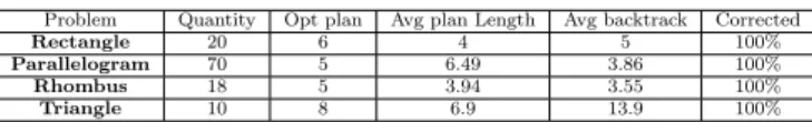
attained by the pupil, and propose a solution plan from there. TABLE 2 presents the expert performance on each ex-ercise and on the set of true negatives. Opt plan illustrates the
Table 2: Expert module performance
Problem Quantity Opt plan Avg plan Length Avg backtrack Corrected
Rectangle 20 6 4 5 100%
Parallelogram 70 5 6.49 3.86 100%
Rhombus 18 5 3.94 3.55 100%
Triangle 10 8 6.9 13.9 100%
optimal plan length chosen by the expert module to solve each of the exercises from the initial state (empty drawing zone). Avg plan length and Avg backtrack represent respectively the average length of the correction plan and the average number of backtracking actions performed by the expert module on the "resolution sheets". The expert module was able to pro-vide a correction plan for each data of the set (Corrected). This demonstrates that it is always able to find a solution plan, given any learner state, either by direct planning if it is solvable, or by by backtracking to the last solvable learner state. The difference between the optimal plan length and the average correction plan length demonstrates on the other hand that the tutor resolution is adaptive to the child pro-duction, and doesn’t simply backtrack to the initial state and plan from there. This result is quite important, since we need IntuiGeo to provide pertinent and personalized guidance. The fact that the system is able to detect the last solvable state is also interesting, since it could avoid error propagation for the pupils.
6.3
Pupils perception and feedback
To see the pupils perception of the tool, and to study its usability, our partners in experimental psychology have con-ducted a post-test questionnaire. After the experiment, the pupils answered these following questions, illustrated in TA-BLE 3, with a Likert scale [3] from one to seven. The
enjoy-Table 3: Post-test questionnaire results
Question Mean Standard deviation Is the tool easy to use? 5,85 1,43
Is the tool useful? 4,7 1,4 Is the tool enjoyable? 5,87 1,27
ment aspect can be easily explained by the digital support (using a tablet is fun). The fact that the system is easy to use and seen as useful by pupils are also interesting aspects: they show that there is a potential for the tutor to help the pupils enhancing their performances. The evaluation of this poten-tial will be studied in future experiments. More details on the project as a whole, as well as an illustrative video demonstrat-ing the user-tutor interaction, can be found on the IntuiDoc team website3.
7
Conclusion
In this paper, we propose IntuiGeo, an interactive geometry tutor on pen-based tablets. The combination of pattern recog-nition with tutoring knowledge allows for our system to be
quite intuitive. In fact, the teacher only needs to draw one ex-ample solution for the tutor to be able to generate the problem model (K.G.), and synthesize alternative resolution strategies. Our learner module interprets in real-time the pupil’s actions and assesses his/her knowledge state, allowing an efficient in-teraction. Our new dynamic planning environment enables the expert module to synthesize strategies in an online fash-ion, which results in a dynamic and personalized corrective feedback. The experiments showed the ability of our tutor to supervise and guide pupils in the resolution process by syn-thesizing resolution plans given any learner state. Our future works consist in the improvement of the tutor’s knowledge base to include more strategies, as well as a wider variety of construction problems. Another axis will be the study of the pedagogical impact of the tutor on pupils performance, with further experiments that will be conducted in middle-schools.
Acknowledgment
"ACTIF" is funded by the region of Brittany and the French state call for projects e-FRAN, operated by the "Caisse des Dépôts". The project is supported by the LabCom « Scrip-tAndLabs » (n° ANR-16-LVC2-0008-01). We would like to tank the partners from the LP3C laboratory who conducted the experiments, as well as the academic partners who par-ticipated in them.
REFERENCES
[1] Chris Alvin, Sumit Gulwani, Rupak Majumdar, and Supratik Mukhopadhyay, ‘Synthesis of geometry proof problems’, in AAAI’14 Proceedings of the Twenty-Eighth AAAI Confer-ence on Artificial IntelligConfer-ence, pp. 245–252. Association for the Advancement of Artificial Intelligence (AAAI), (July 2014).
[2] Kaushal Kumar Bhagat and Chun-Yen Chang, ‘Incorporating geogebra into geometry learning-a lesson from india’, Eurasia Journal of Mathematics, Science and Technology Education, 11(1), 77–86, (2015).
[3] James Dean Brown, ‘Likert items and scales of measure-ment?’, Shiken Research Bulletin: JALT Testing Evaluation SIG Newsletter, 15(1), 10–14, (2011).
[4] Arthur W. Chickering and Zelda F. Gamson, ‘Lifting the cur-tain: The evolution of the geometer’s sketchpad’, AAHE Bul-letin, 39(7), 3–7, (1987).
[5] Nathalie Girard, Damien Simonnet, and Eric Anquetil, ‘Intu-iScript a new digital notebook for learning writing in elemen-tary schools: 1st observations’, in 18th International Grapho-nomics Society Conference (IGS2017), Proceedings of IGS 2017, pp. 201–204, Gaeta, Italy, (June 2017).
[6] Sumit Gulwani, ‘Dimensions in program synthesis’, in Pro-ceedings of the 12th International ACM SIGPLAN Sympo-sium on Principles and Practice of Declarative Programming, PPDP ’10, pp. 13–24, New York, NY, USA, (2010). ACM. [7] Sumit Gulwani, Vijay Anand Korthikanti, and Ashish
Ti-wari, ‘Synthesizing geometry constructions’, SIGPLAN Not., 46(6), 50–61, (June 2011).
[8] Avraham N. Kluger and Angelo Denisi, ‘The effects of feed-back interventions on performance: A historical review, a meta-analysis, and a preliminary feedback intervention the-ory’, Psychological Bulletin, 254–284, (1996).
[9] Omar Krichen, Nathalie Girard, Éric Anquetil, Simon Cor-bille, and Mickaël Renault, ‘Real-time interpretation of hand-drawn sketches with extended hierarchical bi-dimensional grammar’, in 16th International Conference on Frontiers in Handwriting Recognition, ICFHR 2018, Niagara Falls, NY, USA, August 5-8, 2018, pp. 273–278, (2018).
[10] Colette Laborde, ‘Integration of technology in the design of geometry tasks with cabri-geometry’, I. J. Computers for Math. Learning, 6(3), 283–317, (2002).
[11] Sébastien Macé and Eric Anquetil, ‘Eager interpretation of on-line hand-drawn structured documents: The dali method-ology’, Pattern Recognition, 42(12), 3202 – 3214, (2009). New Frontiers in Handwriting Recognition.
[12] John McCarthy and Patrick J. Hayes, ‘Some philosophical problems from the standpoint of artificial intelligence’, in Ma-chine Intelligence 4, eds., B. Meltzer and D. Michie, 463–502, Edinburgh University Press, (1969). reprinted in McC90. [13] Roger Nkambou, Jacqueline Bourdeau, and Riichiro
Mi-zoguchi, Introduction: What Are Intelligent Tutoring Sys-tems, and Why This Book?, 1–12, Springer Berlin Heidelberg, Berlin, Heidelberg, 2010.
[14] Hyacinth S. Nwana, ‘Intelligent tutoring systems: an overview’, Artificial Intelligence Review, 4(4), 251–277, (Dec 1990).
[15] Dominique Py. Environnements interactifs d’apprentissage et démonstration en géométrie, 2001. Habilitation à diriger des recherches de l’université de Rennes I, juillet 2001.
[16] Daniel Scher, ‘Lifting the curtain: The evolution of the ge-ometer’s sketchpad’, The mathematics Educator, 10(2), 42– 48, (2000).
[17] Rahul Singhal, Martin Henz, and Kevin McGee, ‘Automated generation of high school geometric questions involving im-plicit construction’, in Proceedings of the 6th International Conference on Computer Supported Education - Volume 1, CSEDU 2014, pp. 467–472, Portugal, (2014).
[18] Jihong Yan, Chengyu Wang, Wenliang Cheng, Ming Gao, and Aoying Zhou, ‘A retrospective of knowledge graphs’, Frontiers of Computer Science, 12(1), 55–74, (Feb 2018).
![Figure 2 : The four component architecture [13]](https://thumb-eu.123doks.com/thumbv2/123doknet/12508562.340924/3.892.102.394.445.572/figure-the-four-component-architecture.webp)