Automated Support for Experimental Approaches
in Daylighting Performances Assessment
by
Dean M. Ljubicic
Submitted to the Department of Mechanical Engineering In Partial Fulfillment of the Requirements for the Degree of
Bachelor of Science in Mechanical Engineering at the
MASSACHUSETTS INSTITUTE OF TEHNOLOGY October 2005
The author hereby grants to MIT permission to reproduce and to distribute publicly paper and electronic copies of this thesis document in whole or part
Signature of Author
Departnment of Mech(iHl Engineering C Otober 6, 2005
A
Certified by
Accepted by
Professor Marilyne Andersen Thesis Supervisor
Drrfnccn-r Ihn WI I inrrnhrr4 \/ Chairman of the
I In IU7ot.I UJI III I . I IIICI . V
Undergraduate Thesis Committee
ARCHIVES
MASSACHU~tffS- INs-T1 TUTE
Automated Support for Experimental Approaches in Daylighting Performances Assessment
by
Dean M. Ljubicic
Submitted to the Department of Mechanical Engineering In Partial Fulfillment of the Requirements for the Degree of
Bachelor of Science in Mechanical Engineering ABSTRACT
The study of daylight and solar reflection has been a topic of increasing interest over the past two decades. A novel mechanical support has been constructed to help better understand this topic that consists of a five foot in diameter circular table driven to rotate and tilt by computer controlled motors. The first use of this machine is to conduct shadow studies on architectural models. Using the tilt and rotation axis concurrently, a model can be rotated through a path that emulates the sun throughout the course of a day. The second use of the machine is to measure the solar flux emitted from and transmitted
through a sample at different angles of incidence. An elliptical shell will be cut in half and secured to the table with focal points A and B. The incoming light will shine on or
through the sample placed at focal point A, bounce off of the reflective inside of the shell,
then be redirected into a camera placed at focal point B. Two cameras will be used to
measure the visible and infrared spectra of the reflected light. Thesis Supervisor: Marilyne Andersen
Table of Contents
Page #
I. Introduction 4
II. Project Foundations 4
III. Functional Requirements 5
IV. The First Design 6
V. Suspension of the Table 6
A. Ball Bearing Rollers B. Spur Gears
VI. The Table 10
A. Unistrut Backbone
B. Honeycomb Aluminum Base
C. Nylon Gears
D. Steel Track E. Sample Holder
VII. The Frame 14
A. Pillow Block Bearings
B. Slip Ring C. Counterweights
VIII. Power and Movement 15
A. Motors and Gear trains B. Encoders
C. Power Supplies
IX. Discussion 17
X. Conclusion 19
I. Introduction
In the field of architecture, a focus on new lighting and fenestration systems has
developed. New strategies to capture light energy can reduce the power required to heat and cool structures. Better indoor lighting improves the visual environment inside
buildings and can increase productivity as well as enhance comfort levels. By studying shadows cast by models, architects and builders can find the optimal location, design, and orientation of new structures. Thus, to optimize these parameters, it has become a
priority to better understand how light reacts with different surfaces and objects. Many studies have shown vast potential to improve savings and comfort on
current lighting systems with better lighting management. Today, 30% to 40% of power use in non residential buildings is consumed by lighting.' By using enhanced day lighting systems, researchers estimate that this power requirement can be lowered
between 20% to 80%.2 In other studies, it was found in a survey conducted with 20,000
students from California, Massachusetts, and Colorado that students who took
standardized tests in rooms with natural light saw a 26% improvement to their scores.3 Similarly, tests focused on retail outlets that stressed natural lighting showed not only
increase in sales of 30% to 40% and also a 38% reduction of lighting costs.4 These studies highlight only some of the advantages that can be achieved through better
daylight systems.
With such a market for improvement, much research has already been done to improve day lighting systems. Some consumer products, such as new solar blinds and coatings, have been developed to capture and redirect natural sunlight. Yet, many of the optical properties of these systems are still unknown. For example, the reflection from these coatings has been measured with direct head-on light, but not from other incoming angles. A testing device that is capable of varying such angles in a time-efficient manner will further research on this topic. This equipment, that will be called Heliodome, will also emulate the sun's path on an object throughout a day to conduct shadow studies on a
variety of models.
This paper summarizes the design process and manufacturing of the Heliodome's
rotating table. First, the original requirements and specifications are presented. The
construction of this table is then split into four functionally different sections with each
section explained individually. This section houses much of the reasoning and
calculations that were used to make design decisions. Lastly, an overall evaluation of the
Heliodome platform is included, highlighting the things that were done well as well as the things that could have been done better.
II. Project Foundations
The Heliodome is a combination of two research projects packaged into one device. The first of its two primary modes is to function as a heliodon, or a machine used to hold and rotate a model for shadow study purposes. The design of the Heliodome was influenced by one of the only fully automated heliodons in the world, developed in LESO. The second mode functions as a goniophotometer, or an instrument used to
measure light flux from and light transmission through samples. This part of the design was influenced by research published in Solar Energy Materials and Solar Cells.5 This
device also sets itself apart by using an ellipsoidal shell to reflect light instead of a
hemispherical shell, as seen in work published in Computer Graphics.6 The final product, although uniquely designed, fuses together concepts from both these projects to serve
both purposes at once.
III. Functional Requirements
The most basic specification required the Heliodome table to be flat and rotate with computer control on two axis. Additionally, there needed to be an unobstructed path from both sides of the table for the incident light to shine upon or through sample. Below
are the original requirements and figures defined at the beginning of the project.
* The horizontal rotation axis (tilt angle) must allow a 180°range with precision of 0.5°
or better. The full 180°tour should be completed in five seconds time.
* The vertical rotation axis (rotation angle) must allow a 360° range with precision of 1°
or better. The full 360°tour should be completed in ten seconds time.
* The table must be 1.5 meters in diameter to accommodate models up to 1 x 1 x 0.6 meters. There must be access from below to the "central" focal point as well as easily
installed camera and fish-eye lens that does not hinder rotation.
* The rotations of the support must be computer-driven, reliable and precise, without vibrations or unbalance; security components and emergency stops are needed to ensure safe movements.
* The maximal load is not determined precisely, but should not exceed 400 Newtons. * The conversion between the two modes should be made as easily as possible.
* The supporting disk must be designed so that the horizontal rotation axis passes through
the sample face plane and the vertical rotation axis passes through the sample center.
* No hardware can hinder the incoming light in BT(R)DF mode from the top or bottom of
the sample.
* The device should require minimal maintenance and setting up.
.:, ,'~f , ..
1
scale model U CCe
Figures 1 and 2: Original sketch detailing the Heliodome's two functional purposes.
I I
Since the inception of the project, some of the guidelines have been revised or
changed. The following changes or modifications were made to these parameters for the following reasons:
* The horizontal rotation axis is allowed to rotate a full 360°.
* After surveying fifteen architecture students, it was found that the models weighed at most 100 Newtons. Thus, 100 Newtons was set as the restricting weight. It was decided that at this weight, the combination of counterweights, friction of rotation, and back electromotive force in the selected motors would be enough to stop the rotation of each axis at any desired angle without the use of brakes.
IV. The First Design
The first design of the table focused on spatial efficiency with the removable top and collapsible legs as its main features. Unfortunately this design violated two of the functional parameters. First, the axis of rotation did not intersect at the face of the sample. Secondly, there existed hardware below the sample that would hinder the incoming light from the bottom side. Figure 3 below shows a solid model of this first
design.
=_.=
Figure 3: Solid Model of First Table
V. Suspension of the Table
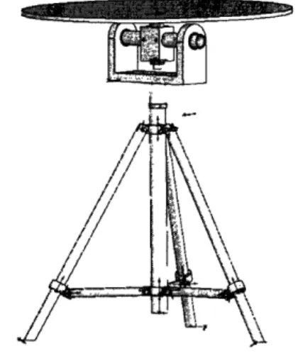
Because there could be no hardware above or below the 1.5 meter in diameter table, it became clear that the table had to be held from its sides. It was decided that the table would be held in a frame. The frame, shown in Figure 4 on the next page, would rotate independently of the table along the tilt axis. The table itself then would be rotated within the frame, constituting the second mode of rotation. The frame was first suggested
to be circular to fit the circular table, but the design was changed to an octagonal
structure. As an octagon, eight straight segments could be welded together to form a
circle. The segments were made out of square box extrusion so that gears and bearings
could be attached easily to their flat faces. This also allowed for an easy manufacturing process for each one of the eight pieces was identical, bar specific holes drilled into them.
because a hexagonal figure would interfere with rotation about the tilt axis under the symmetrical and manufacturing constraints.
Figure 4:Octagon Frame with Hexagon Backbone Inside
Next, the size and thickness of the box extrusion needed to be selected. After reviewing common sizes in the scope of the project, the choices were narrowed down to a
2" x 2" or a 3" x 3" cross section with a 0.125" or 0.25" thick wall. Keeping in mind the
design of the ball bearings that would eventually hold the table within the frame, the 2" x
2" cross section box extrusion was selected. Using CosmosWorks to model the loads and
deflections of the table upon the frame, it was decided that it was not worth the cost or the
extra weight to purchase the 0.25" wall, so the 0.125" wall was chosen. Figures 5 and 6
below show a deflection of eight thousands for the 1/8" wall and six thousands for the 1/4"
wall.
Figures 5 and 6: Estimated Deflection of the Frame using CosmosWorks FEA Program
Srm .soormr .Iaom .slaoaa .soarmr smplna nlrmr .roluar .xrsr-m, .IRum ,olrom wlDom ala.oer lyllbOa
. 9
vA. Ball Bearing Rollers
At this point in design, the table was modeled as a half inch thick, five foot in diameter aluminum gear. The next design challenge was to find a way to suspend the
table in the frame as the frame rotated around that tilt axis that also allowed the table to be rotated around its own horizontal axis. To keep the table in plane, three pairs of ball bearings were fastened around the circumference of the octagonal box extrusion. Each pair was mounted so that a half inch gap was left between the surfaces of the two ball bearings. Although only one roller in each pair would feel forces at any given time, both were needed to support the table when it was turned upside-down.
The original design called for a removable table that would transfer the
Heliodome between its two modes. This meant that one set of rollers would have to be easily removable and later locked back in place. The best solution to this problem came
in the form of toggle clamps. Toggle clamps are levers that are able to be locked in one
of two positions. The ball bearing would then be attached to the end of a cantilever, held to the frame by a toggle clamp. Although this may have been the best solution, it still added complexity and moving parts to the project. Instead, it was decided that the half ellipse itself could be put on or removed to switch between the two modes. This way only one table was needed and it could be permanently secured within the frame. This change in the design eliminated the cost of an extra table, the storage space required to hold it, and the cumbersome nature of installing a fifty pound, five foot in diameter object every time the modes need to be changed.
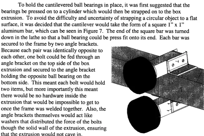
To hold the cantilevered ball bearings in place, it was first suggested that the
bearings be pressed on to a cylinder which would then be strapped on to the box
extrusion. To avoid the difficulty and uncertainty of strapping a circular object to a flat
surface, it was decided that the cantilever would take the form of a square 1" x 1" aluminum bar, which can be seen in Figure 7. The end of the square bar was turned down in the lathe so that a ball bearing could be press fit onto its end. Each bar was
secured to the frame by two angle brackets. Because each pair was identically opposite to each other, one bolt could be fed through an
angle bracket on the top side of the box
extrusion and secured to the angle bracket
holding the opposite ball bearing on the
bottom side. This meant each bolt would hold
two items, but more importantly this meant there would be no hardware inside the extrusion that would be impossible to get to once the frame was welded together. Also, the
angle brackets themselves would act like
washers that distributed the force of the bolts
though the solid wall of the extrusion, ensuring
that -LII"L the nvtnri;r'i 311 n uln,.,VV 1 l A nr t ,roii ;iIFigureL ,7: Solid Model of Ball Bearing Rollers11
B. Spur Gears
Spur gears were mounted to the octagon frame for two purposes: First, the gears
hold the table stationary within the plane restricted by the ball bearings. Secondly, a powered gear provides a mode of rotation around the horizontal axis.
The first concern in deciding where to position the gears was to define where the
powered spur gear would be located. This gear would be powered by a motor that
weighed no more than three pounds. Thus, the biggest concern was to place the mass of the motor as close to and symmetric with the tilt axis. The first design incorporated four
additional gears placed evenly around the octagon frame. With this configuration, the weight of the table when standing vertically would rest evenly on two spur gears and
alleviate all stress from the powered gear. Yet, at any one point, it was most likely that either only three of the five gears would be guiding the table or the table would be over constrained. Thus, the final design boiled down to three gears, all symmetric about the tilt axis.
The next design parameter to be decided upon was how to mount the gears to the
octagon frame. The original concern was to make the outer diameter of the table as close
to the inner diameter of the frame as possible. The gears were to be pressed onto a shaft
and mounted inside of the box extrusion, using holes drilled in the top and bottom
surfaces as bearings for the shaft. It was later decided that this design would incorporate too many complications in the construction and maintenance of the gears. Instead, the gears were mounted inside of the octagonal frame, using two plates attached to the top and bottom surfaces of the frame to hold the axis of the gear shaft 1" from the face of the inside surface. Again, the plates were mounted opposite from each other, so that a bolt
could be fed though both of them, eliminating the need for hardware inside the frame.
The 1/2" face width of the gear matched the /2" thickness of the table. The gear selected was 16 pitch which is most commonly used with a /2" face width. The pitch diameter was selected to be 1.5" so that the major radius would be just less than 1". These features can be seen in Figure 8.
To keep the shaft from moving along the axial direction, both ends of the shaft were first threaded. Then, two nuts were locked against each other on the threaded shafts. Nylon radial and thrust bearings were first used to reduce friction between the locking nuts and the two aluminum plates as well as the rotation from the shaft, but then changed to ball bearings to further reduce friction.
VI. The Table
The table was by far the most intricate and challenging aspect of the project to design. It took two weeks simply design the first concept. The main concern of this parameter was to find a material that was thin, incredibly stiff, and able to have gear teeth mounted to the outsides. The table was originally modeled as a five foot in diameter, /2" thick aluminum gear. After some research it was found that a solid piece of aluminum this large would alone cost $1,100. After adding the cost of finding and using a waterjet
big enough to cut the gear as well as shipping such a large item, this option was quickly
turned down. Further exploring the idea to make the table out of one solid piece, webbed cardboard, reaction injection molding, and structural foam were looked into as possible materials but came with no concrete solutions.
In addition, the design of the table had to incorporate a way to hold or mount various sized scale models, the ellipsoid shell, two different sized cameras, and a wide variety of samples all within a 0.002" tolerance that was able to be repeatedly accurate. The axis of rotation had to intersect exactly at the focal point of the ellipsoid shell, which meant the azimuth axis would run through the plane of the face of the table and the horizontal axis would lie through the center of the circular table, orthogonal to its face. The design also specified that there were to be no obstructions within a five degree pitch from the edge of the sample above or below the table.
A. The Unistrut Backbone
To jumpstart the design process, the bare essentials of the table were examined.
The table would need to be circular, have gears around the outside, and a hole in the
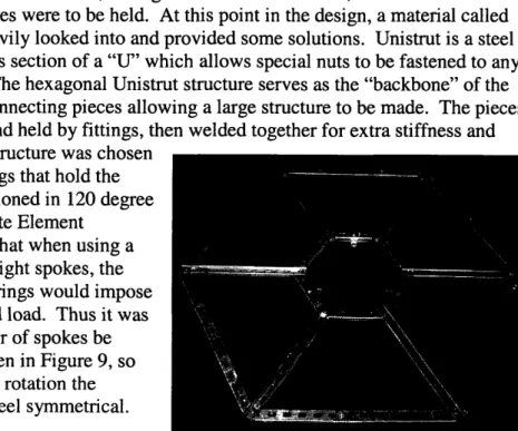
center where the samples were to be held. At this point in the design, a material called Unistrut was being heavily looked into and provided some solutions. Unistrut is a steel
extrusion with the cross section of a "U" which allows special nuts to be fastened to any
point along its track. The hexagonal Unistrut structure serves as the "backbone" of the table, with its easily connecting pieces allowing a large structure to be made. The pieces were first positioned and held by fittings, then welded together for extra stiffness and
n+kl:I:+~, A k L...- . . A. ..,..L ....
SLaUI1ILy. /-i 1ltagoll SLtL-UcLUl Was cLIoUSIn1
because the ball bearings that hold the
table in plane are positioned in 120 degree
intervals. Though Finite Element Analysis it was found that when using a structure with four or eight spokes, the evenly spaced ball bearings would impose an unevenly distributed load. Thus it was decided that the number of spokes be
divisible by three as seen in Figure 9, so
that no matter where in rotation the
Unistrut frame would feel symmetrical.
There are a few key features on this structure. Firstly, the spokes that connect the inside ring to the outside ring have their opening upwards. This allows for six channels that use an adjustable sliding clamp to hold different sized models or the ellipsoid shell. The other spans of Unistrut that make the inner and outer rings are facing down,
providing a large surface area for the second part of the table to be bonded to. All of the
fittings are attached from the underside of the structure so that the entire upper face is at one uniform, flat height. There is one fitting connecting the entire center ring together with three tabs protruding from its sides. These tabs are threaded to house springs used in
holding the samples. Thus, the Unistrut frame provides a stiff backbone with the
capability to secure different sized models to it. B. Honeycomb Aluminum Base
Because of the Unistrut frame, the table no longer needed to be made from one solid piece. After reviewing the materials previously studied, it was decided that honeycomb aluminum would be the best material for the base of the table. Honeycomb aluminum is lightweight, extremely stiff, wajerjet friendly, and able to be purchased in
large, /2" sheets. We decided to make six pieces to cover the six segments of the Unistrut frame. One of the six segments is pictured in Figure 10 below. A 4' x 8' sheet of
honeycomb aluminum was purchased and cut into six equal parts before it was shipped. By cutting the sheet into parts, the shipping cost was cut down from $300 to $30. Also,
the parts were then small enough to be waterjetted on campus, instead of having to be professionally outsourced.
C. Nylon Gears
Next, the gears had to be fastened to the outside of the honeycomb aluminum. It was preferred to keep the entire table at /2" thickness for that is the maximum clearance through the ball bearing rollers. To secure the gears to the aluminum, a type of dovetail technique commonly used in woodworking to join to pieces of wood was employed. The first design called for the nylon to have a dovetail pattern on the opposite side of the gears that would have a female fitting cut into the honeycomb aluminum. This allows the gears
to fiercely oppose any radial or sheer forces that would try to separate them from the honeycomb aluminum. Later the dovetail was changed to a circular design with a slit at the top. The circular design was used to make waterjetting the piece quicker and easier and because the honeycomb aluminum is prone to denting, especially at sharp edges. This unique design can be seen in Figure 11. With the slit in the design, the circular male inserts were able to be pinched so that installation into the female fitting was easier. After installation, dowels were press fit into the inner circle of the male fitting, pressing
the rest of the fitting against the honeycomb aluminum. The friction resulting from this
force is enough to prevent displacement in the axial direction due to the weight of the gear itself. Because the ball bearing rollers take all the force from the table in the axial direction, the nylon gears only feel a force in the radial direction.
The gears and the honeycomb aluminum segments fit together similarly to a
jigsaw puzzle. The male parts on the gear and female parts on the aluminum cut on the waterjet were made to have no gap in between each other. The assembly of these parts is shown in Figure 12 on the previous page. By the nature of the waterjet, the entrance cut on the top of the piece is more exact and slightly wider than the exit cut on the bottom
half because the water fans out as it cuts through the material. This effect was countered
by matching the wider face on the gears with the narrow face on the honeycomb aluminum. Another advantage to the jigsaw structure is that the gears cover the dent prone core of the aluminum. Also, because the gears span from one honeycomb aluminum segment to the next, they help hold the segments together.
Nylon was chosen to make the gears from after analyzing the shear stresses on the gear teeth by using the Lewis formula7, which states:
G = (Forcetang * Numb teeth) / (Pitch diameter * Face width * Lewis form factor)
At maximum current, the motor can output 7.1 Newton-meters of torque, resulting
in a 370 Newton tangential force. Thus, for this nylon gear with a face width of 0.5 inches, the maximum shear stress is 38 MPa. As a conservative estimate, nylon has a tensile strength of 62 MPa, leaving a safety factor of 1.6. Also, the motor will seldom, if at all, be run at maximum power.
D. Steel Track
A 1/32" thick circular steel track which serves several purposes was installed on both sides of the table. The track makes a smooth, level surface that the ball bearings can roll on with graduated breaks between the pieces of track. Because it is made out of steel as opposed to aluminum, it has an infinite wear life at low loads. The track also makes sure that the nylon gears can not move axially out of their positions. Also, the track helps prevent the aluminum honeycomb pieces from bending at their joints. Although the aluminum honeycomb is extremely stiff within one piece, the table relies on the Unistrut
backbone and the steel track to secure the joints between the honeycomb pieces. The track would have been better suited with stainless steel to prevent rust. This detail was
overlooked until the track was installed. To protect it from rust, the track was painted and is only used in a low humidity environment. If these precautions are not enough, the track will be disassembled and remade with stainless steel.
E. Sample holder
The next design challenge was to find a way to hold various sized samples within the center of the table while minimizing the shadows created by obstructions. The tilt axis of rotation had to lie on the face of the sample at all times. Placed above and below the sample are two different circular apertures. The apertures must be able to be removed and replaced within a 0.002" tolerance. The sample and both apertures had to be
accessible and locked in place from the underside of the table.
The final design that was chosen works by using the force from the locking springs to sandwich the sample between the apertures. The apertures used are made from 0.0315" thick steel and are as thin as possible to reduce the shadow cast on the sample by the aperture at large incident angles. Each spring can supply five pounds of force at maximum compression. Thus, to prevent deflection of the apertures, the sandwich structure is reinforced by structural apertures which are made of 0.0625" steel. The first structural aperture is bolted to the top of the sandwich and is suitable for any combination of apertures and samples. Next, the apparatus is turned upside down and the top aperture is put in place. The sample is then situated on top of the first aperture and covered by the second aperture. The second structural aperture is twisted into place. Finally, the springs are released, sandwiching the entire apparatus into place. This equipment is depicted in Figure 13. The springs are screwed into the Unistrut fitting, so the force on the apertures and the position of the springs can be adjusted by screwing or unscrewing them.
The repeatable accuracy of the apertures is derived from the accuracy of the waterjet. The apertures themselves share the same dimensions as the inner hexagon formed by joining the six honeycomb aluminum pieces together, which were cut by the
waterjet. Thus, each wall provides a point of registration to align the aperture in the
center. Plainly put, the hexagon aperture must fit in the hexagonal hole. The sample holder is the only mechanical element that has not yet been mechanically tested.
Honeycomlb Anlillnu 3/8" Bolt Stllctural Aperture Apetture Axis of Rotation
l /
l
?
Unistrut TIlistrut Nut Locking Sprilgs Sample 13°Ilcident Light
Figure 13: Construction of Sandwich Locking Mechanism
UTnistut Fitting
VII. The Frame
The frame of the Heliodome platform is primarily made of Unistrut. The only exceptions are the 4" x 4" square box extrusions that house the pillow block bearings that take the load from the table. Using the Unistrut allows for an adjustable and detachable base which cuts also cuts down on welding costs and allows for the octagon frame to be removed in case of repair or maintenance. For many weeks, the frame contained two triangular extensions to the rectangular base to help support the 4" x 4" posts. These bulky extensions were replaced with four cross members as seen in Figures 14 and 15 below. This advancement made the machine less bulky and freed room for the
counterweight to rotate through. The frame in Figure 15 accurately represents the finished frame, except for four cross members that were too challenging to solid model. The frame is held up by eight feet. Each foot is screwed onto a bolt which serves two purposes by also holding together a Unistrut fitting. The height of each foot is able to be adjusted by screwing or unscrewing it from the bolt. Also, the base of the foot is on a
swivel mount so that the leg can turn to accommodate any unleveled surface it is placed
upon.
Figures 14 and 15: Evolution of the Frame
A. Pillow Block Bearings
Mounted inside each 4" x 4" post is a pillow block bearing. These bearings are used to account for misalignment along the tilt axis. The housings for the bearings were slimmed down to fit snugly within the post to minimize the length of the two cylinders
that are welded to the octagon frame. The grease fitting was positioned for easy access
for maintenance purposes. The bearings are held to the 4" x 4" post by four bolts with socket heads. The socket heads are used because in case the bearing had to replaced or
removed, it is easier to fit an Allen wrench into the post than a regular wrench to unscrew
the nut and bolt assembly. Figure 16 on the next page shows one of the bearings situated
in the post.
B. Slip Ring
The slip ring, seen on the next page in Figure 17, is a device that is able to
transmit electrical power and signals through a rotary joint. The ring uses two leads per wire that are held to a copper ring by a spring to sustain electrical contact though rotation. The slip ring powers a motor mounted to the rotating octagonal frame. If the motor was
connected by conventional wires, the wires would get wound around the azimuth axis as
the frame rotated. With the use of the slip ring, the octagon frame is able to be rotated
though all 360 degrees as many times as needed without electrical wiring problems. The ring itself had to be disassembled and its base modified to be able to be mounted to the 4"
x 4" post.
Figures 16 and 17: Close up shots of the Pillow B C. Counterweights
In order to keep the center of mass as close to the axis of rotation of possible, a system of counterweights has been integrated into the design of the Heliodome platform. The two lead counterweights are screwed onto a 3/4" aluminum rod that is cantilevered off of the cylinders held by the pillow block bearings. Each rod has a threaded hole in two inch increments. Thus, with two five pound counterweights on each rod and each rod measuring twenty inches in length, a maximum amount of 400 inch pounds of torque can be supplied by the counterweight system. For very light samples, the aluminum rods themselves can be easily removed. This system is important for it helps the motors not only move the combined weight of the table, ellipsoid shell, and scale models, but also helps the motor maintain the apparatus at a certain angle without expending energy. Care must be exercised when removing heavy counterweighted objects from the table for the
counterweights will swing the Heliodome table back to its equilibrium position on the
azimuth axis.
VIII. Power and Movement
The next big part of the project was getting the table to move around its two axis
with computer controlled precision. This section goes over all the electrical and
mechanical components that make the table move.
Two motors are used to power the Heliodome table about the azimuth and horizontal axis. The motors were selected based on their torque and RPM outputs. The
motor that powers the horizontal axis rotation is a very conventional DC motor with an
integrated encoder. Because the motor is connected to a 1.5" diameter spur gear that
turns a 60" diameter gear, it was important to find a motor with high RPM and relatively
low torque. The motor shaft is connected to the gear shaft via a spider coupling. This device was selected because it has a star shaped rubber piece that allows for
misalignment between the shafts. The first motor that was purchased for this application
was underpowered. Although the table rotates upon all ball bearings, the bearings themselves are a far distance from the axis of rotation, thus enacting a lever arm which
creates large amounts counter torque resulting from small amounts of friction at the bearings. A picture of this motor can be found below in Figure 18.
Figures 18 and 19: Pictures of the rotary and tilt axis motors, respectively.
The motor for the tilt axis was much more complicated to find and install. The gear train from the rotation of the motor to the rotation of the table about the azimuth axis
provided a 2:1 reduction. Thus, unlike the previous motor, this motor needed to have
high torque and low RPM. An unconventional, small, brushless motor with a 125 inch-pounds of torque at 30 RPM was used because its unique shape, seen above in Figure 19. Theoretically, the entire system can be balanced by counterweights which would then require only a small amount of torque to make it rotate. Yet, with such counterweights, the table would have a very high moment of inertia, requiring a good amount of torque to accelerate it.
The second motor specified that it could only take a 17 pound load in the radial direction due to weak zinc bearings. The maximum torque output of the motor is 125 in -lbs. The pitch angle of the gear was 14.5°, which means that 25.8% of the load is applied
in the radial direction. Using a gear that is 3.75 inches in diameter, the motor creates a maximum force of 66.6 pounds, applying 17.2 pounds in the radial direction. Thus a 3.75" in diameter gear was used to ensure even at maximal output by the motor, the
equipment was used within the boundaries of the safety limit.
After purchasing and installing the motor that controls the tilt axis, it was found that its encoder had only six counts per revolution. This translates to only 11 counts per
revolution on the tilt axis, or a 32 degree accuracy when the specifications called for 0.5 degree accuracy. Thus, a new encoder had to be purchased and installed. It was a
challenge to install the encoder for it was not originally incorporated in the design. It was decided that an encoder with a bore-thru design would be the most applicable. At first, the only circular rotating component available to mount the encoder to were the 1.5" in diameter cylinders that are mounted to the octagonal frame. Yet, encoders with a bore larger than 1" are rare and expensive. Instead, the encoder was mounted to the gear that is on the tilt axis motor shaft. The hub of the gear had to be machined down from 2" to l". The new encoder has 1000 counts per revolution, which translates to 1866 counts per revolution on the tilt axis after passing through the gear reduction. The 0.5 degree
accuracy specification was not only met, but surpassed with the tilt axis now having an
accuracy of 0.20 degrees. C. Power Supply
The power supplies, being electrical in nature, were not originally part of this
project. Yet, some of the properties of the power supplies influence and directly effect
the mechanical components of the Heliodome platform. After we had found that the
rotation axis motor was underpowered, a search for a new motor began. The new motor that was purchased was available with either 12 or 24 Volts DC. The maximum safe operating current though the motor was limited to 30 Amps for the 12 Volt motor and 15 Amps for the 24 Volt motor. Because the slip ring could only handle 15 Amps on each
channel, the 24 Volt motor was preferred. There were far more power supplies available
with a 12 Volt output, so it was decided to use the 12 Volt motor and make a parallel circuit through the slip ring if all 30 Amps were needed. Fortunately, the table only requires four amps at maximum to rotate, so the parallel circuit is not required.
IX. Discussion
Although research has been done on both heliodons and goniophonometers, the
Heliodome platform sets itself apart as a unique research by incorporating functionality
from both devices as well as tackling other design challenges. There are and have been a variety of simple two axis tables on the market available for consumer use but these
tables usually measure one foot in diameter at most. Scaling up this type of instrument
five fold came with a wide variety of complications. Also, mechanisms such as the spring loaded sample holder as well as the design and assembly of the five foot circular table have never been done before. Thus, it is important to discuss only the parts of the
Heliodome platform that are unique.
The biggest design challenge in this project was the design and assembly of the five foot table. It had many requirements and parts that all had to coincide. From the beginning of the project, it was unclear if the puzzle-like assembly of the table using water jet precision to make the individual parts would actually work. Each part was
made with zero tolerance and theoretically was made to fit together with no gaps. This
design concept was also used when making the inner ring of the Unistrut backbone, but
due to manufacturing inaccuracies, the ring's radius ended up on average 1/16" larger than it was intended. Inherit manufacturing properties such as draft angle on the water jet and a 0.001" tolerance in positioning also raised questions as to whether the parts would fit together. Yet, in the end, the elasticity of the honeycomb aluminum and the nylon gears as well as the slit in the circular dovetail inserts allowed for enough play to make up
for any inaccuracies.
In retrospect, using a solid sheet of aluminum instead of honeycomb aluminum
may have been a better design. Originally, this idea was thrown out when a 5' by 5' sheet of 1/2" thick aluminum was quoted to cost $1,100. Yet, by the end of the project two 4' x 8' sheets of honeycomb aluminum as well as one 2' by 3' sheet of nylon had cost $750. Instead of a /2" thick 5' x 5' sheet, a 1/4" thick 4' x 8' piece could have been purchased and cut into six pieces in the same manner the honeycomb aluminum was
constructed. Large segments of material not crucial to structural stability could have
been cut out to cut down on weight. Gears could have been waterjetted into the
aluminum segments, eliminating the interface between the gear segments and the circular table and greatly simplifying the design. The cost from waterjetting would have been about the same, if not less, than the current design. But most importantly, the table itself
would be much more durable and less susceptible to damage. The honeycomb within the
honeycomb aluminum, although sealed from all sides, is very easily damaged from a lateral direction. For example, when waterjetting small holes for positioning into the honeycomb aluminum, the honeycomb itself was blown out of its positioning, disturbing
the structural components within a two inch radius of each hole. To make up for this possible lack of strength, Bondo was injected into each hole and later sanded down to size. If at some point the table needs to be rebuilt, this option would have to be further
investigated.
The circular steel track that runs along both sides of the table was not originally part of the design, but had many unforeseen advantages as previously touched upon. It
would have been better for corrosion resistance if these pieces were made from stainless
steel. Although stainless steel is harder to machine, these pieces were cut on the waterjet, so this added difficulty would not have been a problem. The current steel track has some corrosion resistance from a layer or paint, but the paint is likely to flake off with constant wear by the ball bearing rollers. Although the Heliodome is to remain in a low humidity, constant temperature environment, these pieces may still rust. If these pieces need to be replaced, it is a must that they be replaced with stainless steel.
Another design feature required of the positioning system that came later during
the project required that the sample was able to be loaded and unloaded only from the bottom side. To access the top side, the elliptical shell would have to be removed, creating a big inconvenience to the user. Thus, a rotating lower diaphragm was designed to fit past the three supporting springs, then rotate to lock the assembly together.
Lastly, the grazing angle constraint on the table originally posed a quite a
challenge. As previously stated, there could be no hardware above or below the sample, any hardware to its sides had to be minimized. The limit on the smallest possible grazing
angle was dependant upon the thickness of the diaphragm that holds the samples. Even though the diaphragm is only one millimeter thick, at low grazing angles of around 5
degrees, the diaphragm can cast a 10 mm shadow which covers a significant amount of the sample with the 5 cm aperture selected. Thus, it was not necessary to remove objects
within five degrees above or below the plane of the sample because the light would have been blocked by the aperture anyway. Both sides had to be clear of obstructions to allow reflection and refraction studies.
X. Conclusion
Overall, the Heliodome platform is a versatile, durable machine. It concurrently
functions as both a heliodon table to study shadows and a goniophotometer platform to measure light flux. Both modes incorporate an adjustable clamping design, allowing a wide range of models and samples to be held in position for study. Also, an adjustable counterweight system allows for all these samples to be neutrally balanced around the axis of rotation, reducing the power requirement for the motors, while at the same time
eliminating the need for a braking system. The Heliodome table was built to last, made
with supporting cross members and bound with strong epoxy.
It meets all of the requirements that were originally set, and in cases such as
rotary position accuracy it exceeds the specifications. Both axes rotate smoothly and without approaching the maximum current available to the motors. Many of the
manufacturing processes in which it was unsure whether the components would meet the tolerances or even fit together in the first place, such as making the octagon frame or
assembling the puzzle like table, came out surprisingly well. All of the components are
easily accessible for repair or replacement.
Although there are some minor mechanical elements that are yet to be made, the Heliodome platform is in full working condition. The next step is to hook up the electronics. The program that will be used to interface with the user has been made, but not tested. A feedback control circuit needs to be set up to be able to move and then keep the table at a specified angle on both axes. The computer program also must be able to
couple the tilt and rotation axis by using measurements from the rotation position sensors. Wiring from the power supplies, through the slip ring, and to the motors must also be put
together and tested. In all, the electronics are quite a formidable task on their own. Yet, with some luck, the Heliodome should be ready for use in the near future.
XI. Bibliography
[1] Scartezzini, J.L., Advances in Daylighting and Artificial Lighting, Proceedings of Research in Building Physics, 2003.
[2] Bodart, M., DeHerde, A., Global energy savings in office buildings by the use of
daylighting, Energy and Buildings 34:421-429, 2002.
[3] Libby B., The evangelists of natural light - Selling architects on the benefits of the
sun's illumination, Herald Tribune, June 19, 2003.
[4] Hubbard, (G., Clanton, N., Franta, G., Less is more: lessons learned from the Low
Energy Super Store, Proceedings ISES Conference, 2003.
[5] M. Andersen, C. Roecker, J.-L. Scartezzini, Design of a time-efficient
video-goniophotometer combining bidirectional functions assessment in transmission and
reflection, Solar Energy Materials and Solar Cells, vol. 88 (1), pp. 97-118, June 2005.
[6] Ward, G., Measuring and modeling anisotropic reflection, ACM SIGGRAPH
Computer Graphics, vol. 26 (2), pp. 265-272, 1992.