Publisher’s version / Version de l'éditeur:
Experimental Mechanics, 18, 1, pp. 25-34, 1978-01
READ THESE TERMS AND CONDITIONS CAREFULLY BEFORE USING THIS WEBSITE. https://nrc-publications.canada.ca/eng/copyright
Vous avez des questions? Nous pouvons vous aider. Pour communiquer directement avec un auteur, consultez la première page de la revue dans laquelle son article a été publié afin de trouver ses coordonnées. Si vous n’arrivez pas à les repérer, communiquez avec nous à PublicationsArchive-ArchivesPublications@nrc-cnrc.gc.ca.
Questions? Contact the NRC Publications Archive team at
PublicationsArchive-ArchivesPublications@nrc-cnrc.gc.ca. If you wish to email the authors directly, please see the first page of the publication for their contact information.
NRC Publications Archive
Archives des publications du CNRC
This publication could be one of several versions: author’s original, accepted manuscript or the publisher’s version. / La version de cette publication peut être l’une des suivantes : la version prépublication de l’auteur, la version acceptée du manuscrit ou la version de l’éditeur.
Access and use of this website and the material on it are subject to the Terms and Conditions set forth at
Stress state in tempered glass plate and determination of heat transfer
rate
Sinha, N. K.
https://publications-cnrc.canada.ca/fra/droits
L’accès à ce site Web et l’utilisation de son contenu sont assujettis aux conditions présentées dans le site LISEZ CES CONDITIONS ATTENTIVEMENT AVANT D’UTILISER CE SITE WEB.
NRC Publications Record / Notice d'Archives des publications de CNRC:
https://nrc-publications.canada.ca/eng/view/object/?id=55845d2c-cf30-4999-92a6-65041ce7a216 https://publications-cnrc.canada.ca/fra/voir/objet/?id=55845d2c-cf30-4999-92a6-65041ce7a216Ser
TH1
N21d
no.
745
National Research Council of Canadac . 2
Conseil national de recherches du Canada BLDG
STRESS STATE IN TEMPERED GLASS
PLATE A,ND DETERMINATION OF
HEAT-TRANSFER RATE
by
N.K. Sinha
4
~ e ~ r i n t e d from
Experimental Mechanics Vol. 18, No. 1, January 1978 1 op.
-*
%'
R e e d & - . E ~ - ~RESFA2Cj.j
~-
FESRARY
-
6
MAf? 11
1978
NATIONAL R E I A R M COUNCILu
DBR Paper No. 745Division of Building Research
Le trempage est largement utilisb pour la fabrication de verre de s ~ c u r i t 6 pour des raisons d'bconomie autant que pour des raisons de s6curit6. Les etudes en laboratoire du procede de trempage et de I'effet de renforcement qu'il produit sont g6neralement limitees
3
des 6chantillons rectangulaires. Les rksultats sont donc valables pour cette configuration geometrique particuli8re. Le present rapport dgcrit un modele de contrainte simple dans un 6chantillon de verre plat trempe. Le modele, qui utilise des 6quationsphoto-elastiques pour determiner les composantes
tri-dimensionnelles de contrainte, a servi
3
Btablir la birgfringence accidentelle dans un 6chantillon de verre rectangulaire soumisA
un transfert de chaleur uniforme et symetrique, une temperature o'u le verre se conduit comme un materiau 6lastique parfait, sans relschement de tension pendant la phiode experimentale. Une mbthode pour determiner le coefficient de vitesse de transfert de la chaleur a pu gtre mise au pointh
partir de I'analyse de la birefringence accidentelle. Cette technique utilise I'6chantillon de verre comme un transducteur optique sans jamais modifier le passage nature1 de la chaleur par convection forcee ou refroidissement de contact.Stress State in Tempered Glass Plate and
Determination of Heat-transfer Rate
Three-dimensional stress state in thermally tempered glass plate, determination of the stress components and a photoelastic method of evaluating heat-transfer rate during tempering are described
by N.K. Sinha
ABSTRACT-Thermal tempering is widely used to manufacture safety glass for economic as well as for certain safety measures. Laboratory investigations of the tempering process and the resultant strengthening effect are generally limited to rectangular specimens. Results are, therefore, appropriate for this particular geometry. This paper describes a simple stress-state model of a tempered flat glass specimen. The model, developed using photoelastic equations to determine the three-dimensional stress components, was used to predict the transient birefringence in a rectangular glass specimen subjected to uniform and symmetrical heat-transfer conditions, at a tempera- ture where glass behaves as a perfect elastic material with no stress relaxation within the experimental time. A method of determining the coefficient of heat-transfer rate was then developed based on the analysis of the transient birefringence. This technique uses the glass specimen as an optical trans- ducer, and does not affect, in any way, the natural flow of heat by forced convection or contact cooling.
Nomenclature
C. = stress-optical coefficient
c = subscript for central mid-plane value,
specific heat
A d = scattered-light fringe separation E = Young's modulus
h, , h, , h, = coefficient of heat-transfer rate in directions
x, ,x2 and x3, respectively
K = constant
k = true thermal conductivity
29, = length
2f2 = width
2 t = thickness
s = subscript for surface value, half thickness
R ,
,
R 2 , R, = relative retardations in polarized light propagating along x, ,x2 and x, respectivelyx, ,x2 ,x3 = Cartesian coordinates
N.K. Sinha is Research Officer, Geotechnical Section, Division of Building Research, National Research Council of Canada, Ottawa. Ontario, Camda KIA OR6.
Paper was presented at 1977 SESA Spring Meeting held in Dollar, TX on May 15-20.
Original manuscript submitted : November 14, 1976. Final version received : July 18, 1977.
(Y = coefficient of linear thermal expansion
k
/3 = - = thermal diffusivity
e
c13 = excess temperature over the ambient at any time
8, = initial excess temperature
Q = density
u1
,
u2, u3 = principal stressesa!, a: = components of principal stress a; along i due to the heat flow along j and k , respectively,
i # j # k X = wavelength of light
v = Poisson's ratio 7 = time in seconds
Introduction
The present lack .of basic knowledge of the dynamic rheological response of unstabilized soda-lime-silica glass* makes it impossible to give more than a good qualitative description of the industrial tempering process. Opti- mization of this process, however, is economically essential for the glass industry. The shape of the object (usually in the form of a shaped flat plate) to be tempered in practice and its chemical composition are predetermined. Hence, optimization can be obtained only by a proper choice of the initial temperature and cooling rate. Experi- ments have been conducted to see how these conditions influence the transient and final residual stresses and the breaking strength of common plate glass.
Experiments were carried out on rectangular specimens of different dimensional ratios. The breaking strengths of various groups were determined in a four-point loading system. It was observed that fractures usually originated in a preferred zone near the middle of the specimens.
The mid-plane tension or the degree of temper can be determined accurately by measuring the corresponding birefringence with graduated quartz wedges or, preferably, with a Babinet compensator.' This method, however, is limited to tempered specimens up to about 5 cm wide. The scattered-light oblique-incidence technique with a
Commonly known ar plate glass' or 'sheet glass'.
Reprinted F r o n ~ : EXPERIIUE
Z
T A L
W E C H A V I C S , Vol. 18. Vo. I , 15-34. Jurlur~r) 19iBlaser was developed2 to measure the stresses in a large sheet of tempered glass. This method, in its normal incidence mode, has been applied to measure the degree of temper in small rectangular specimens. It was noted that there were discrepancies, far beyond the error of measurements, between the values of the central mid-plane tension determined by the scattered-light technique and those measured by the compensator method. The differences in the two values were found to be influenced by the geometry of the specimens.
In an attempt to use the ion-exchange method of flaw detection to obtain a measure of the influence of tempering conditions on the density of flaws on the surface of tempered glass, it was observed that the resulting crack directions also were influenced by the geometry of the s~ecimen.
A simple model of stresses has been found to be suitable for the complete analysis of three-dimensional stress components in a tempered glass specimen. This model was developed primarily for setting up photoelastic equations. The complete stress state can be determined then by conventional photoelastic methods. Knowledge of stress distributions can be used to explain the influence of geometry on the breaking strength, the discrepancy between the scattered-light and the transmitted-light values of stresses, and the mode of ion-exchanged crack propagation.
A technique was developed that used this model and birefringence measurements to compute the cooling rate of specimens subjected to the usual methods of cooling glass. In this way, particular industrial cooling conditions could be related to the corresponding heat-transfer rates without any of the uncertainties and difficulties associated with the methods it replaced.
Thermal Tempering
The process of thermal tempering involves heating the glass to a temperature higher than 600°C and then sub- jecting it to rapid cooling, either by forced convection or by mechanical contact. This results in an approximately parabolic stress distribution in the glass plate with com- pression at the surface and tension in the mid-plane. The compressive stress at the surface is nearly twice the tensile stress in the middle plane. The mid-plane tension seems to give a measure of the stress distribution and is commonly referred to in the literature as 'degree of temper', often represented by the corresponding birefringence per unit length. The stress condition is interpreted on the basis of the phenomenological photoelastic relation between stress and birefringence.
Thermally tempered glass, popularly known as 'safety glass', is stronger than ordinary glass. This is due mainly to the compressive layer at the surface. The surface compression also enhances the resistance to abrasion. The mid-plane tension increases the safety factor in the sense that if the glass breaks, it does so into small frag- ments that are less harmful than the sharp-edged pieces into which ordinary glass generally breaks.
Theories of tempering have been developed, over the
last twenty-five years, by Bartenev in 1948,' Aggarwala
and Saibal in 1961' and Lee et a l . in 1965.5 Each theory is a refinement of its previous one, and each has its own merits. The theoretical basis of Lee et a l . is closer to physical reality. They developed their complicated mathematical theory on the basic assumption that glass behaves as a thermorheologically simple material with a constant activation energy over the entire tempering range
of temperature. Sinha6 showed that mechanical response of soda-lime-silica glass (which is used almost exclusively to manufacture safety glass) at elevated temperatures can be considered as rheologically simple only in its equilibrium structural state, but this does not apply to the unstabilized glass. The structure of glass is influenced by its previous thermal history. Sinha6 suggested that the theory of tempering should take into account structural changes during the tempering process. The variation of physical properties such as the linear thermal-expansion coefficient, volumetric expansion, Young's modulus and Poisson's ratio with temperature, are strongly dependent on the thermal history. It is impossible to develop a comprehensive tempering theory without giving due- consideration to the structure.
Proposed Model for Stresses
Thermally load a rectangular glass plate. Thermal loading can be applied in different ways but only those where the plate is heated or cooled uniformly and symmetrically over the surfaces by conduction or forced convection will be considered here. The forced-convection cooling is similar to that used generally for the industrial glass-tempering process. Conduction cooling is also applied in the form of 'contact cooling' process, but this has not yet been developed on a commercial basis. Let the stresses
developed in the medium be represented by :
In the present case, the Cartesian coordinates coincide with the direction of the principal stresses. For the
boundary conditions assumed, the shear stresses are :
i r j
and the principal stresses are :
a. = a, i = j = 1,2.3. no sum
The fundamental basis of the present model of three- dimensional stresses in a rectangular plate depends upon two important assumptions :
( 1 ) Consider Fig. 1 which shows a rectangular specimen, the length, width and thickness of which are respectively
2 4 , 2 4 and 2P3. Heat transfer h, along the axis parallel
to ,ul produces a pair of equal stresses a: and a:, the subscripts of which denote the principal directions; the superscripts, the corresponding heat-flow direction. The stresses are developed in the directions, x, and x 3 , normal to that of heat flow, as heat transfer in the direction
xl produces a temperature gradient in x, direction only.
Similarly, heat transfer h2 along x2 produces
d
,
&,
andh, along x3 produces & ,
.
The stresses developed in the plate due to three-dimensional heat-transfer condition could therefore be described as :(a:
+
4 )
0 a 1 =[
0(a:
+
0 : )0 0 ( a :
+
'
d )
1
(4)
i , j and k are to be taken in a cyclic order.
(2) The second assumption is based on the conse of energy and this leads to the following relations :
rvation
Photoelastic Equations for Three-dimensional Stress State
Consider a monochromatic polarized-light beam traversing the plate in a direction parallel to one of the principal axes, e.g., x,
.
If the beam of light is polarized at45 deg with either of the two principal axes in a plane
parallel to the xl - x3 plane (Fig. 2 ) , then the relative retardation of the light beam developed in passing through the plate is, according to the usual assumptions of conventional photoelasticity,
x, =
+
P2R2 = KC, -[,(a3 - 0 1 ) dx2
where R2 is the total relative retardation along x 2 , and the subscript to R denotes the direction of the light beam.
a , = & + ~ (5) The stress-optical coefficient, C , = C , (A), where.A is the
wavelength of light, and K is a constant depending upon
i + j # k the units chosen.'
Substituting a, and a, from eq (4) in eq (7),
X Z = +&
R2 = KC, I,= - t 2 [ ( o :
+
d)
-+ dl1
dxz (8)f
-2 1 2
/
Substituting the third pair from eq (6) in the above relation,x2=
+ R
Rz = KC, I,= - t 2 ( a : -
d )
dx2 (9)The relations for the other two directions can be derived the same way, The total relative retardation in a light beam passing along xl is given by
XI= +Pl
R , = KC, I,,= -
d )
dxl (10)and for that along the direction x3 by
x3= +P3
R3 = KC, jX3= - l 3 ( & - 0 4 ) d ~ 3 P O L A R I Z E D
( 1 1 )
The general photoelastic relation could be represented by :
//
//
1
If 1 , 2 and 3 are assigned to i , j and k in a cyclic orderin eq (12), then this relation reduces to eqs ( l o ) , (9) and
( 1 l ) , respectively.
#I- r; 2 4 In thermally tempered glass plates, the residual stresses
I
I -
4,
- are generated by the viscoelastic processes induced byrapid' cooling from a high temperature. The theory of
I I
I tempering is not fully developed for one-dimensional heat h 3 transfer; the prediction of stresses for the three-dimensional
heat-transfer condition, on the basis of rheological
X~
l a l ( h l response of glass, is far more complicated. The solution Fig. 2-Proposed model showing the direction of light beam of -stresses produced by three-dimensional heating or for photoelastic-measuring technique: (a)general sketch; cooling, in an elastic medium, is available and, even (b) stress components in direction x , due to heat transfer though complicated to apply in general cases, could lead in direction x j to some general understanding as to the nature of stress
distribution in a thermally tempered glass specimen. In ( a ) i b l
the foregoing model, the residual stresses are represented in terms of six components which could be determined experimentally. This is outlined in the following section. Experimental Determination of Stresses
The relative retardation R, of a beam of light [Fig.
2(a)] propagating along the x2 direction is given by eq (9).
If the retardation is measured at the mid-plane [Fig. 2(b)]
and at P, = 0, in a rectangular specimen for which PI
>
>& , then a:. = a:, = 0 and the relation (9) reduces to -
t
where the subscript c is used to indicate measurement at
the center and the negative sign has been deleted.
Similarly, it can be shown from eq (11) that a beam of light traveling along x3 in the central area will be retarded by
The stress components d, and
d,
can therefore bemeasured separately by the conventional photoelastic technique with a Babinet compensator and, hence, the
total stress a,, = d,
+
a:,. The distribution of a , ( ='d
+
a:) in a typical thermally tempered glass lath isshown in Fig. 3.
If the scattered-light photoelastic technique2 is applied, then a beam of light along x, passing through the mid-
plane of a specimen at P, = 0, will give fringes at the
central area given by
C T E N S I O N I C O M P R E S S I O N --+
Fig. 3-(a) distribution of a:; (b) distribution of
o:;
(c) resultantstresh distribution, a, = d
+
a:from the scattered-light fringes, provided a:, is also
a,, - a,, = K 1 / A d negligible, (which implies that-the width should be-large
(I5) compared with the thickness).
where K t = is a constant, Ad the fringe separation Experiments have been performed on thermally tempered
KC. plate glass and the results are compared in Table 1. The
and X the wavelength. From eqs (4) and (15) we get values of d, and a:, are measured separately in glasses
(5 cm
x
I5 cm) of various thicknesses from 0.63 up t o(a:,
+
d,)
- ( d ,+
d,)
= K f / A d (16) 2.54 cm by means of a Babinet compensator using twodifferent directions of light as required by eqs (13) and
Since a:, is negligible, ( 4 ,
+
a:,) can be evaluated directly (14). Scattered-light values of ( d ,+
a:,) for the sameTABLE I -SCATTERED-LIGHT AND BABINET MEASUREMENTS OF CENTRAL TENSION FOR TEMPERED PLATE-GLASS LATH
(5 cm X 15 cm) OF DIFFERENT THICKNESSES (kgflcrn2 = 0.98 x 10' Nlm2)
Babinet Measurement on the
Basis of the Proposed Model Scattered-light Scattered-light
Value of Value of
Glass a:, (Tension), d, (Tension), ( a t
+
d,),
(a?=+
d = ) , d c ,Thickness, kgflcrn2 kgflcm2 kgflcm2 kgflcrn2 kgflcm2
Fig. 4-Use of ionexchange method of flaw detection for the analysis of surface stresses of a tempered- glass lath (6 mm x 50 mm
x
150 mm) on the basis of the proposed model of three-dimensional stressesspecimens were determined with a He-Ne gas laser, using the normal-incidence technique. The agreement in the values of
d,
+
of, determined by the two methods is well within the experimental errors. The assumption that a:,,a:, and
d,
are negligible in the central area is supported by the experimental evidence. Their values would be expected to increase as the measurements are made near the edges of thick specimens, but this has still to be established. For all the specimens of commercial importance (those 0.63, 0.95 and 1.27 cm thick), the measured values are small, even up to a distance of about 2 mm from the edges. The lack of resolution of scattered-light fringes in this area failed to give any satisfactory results.Measurement of a, ( = U:
+
d)
could be made fromscattered-light fringes using a laser beam propagating along the direction parallel to x, and the following relation,
Near the center of the lath,
d,
could be determined directly since the other stress components are negligible. Experimental values of4.
in all the specimens of Table 1 were found to be equal to the corresponding values of of,. This has been observed in numerous specimens of various sizes including large commercial sheets of tempered glass, and the equality can be justified on theoretical grounds. 3-5It should be pointed out here that the proposed model of stresses in thermally tempered glass plate is derived mainly from the photoelastic analysis of stresses. This model clearly demonstrates that the integral method of determining the stress is completely inadequate in measuring the actual stress in a glass slab, unless it is modified on the basis of the proposed model. Consider, as an example, the 2.54-cm-thick glass plate in Table 1.
n glass I w e d and . . .esearch quoted . . - -
The integral method, as practiced i~ throughout the world, would have mea5
the stress in the mid-plane as 328 kgf/cm2 (321.6 x 1U" N/m2) (which is called
d,
according to the proposed model) and would have been more than 40 percent lower than the actual stress, 587 kgf/cm2 (575.6 x 10⁵N/m2), me-asured by the scattered-light technique. The present model, however, shows that the actual stress can be measured, without resorting to scattered-light techniques, if the measurements are performed according to the method presented. The mid-plane stress in this glass, measured by the new method is 588 kgf/cm2 (576.6 x10' N/m2), which is within the experimental error of that measured by the scattered-light technique.
Preferred Fracture Zone in Tempered Glass Lath
The rupture strength of glass is always determined by the four-point bending system. Reported values for the strength of glass are, in effect, a measure of the surface weakness. Fracture always propagates from surfaces in tension, and originates at cracks (Griffith cracks, and cracks due to abrasion) and various surface flaws in the glass. Thermal tempering increases the strength by super- posing a compressional stress on the surface. The author, however, has found that the improved strength of tempered glass is not due to the superposition of surface compression alone.' The process of thermal tempering also improves the distribution of surface flaws, and this depends entirely on the tempering conditions chosen. For a given tempered glass specimen having a certain flaw distribution, the fracture will most probably originate in areas of lower surface compression when subjected to external forces. The surface compression, a,, acting in opposition to the applied bending stress in a four-point loading system, is shown in Fig. 3(c). The minimum surface compression is in the middle section; this explains why the fracture propagates more readily in this area.
The strength of tempered glass cannot be related only to the degree of temper,
d,
as is done in the literature, without taking into account the distribution ofd.
The same degree of temper can be achieved by keeping heat- transfer rate, ha, the same and varying the lateral-stress distribution, u?, by changing the corresponding heat- transfer rate, h,, resulting in a different total-stress distribution.Ion-exchanged Crack Direction in Tempered Glass Plate
The ion-exchanged technique of flaw detection in soda- lime-silica glass developed by Kraus and Darby,O has been used extensively by Ernsberger9 for the detection of strength-impairing microcracks in glass surfaces. The method consists of replacing the sodium in glass by lithium which, being smaller in atomic size than sodium, produces tension in the surface, thereby helping the propagation of cracks from microcracks.
In an annealed glass specimen, the cracks propagate in various directions, depending on the random characteristics of the original sources. In a tempered glass, cracks propagate only if the ion-exchanged tension is greater than the surface compression, and it can be shown that they will propagate in a direction parallel to the initial maximum compression. Thus, the crack direction could give a measure of the relative magnitude of the principal surface compressions. The discussion of these cracks will
be limited to the middle section of a tempered glass lath. The stresses at the surface are a], =
d,
+
d
and ah =d,
+
a: where the subscript 's' is used to denote the surface value according to the model of stress components proposed earlier. In the middle section of a rectangular lath, a: = 0. The effective stress for crack propagation at the surface after ion exchange, will be the difference between the stresses (4.+
d)
- a, andd.
-
a, whereaL is the applied tension due to the lithium ions, and cracks will propagate in the direction of larger compressive stress. The isotherm on the surface, due to the uniform and symmetrical heat transfer along x3 during tempering, produces equal stresses through the thickness. This has been verified experimentally for the mid-plane stresses by the scattered-light technique, and has already been shown while discussing the techniques of measuring stress com- ponents. If extended to the surface stress components, then
d,
=&.
Therefore,, the ion-exchanged crack direction depends upon the distribution of 4. An example is shown in Fig. 4 for a 0.63- x 5- x 15-cm tempered glass plate. In the central region AA ', C$ is tensile and thereforethe compression along x2 is greater than along X I , and the ion-exchanged cracks are parallel to x 2 . In the regions OA and A ' O ', the component
d
is compressional, thereby reinforcing the compression along X I , and the cracks run parallel to this direction. This is illustrated in the photo- graph portion of Fig. 4 which shows cracks on the surface of a specimen for which the stress component is given.The agreement between the prediction of the change of crack direction, on the basis of the proposed model, and the experimental observation is good, but not beyond criticism. The change of crack direction does not appear to take place exactly along the lines through A and A ' but closer to the edges. This may indicate that 4 is not constant through the thickness near the edges as postulated, or it could be due to the slight inequality between
d,
and 4, near the edges, because the boundary condition at the edges dictate thatd
= 0.A New Method of Determining Heat-transfer Rate During Quenching
The rate of dissipation of heat during quenching has been determined by various authors from the temperature- time curves recorded by means of thermocouples embedded in gold, silver and copper plattens subjected to a thermal cycle similar to that of tempering. Although this method is commonly used, it is subject to serious error.
Metal conductors behave differently from glass as far as heat conduction is concerned. Metals have surface characteristics that are at variance with those of glass. In the case of silver or copper plates, the surface layer of oxides decreases the heat flow, but this can be corrected by coating such laths with gold or rhodium. The author's experience has shown that the applied layer of gold or rhodium must be of appreciable thickness, so that the conductivity of the surface layer is distinct and different from the bulk of the plate. Moreover, the thermocouples embedded in the plate break the continuity of the medium.
It would appear desirable that, if possible, the glass itself be used for the determination of heat-transfer rate. A survey of literature indicated that the only worker so far to use glass in this way was Acloquelo who used the appearance of birefringence in a glass lath, subjected to the tempering process, for the determination of heat- transfer conditions. His method, however, is open to serious criticism.
Acloque assumed that the stress-optical coefficient is
0 0 1 I 1 I I I I
10 2 0 3.0 50 100 2 0 0 30.0 500
COOLING TIME ( s )
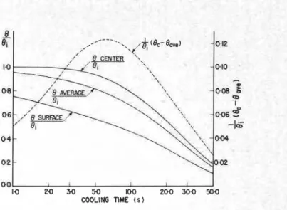
Fig. 5-Theoretical time-temperature curves for glass plate of thickness 0.59 cm cooled symmetrically with heat-transfer coefficient of 0.01 callcm2 s " C (418.7 Wm-'K-I)
zero for plate glass at temperatures higher than 620°C, which is known to be not valid. Sinha6 showed that the stress-optical coefficient of annealed plate glass was independent of temperature up to the upper part of the transformation range, around 600°C, and apparently decreases at temperatures higher than 600°C at a rate dependent on the wavelength of radiation in the spectral range, 400 to 850 nm. In the visible range, it was shown that the stress-optical coefficient at 650°C is only 20 percent lower than the corresponding room-temperature value. Moreover, Acloque relied on Bartenev's3 tempering theory for predicting the transient stress or strain condition in glass undergoing heat treatment. Bartenev developed his theory primarily to give a measure of final residual stress in an infinite plate. Gardon" showed that Bartenev's method gives quantitative agreement with the final stresses for a moderate cooling rate but does not agree with high rates of quenching. Bartenev introduced the concept of a moving solidification boundary, above which stresses relax immediately and below which no relaxation of stress occurs. This is believed to be invalid, and Sinha6 showed that, even at 620°C, the stress relaxation time of plate glass is close to 10 s.
The method to be presented here utilizes the transient thermal stress-induced birefringence in glass plates at temperatures much below the transformation range,* where the stress relaxation time is of the order of years, and the material can safely be considered as perfectly elastic.
Consider a rectangular plate (Fig. 2) 2s thick, initially heated to a uniform excess temperature, 0,, over the ambient temperature and subjected to a symmetrical forced cooling with a heat-transfer rate of h3 along x3 at the surfaces x, =
+
s (please note : & has been replaced by s for convenience).The temperature 0 , at any time 7 , of a plane at a
distance x3 from the mid-plane of the plate is givenI2.l3 by,
m
0 2 sin 4, 2 Br
- = C
e - @ n T c ~ s ( ~ ) 4 X3 (18)0,
.
=,
4,+
sin 4, cos 4, swhere 4.s are the roots of a transcendental equation * The term 'transformation range' is commonly used in glass literature to indicate the range of temperature where the tensile viscosity is in the neighborhood of 1 0 ' ~ poise.
The average temperature at the considered time is given by
From eqs (18) and (20)
For the condition where 0, is much below the transformation range, the thermoelastic stress of
d
at X3 and time 7 isS
where E , a and v are, respectively, Young's modulus,
coefficient of linear expansion and Poisson's ratio.
The corresponding birefringence along
x2
at PI = 0 in arectangular specimen, PI
> >
P3 (for which u: and a: areshown to be negligible) is given, substituting from eq
(22) in general eq (13), by
000
E
I I I 10 10 2 0 30 4 0 5 0 COOLING TIME S
Fig. 6-Variation of the difference of temperature
0
between the mid-plane and the average,
'
-with time for various heat-transfer rates, showing the maximum differences
where
200 4 0 0 600 BOO 1000
-
Fig. 7-The maximum difference of the mid- plane and the average temperature as a function of the coefficient of heat-transfer rate
Thus, the relative retardation is a direct function of
(13/8, - 8. ../8,) for a given specimen and for a given
initial temperature. From eqs (21) and (23),
EaO, 2 sin 4.
R2 = 2t'zKC,-
{
z
1 - v
.=,
(+,,+ sin+, cos4,) Theoretical temperature-time curves for a glass plate 0.59-cm thickness cooled symmetrically with a heat-transfercoefficient of 0.01 cal/cm2 s OC(418.7 Wm-W1) are
shown in Fig. 5. The numerical evaluations are based on material properties given in Table 2.
Figure 6 shows the variation of (8,/Oi - Om.. /Oi) with time for a few different heat-transfer rates. The subscript c is used to indicate the center or middle-plane value. The
maximum value of (8./Oi - O.../O,) is a function of heat-
transfer rate and its variation with this rate is given in Fig.
7. The method of determining the heat-transfer rate is
thus reduced to the measure of the maximum relative retardation in the mid-plane of a glass plate of given thickness, undergoing heat treatment, provided the initial temperature of the glass is known.
In this treatment, transfer of heat due to radiation and its effect on thermal conductivity are neglected. It has been observed by many researchers that the thermal conductivity of glass depends on the method of determining its value. This is due to the interplay of true thermal conductivity and the heat loss due to radiation and, hence, the term radiation conductivity was introduced
into the glass literature. GardonIs has shown that, as the external heat-transfer rate increases, the measured thermal conductivity approaches the true value of thermal con- ductivity. This is due to the greater relative decrease of radiation loss compared with the conduction loss. At high rates of cooling, as used in the present experiments, radiation loss amounts to only a small fraction of one percent and therefore may be neglected.
Experimental Determination of Heat-transfer Rate
A glass specimen 5.9 mm x 25 mm
x
150 mm, wassupported by a special tong designed for rigidity. The tong was equipped with an adjustable pressure mani- pulator for controlling the required minimum penetration of the tong in the glass at high temperature. The specimen and the optical system were arranged to remain stationary while the furnace and cooling unit, mounted together (Fig. 8) on a carriage, moved back and forth by means of a crank and pitman, activated electrically by a micro- switch at a predetermined time. The furnace was controlled to give uniform temperature distribution within the specimen, and was equipped with sliding doors that
opened and closed automatically as the carriage supporting
the furnace was moved to accommodate the specimen. A collimated and linearly polarized (45 deg to the vertical) light beam entered the furnace through a circular hole at the rear wall of the furnace, passed through the specimen and entered a divided optical imaging system, shown schematically in Fig. 8. One part of the light beam continued in its original direction and formed an image of the specimen on a white screen with a centrally located hole. An analyzer with a matching hole produced the isochromatic pattern on the screen for direct viewing and assisted also with sample alignment. The undisturbed portion of the beam, going through the holes in the analyzer and the screen, entered an automatic analyzer16 which recorded the mid-plane birefringence as a function
of time on an x-y recorder. Another part of the original
light beam produced an image of the specimen on the rear surface of a pair of quartz wedges, forming a system of interference fringes, which were photographed (Fig. 9) by a motor-driven 35-mm Nikon F camera. Both the camera and the automatic analyzer were triggered by a microswitch operated by the cooling unit.
AUTOMATIC SP(ARM0NT RECORDER
I IIMPCIE-FORMING
Fig. 8-Schematic diagram of the experi- mental system
Two types of cooling units were used : a forced-
convection system and a contact-cooling system. The former consisted of a pair of oscillating slotted frames mounted on the furnace carriage. The air was forced through the slots to the specimen, and the preselected air pressure was regulated by a gage and a manometer. The contact-cooling unit consisted of a pair of specially designed metallic blocks, covered with fiberglass cloth and associated air manifolds at the edges which was used to control the edge cooling. The blocks were maintained at a given temperature by a water jacket and controlled by a constant-temperature bath. The blocks were actuated by an air cylinder to a predetermined pressure at a pre- determined time. The cooling units were interchangeable and both were activated by a microswitch operated by the movement of the furnace through a system of timers.
An experimental observation (8; = 160°C) of the
change in relative retardation at the mid-plane with cooling time, for the forced-air cooling, is shown in Fig. 10. The relative retardation reaches its maximum value of 285 nm/cm about 6 s after the start of cooling. This maximum value of R2 gives, using eq (24) and Table 2, the corres-
ponding maximum value of (8, - 8...)/8, as 0.1027 which
gives the corresponding heat transfer coefficient of 0.0075 cal/cm2 s
"
C(314 Wm-2K-') from Fig. 7.To check the validity, theoretically predicted values of mid-plane retardation for different times corresponding to the heat transfer rate of 0.0075 cal/cm2 s "C(314 Wm-'K-') were calculated using eq (25). Experimental and theoretical results are compared in Fig. 10. Considering the errors involved, agreement is fairly good. It is concluded that the method of determining the heat-transfer rate from the transient birefringence in a glass, induced thermally by forced convection, gives fairly accurate and satisfactory results. This method has been used extensively to calibrate the cooling rates for various air pressures and the results have been compared in each case with the corresponding theoretical predictions. Experiments were also carded out by varying the initial temperature. However, the upper limit of usable temperature is limited by the strength of glass, and also by the condition that glass should be in the elastic region.
Agreement between experimental observations and calculated results, for contact cooling, was unsatisfactory. An example is shown in Fig. 11 for two different initial temperatures. Both the experimental observations give the same heat-transfer rate, but both differ from the theoretical
MOVABLE BEAM-SPLITTING FURNKE ( MIRROR I-,'---'
,---
. .. BABlNET COMPENSATOR POLAROID UGHT I SMRIEE COLLlMATlW LENS "AROID?h
CAMERAcurves in a similar manner. The disagreement is primarily due to the variation in the ambient temperature, in this case, the temperature of the cooling blocks. Thermocouples embedded in the cooling block indicated a gradual rise of the ambient temperature, which resulted in the gradual decrease in the heat-transfer rate with time. Heat-transfer rate, determined from the maximum relative retardation, gives a value lower than the actual rate during the first
5 s and a higher value after this time. Experience shows that thermal tempering is complete within the first 10 s at this rate of heat transfer. The experimentally determined value of the heat-transfer rate, therefore, may be con- sidered as an average rate within the tempering time.
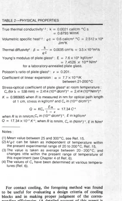
PHYSICAL IES
True thermal conductiv~ry,,- : K = U.UUL I callcrri - L s
= 0.8793 WlmK
Volumetric specific : ec = 0.6 callcm3 "C = 2.
Jlm3K k
Thermal diffusivity2 :
0
= - = 0.0035 cm21s = 3.5 x 'e c
Young's modulus of plate glass3 : E = 7.6 x
lo5
kgflc= 7.4526 X 10'' . .
for a laboratory-annealed plate glass.
Poisson's ratio of plate glass3 : u = 0.201.
Coefficient of linear expansion : a = 7.7 x 10-61K
between 21 -200 O C
Stress-optical coefficient of plate glass4 at room temperature :
C, (for A = 538 mm) = 2.414 (loL3 dlcm2)-I = 2.414 (1012Nlm2)-1
K = 0.980665 when R is measured in nm for optical path length
of 1 cm, stress in kgflcm2 and C, in (1 013 dlcm2)-I
E a - 17.34 C-I Q = KC, - - 1 - u when R is in nm/cm,C. in (10'V1cm2)-', E in kgflcm2 Q = 17.34 X 1 0-7 K-', when R is nmlm, C, in (N/mZ)-l, E in Nlm2 Notes :
(1) Mean value between 25 and 300°C, see Ref. 15.
(2) k/ec can be taken as independent of temperature within the present experimental range of 20 to 20OoC, Ref. 15. (3) The value is taken as average between 20 - 200°C, and
cnanges llttle within the present range of temperature of this experiment (see Chapter 4 of Ref. 6).
(4) The values of C, have been determined at various tempera- tures (Ref. 6).
For contact cooling, the foregoing method was found to be useful for evaluating a design criteria of cooling blocks and in making proper judgment of the corres- ponding efficiencies. (A detailed account of this aspect is outside the scope of this paper.)
Fig. 9-Photographic illustration of the transient Discussion
birefringence 'n a glass plate (0.59 x 2.5 x 15.0
cm) subjected to contact cooling. 0, = 114"C, The 'Achilles heel' of toughened safety glass, as
ave h3 = 0.031 callcm2 s OC (1298 Wm-'K-I). mentioned by Garden," is its edges. Relatively light
Sequence of time, in seconds, is as marked. impact at the edges with a sharp object can cause failure.
White light has been used to illustrate the The weakness of the edges can be improved by introducing
movement of the neutral fringe a high level of compressive stresses in these regions during
A-538 nm
OPTICAL PATH
-
I crn-
EXPERI MENTAL--- THEORETICAL
Flg. 10-Thermal-stress-lnduced translent blrefrlngence In the mlddle plane of 0.59-cm
x 2.5-cm x 15.0-cm glass plate for forced-
alr coollng wlth a heat-transfer rate, h, =
0.0075 callcm2 s OC (314 Wm-'K-I), the lnltlal
temperatureo, = 160°C
"OOb
k
;O
I;
;5&
35;D
Fig. I 1 -Mid-plane through retardation of plate glass. 0.59 cm thick. during contact cooling by copper plattens covered with 0.01 78-cm fiberglass, contact pressure of 2.63 kgflcm2, initial temperature as shown. The theoretical curve for h = 0.01610 callcm2 s " C (674 Wm-2K-1)
-
EXPERIMENTAL---
THEORETICAL 0 I-
I I I I I 1 I I I 0 5 10 15 2 0 25 35 35 4 0 45 U (U LT C O O L I N G T I M E sthe tempering process. This model of stress distribution proposed in this presentation is also applicable to large plates of tempered glass. The edge compression can be controlled by a proper choice of the lateral heat-transfer condition during the tempering process resulting in a glass with stronger edges.
Summary
A simple model of the stress state has been presented for thermally tempered glass plate. The developed model is used for setting up the photoelastic equations that can be used to determine completely the three-dimensional stress field. Apart from explaining the discrepancies between the actual stress, determined by scattered-light technique, and the conventionally measured stress, the' new model explains the existence of a preferred fracture zone, and the futility of trying to establish strength-degree of temper relationship without clarifying the lateral stress distribution. The model could be used as a guide for controlling the stresses in thermally tempered glass plate by programming the various heat-transfer rates during the tempering cycle and, thereby, optimizing the process.
A method of determining the heat-transfer rate has been developed by using glass as an optical transducer. The technique is based on the analysis of transient bi- refringence in a rectangular glass specimen subjected to thermoelastic stresses produced by symmetrical and uniform rate of cooling. The method, therefore, does not affect the natural flow of heat induced by forced con- vection or contact cooling. Satisfactory results could be obtained for forced convective cooling. For contact cooling, the method provides a means of evaluating the cooling efficiency of the system.
Acknowledgments
This work is in partial fulfillment of the author's dissertation for a PhD degree at the University of Waterloo and was supported by a National Research Council of Canada grant. The author is indebted to J.T. Pindera for his support and encouragements, and gratefully acknowledges the assistance provided by colleagues of the
Division of Building Research, National Research Council of Canada, in the preparation of this paper.
This paper is a contribution from the Division of Building Research, National Research Council of Canada and is published with the approval of the Director of the Division.
References
I. Pindera, J.T. and Sinha, N.K., "Determination of Dominant Radiation in Polariscope by Means of Babinet Compensator," EXPERI- MENTA-L MECHANICS, 12 (I), 3842 (Jan. 1972).
2. Bateson, S., Hunt, J. W., Dalby, D.A. and Sinha, N.K., "Stress Measurements in Tempered Glass Plates by Scattered Light Method with a Laser Source," Bull. A. Ceram. Soc., 45 (2). 193-198 (1966).
3. Bartenev, G., Theory of the Mechanical Strengthening of Glass by Annealing, (Russian), Doklady Akad. Nauk, S.S.S.R., 60 (2). 257-260 (1948); "Investigation of Tempered Glass," (Russian), J. Tech. Phys.,
S.S.S.R., X I X (12) (1949).
4. Aggarwala, B.D. and Saibal, E., "Tempering Stresses in A n Infinite Glass Plate," Phys. Chem. Glasses, 2 (5). 137-140 (1961).
5. Lee, E.H., Rogers, T. G. and Woo, T. C., "Residual Stresses in a Glass Plate Cooled Symmetrically from Both Surfaces,'V. Am. Ceram. Soc., 48 (9). 480487 (1965).
6. Sinha, N.K., On the Studies of Rheo-Optical Response of Plate Glass in a Wide Temperature Range. PhD. Thesis, Univ. Waterloo, Waterloo, Ontario, Canada (1971).
7. Coker, E.G. and Filon, L.N.G., A Treatise on Photoelasticity, University Press, Cambridge, England (1931).
8. Kraus, C.A. and Darby, E.H., "A Study of the Conduction Process in Ordinary Soda-Lime Glass," J. Am. Chem. Soc., 44 (12). 2783-2797 (1922).
9. Ernsberger, F.M., Advances in Glass Technologv, Plenum Press, New York, 511-524 (1962).
10. Acloque, P., "Comparison Between Heat Transfer Conditions and Setting up of Strain in Glass during Heat Treatment," J. Am. Ceram. Soc., 44 (7), 364-373 (1961).
II. Gardon, R., The Tempering of Flat Glass by Forced Convection, VII In!. Cong. Glaw Brussels, Paper 79 (1965).
I2. Jakob, M., Heal Transfer, 1, John Wiley & Sons, Inc., New York (1949).
13. Carslaw, H.S. and Jaeger, J.C., Conduction of Heat in Solids, 2nd Edition, Oxford at the Clarendon Press (1959).
14. Johns, D.J., Thermal Stress Analysis, Pergamon Press, New York (1965).
IS. Gordon, R., "A Review of Radiant Heat Transfer in Glum," J. Am. Ceram. Soc., 44 (7). 305-312 (1961).
16. Hunt, J. W., Dalby, D.A. and Bateson, S., A Photoelastic Stress Analyser, Technique, Muirhead and Co., Ltd., Beckenham, England, 9 (1) (1965).
17. Garden, G.K., Characteristics of Window Glass, Not. Res. Council of Canada, Div. Bld. Res., Canadian Bld. Dig., (60) (1964).